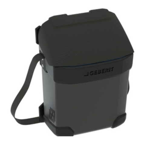
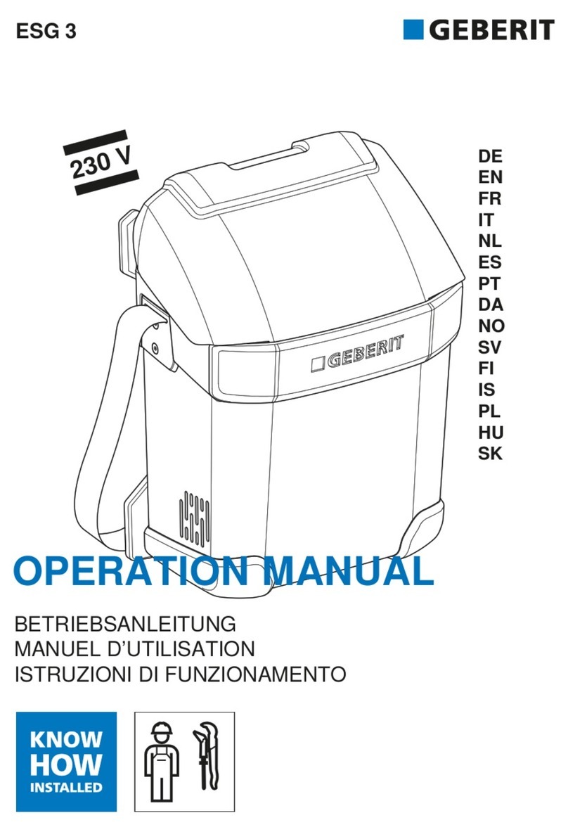
Geberit ESG 3 User manual

Instandhaltungsanleitung
Manuel d’entretien
Istruzioni per la manutenzione
ESG 3
Maintenance
Manual

EN
2D68129-001 © 04-2014
966.653.00.0 (00)
Information
Table of Contents
Information.......................................................................................................................................................................................... 2
Safety.................................................................................................................................................................................................... 3
Inspection............................................................................................................................................................................................ 4
Repair .................................................................................................................................................................................................... 5
Troubleshooting ............................................................................................................................................................................. 13
Product
This document contains all the information required for the professional maintenance of the following
products:
• 359.911.1P.1 Geberit electrofusion machine ESG 3 [115 V]
• 359.911.Px.x Geberit electrofusion machine ESG 3 [230 V]

EN
3
D68129-001 © 04-2014
966.653.00.0 (00)
Safety
Target group
Maintenance and repair on this product may only be performed by skilled persons in accordance with
EN IEC 62079:2001.
Intended use
The Geberit electrofusion machine ESG 3 may only be used for welding:
• Geberit electrofusion sleeve couplings ø 40–160 mm with Geberit PE and Geberit Silent-db20 pipes and
fittings
• Geberit electrofusion tapes for anchor points ø 50–315 mm with Geberit PE pipes and fittings
Any other use, or use extending beyond the intended application, is deemed to be improper. Geberit will not
accept any liability for any resulting damage.
Basic safety notes
Before executing any maintenance tasks, read the operating instructions and safety notes in document
966.475.00.0.

EN
4D68129-001 © 04-2014
966.653.00.0 (00)
Inspection
Visual check
Check the electrofusion machine for visual defects:
•cuts
•bumps
• excessive pollution
Completeness
Check the electrofusion machine for completeness:
• electrofusion sleeve coupling cable
• connecting cable for electrofusion coupling with integrated thermal fuse
• connecting cable set
•operationmanual
•snapcover
• carrying belt

EN
5
D68129-001 © 04-2014
966.653.00.0 (00)
Repair
Replacing the snap cover
1Remove the three screws on the inside of
the upper housing.
2Remove the damaged cover and mount the
new one.
3Fasten the new cover with the three screws.
Start with the middle screw to center the
cover.
Replacing the remote control
cable
1Disconnect the mains plug.
2Remove the electric pack entry cover.
3Disconnect the remote control cable
connectors and remove the remote control
cable.
4Mount the new remote control cable and
connect the remote control cable
connectors.
5Mount the electric pack entry cover.
Art. no. of new remote control cable:
• 242.947.00.1

EN
6D68129-001 © 04-2014
966.653.00.0 (00)
Replacing the mains cable
1Disconnect the mains plug.
2Remove the electric pack entry cover.
3Disconnect the mains cable connector and
remove the mains cable.
4Mount the new mains cable and connect the
mains cable connector.
5Mount the electric pack entry cover.
Disassembling the housing
1Remove the two lower screws on the upper
tripods and all four screws (M6 x 12 mm) on
the lower tripods.
2Untighten the eight screws on the inside of
the upper housing section (untight only - do
not remove).
Art. no. of new mains cable:
• 242.948.P4.1
• 242.948.P0.1
• 242.948.P6.1
• 242.948.P5.1
• 242.948.1P.1

EN
7
D68129-001 © 04-2014
966.653.00.0 (00)
3Hold down the lower housing section with
the carrying belt and separate the upper
section from the lower section.
4Remove the electric pack entry cover by
removing the four screws (M4 x 10 mm).
5Disconnect the mains cable connector.
6Disconnect the remote control cable
connectors.
7Lift the rubber seal below the electric pack
entry and pull out the electric pack from the
upper housing section.

EN
8D68129-001 © 04-2014
966.653.00.0 (00)
8Remove left and right protective bumpers to
the sides. Make sure the housing clips do
not fall off.
9Remove the seal from the electric pack
entry.
10 Disconnect the fan cable inside the electric
pack entry and remove the tapes from the
electric pack.
Replacing the electric pack seal
1Remove the housing clips (seven big and
two small clips) and carefully open the
electric pack.

EN
9
D68129-001 © 04-2014
966.653.00.0 (00)
2Remove the seal and replace it. Ensure that
the notch is at the top.
3Carefully assemble the housing. Make sure
that the seal fits tight on both sides of the
cooling element.
Add the housing clips to fix the housing.
4Connect the fan cable and secure the cable
with tape.
Replacing the fan
1Remove the seal on the right and dismount
the fan.
2Replace the fan.
3Hold the fan while mounting the seal right
and left.

EN
10 D68129-001 © 04-2014
966.653.00.0 (00)
Assembling the electric pack and
the housing
1Attach the upper part of the housing to
close the electric pack. Make sure the seal is
correctly positioned.
2Add the housing clips to fix the housing
(seven big and two small clips).
3Connect the fan cable connector inside the
electric pack. Make sure the cable passes
the provided recess in the electric pack
entry seal.
Fix the fan cable with tape to the electric
pack.
4Attach the right and the left protective
bumper to the electric pack. Make sure all
housing clips are positioned correctly.

EN
11
D68129-001 © 04-2014
966.653.00.0 (00)
5Pull the upper housing section over the
electric pack. Make sure the rubber seal fits
tight around the electric pack entry.
6Connect the mains cable connector inside
the electric pack entry.
7Snap in the remote control cable into the
recess of the upper housing section.
8Connect the remote control cable
connectors inside the electric pack entry.
9Mount the electric pack entry cover (four
screws M4 x 10 mm). Make sure the seal is in
the correctly positioned.
10 Insert the upper housing section with the
electric pack into the lower housing section.

EN
12 D68129-001 © 04-2014
966.653.00.0 (00)
11 Make sure the bumper of the upper housing
section slides over the lower housing
section.
Push down the upper housing until no gap is
visible between the upper and lower
housing parts.
12 Tighten all eight screws on the inside of the
upper housing section. Make sure the cover
is placed as deep as possible while tighten
the screws to allow best cover closing.
13 Fasten the lower tripods with the four
screws (M6 x 12mm).
Use the two remaining screws to fasten the
upper tripods.
14 Test the electrofusion machine using the
test procedures described later in this
document.
If an electric pack needs to be replaced,
change the electric pack entry cover using a
new replacement nameplate.
15 Complete all necessary accessories
including cables and operating manual.

EN
13
D68129-001 © 04-2014
966.653.00.0 (00)
Troubleshooting
Functional tests
Functional tests can be carried out as follows:
• simple tests: use commercially available electrofusion sleeve couplings d40–315
• detailed tests: follow the ESG 3 test setup below
ESG 3 test setup
Provide the following material for the test setup:
• power supply, 230 V, fused with min. 10 A
• electrofusion machine ESG 3
• connecting cable for electrofusion coupling
• connecting cable for electrofusion coupling with integrated thermal fuse
• multimeter with range 10 A DC and 10 A AC
• double sliding resistor Culatti 2 x 38 Ω, 2 x 1200 W, 5.5 A, can be obtained via Grossenbacher Systeme
AG (address see last page)
Figure 1: Test setup
This test setup can be used for all types of electrofusion machines ESG 3 (110 V and 230 V types).
Testing with electro sleeve coupling
Execute the following steps:
If a test fails, refer to the error list on page 14.
Step Resistance Current Action Result, test OK
17Ω5 A DC Press start/stop button LED on,
after 80 seconds: LED off, LED on
2 36 Ω5 A DC Press start/stop button LED on,
after 80 seconds: LED off, LED on
3 36 Ω5 A DC Press start/stop button and
disconnect mains cable for
3 seconds to simulate a
power failure
The welding cycle restarts
automatically. If the welding cycle does
not restart, check the date settings or
the battery contact
4 68 Ω5 A DC Press start/stop button LED on,
after 80 seconds: LED off, LED on
5 72–110 Ω0.02 A DC Press start/stop button LED on, LED flashing,
welding not possible
230 V
ESG 3
ESG 3
Remote
control Multi-
meter
E-coupling: DC
T-coupling: AC
Sliding
resistor
2 x 38 ohms
L
N
4 m
orange 4 m
blue
GND
5 V
Rx
Tx

EN
14 D68129-001 © 04-2014
966.653.00.0 (00)
Testing with thermo fusion coupling
Execute the following steps:
If a test fails, refer to the error list on page 14.
Testing the remote control unit
Execute the following steps:
If a test fails, refer to the error list on page 14.
Error list
Errors are displayed with the LEDs on the remote control unit. For a detailed error analysis use the service
software.
More than one error can be active at the same time. The errors are displayed according to their priority
(important errors first).
Step Resistance Current Action Result, test OK
1 46 Ωapprox.
5AAC
Press start/stop button and press start/stop button
again after 1–2 minutes to interrupt the welding
process
Welding
process stops
2 31 Ωapprox.
7AAC
Press start/stop button and press start/stop button
again after 20 seconds to interrupt the welding
process.
After more than 20 seconds the resistor may overheat
Welding
process stops
3 22 Ωapprox.
10.5 A AC
Press start/stop button and press start/stop button
again after 10 seconds to interrupt the welding
process.
After more than 10 seconds the resistor may overheat
Welding
process stops
Step Action Result, test OK
1 Connect the remote control unit to a 5 V power supply:
GND to pin 4 (white), +5 V to pin 3 (violet) of white 4-pole
connector
2 Switch on the 5 V power supply All LEDs on,
after 3 seconds: all LEDs flashing
Bit Error description LED
no.
1 Relay test: DC not loaded flashing on on on on
2 Relay test: DC relay error flashing on on on on
3 Relay test: discharge error flashing on on on on
4 Relay test: DO Drive_ESLEEEVE error flashing on on on on
5 Relay test: PWM_OFF output error flashing on on on on
6 Relay test: TSLEEVE relay error flashing on on on on
7 Relay test: AC relay error flashing on on on on
8 Coupling type has changed after the relay test flashing – – – –
10 E-coupling: input voltage out of tolerance on – on – –
11 E-coupling: no power or out of tolerance on – – – on
15 T-coupling: input voltage out of tolerance on – on – –
16 T-coupling: welding current not interrupted on – – – on
17 T-coupling: welding current stopped too early on – – – on
20 Disturbed communication to remote control flashing – – –
21 Earth leakage circuit breaker has triggered on on – – on
22 Self-test error flashing – – – –

EN
15
D68129-001 © 04-2014
966.653.00.0 (00)
Functional check prior to delivery
After a successful repair, execute a functional test prior to the delivery. The functional test is described
earlier in this document.
23 External watchdog flashing – – – –
24 Heat sink temperature too high on on – – –
25 Ambient temperature too low on – – on –
26 Welding aborted by user flashing – – – –
27 Maximum number of weldings reached flashing – – – –
28 Ambient temperature too high on on – – –
30 General error flashing – – – –
Bit Error description LED
no.

EN
16 D68129-001 © 04-2014
966.653.00.0 (00)
Available spare parts
Spare parts have to be obtained from the respective Geberit sales company. The Geberit sales company
orders the spare parts at the supplying factory in Pfullendorf, Germany.
Pos. Art. no. Designation To be replaced by:
1 242.946.00.1 Connecting cable Plumber
2 242.945.00.1 Connecting cable for electrofusion coupling with
integrated thermal fuse
Plumber
3 242.966.00.1 Connecting cable for electrofusion coupling Plumber
4 242.947.00.1 Remote control with cable Electrically skilled person
5 242.948.P4.1 Mains cable 230 V, SEV T12 Electrically skilled person
5 242.948.P0.1 Mains cable 230 V, CEE 7/7 Electrically skilled person
5 242.948.P6.1 Mains cable 230 V, AS / NZS 3112 Electrically skilled person
5 242.948.P5.1 Mains cable 230 V, BS 1363 A Electrically skilled person
5 242.948.1P.1 Mains cable 115 V, CEE 17 Electrically skilled person
Mains cable and remote control with cable may only be replaced by an electrically skilled person!
5
4
3
2
1

EN
17
D68129-001 © 04-2014
966.653.00.0 (00)
Available service spare parts
Service spare parts can only be obtained by the service centre directly from the manufacturer.
Pos. Art. no. Designation To be replaced by:
1 359.087.00.1 Electric pack entry cover Service centre or manufacturer
1.1 359.088.00.1 Seal for electric pack entry cover Service centre or manufacturer
2 359.071.00.1 Upper housing section Service centre or manufacturer
3 359.072.00.1 Covering hood Service centre or manufacturer
4 359.076.00.1 Electric pack with fall impact cushioning Service centre or manufacturer
4.1 359.089.00.1 PCA Manufacturer only!
4.2 359.078.00.1 Electric housing with seal Service centre or manufacturer
4.2.1 359.079.00.1 Housing seal Service centre or manufacturer
4.3 359.077.00.1 Electric pack fall impact cushioning Service centre or manufacturer
5 359.086.00.1 Housing clip, small (2 pieces) Service centre or manufacturer
6 359.085.00.1 Housing clip, large (2 pieces) Service centre or manufacturer
7 359.090.00.1 Fan with seal Service centre or manufacturer
7.1 359.091.00.1 Fan seal (2 pieces) Service centre or manufacturer
8 359.074.00.1 Carrying belt fixture, left and right Service centre or manufacturer
9 359.069.00.1 Tripods, left and right Service centre or manufacturer
12
11
10
10
9
9
8
8
7.1
7.1
7
7
6
6
6
5
4.3
4.3
4.2.1
4.2 4.1
4
3
2
1.1
1
12
11
10
10
9
9
8
8
7.1
7.1
7
7
6
6
6
5
4.3
4.3
4.2.1
4.2 4.1
4
3
2
1.1
1

EN
18 D68129-001 © 04-2014
966.653.00.0 (00)
10 359.094.00.1 Lower housing section with carrying belt and
carrying belt fixture
Service centre or manufacturer
11 359.075.00.1 Remote control protective cover Manufacturer only!
12 359.073.00.1 Carrying belt Service centre or manufacturer
Service spare parts may only be replaced by qualified service centres or by the manufacturer
(Grossenbacher Systeme AG, Switzerland). PCA repairs may only be carried out by the manufacturer.
Pos. Art. no. Designation To be replaced by:

EN
19
D68129-001 © 04-2014
966.653.00.0 (00)
Operation with service software
Function overview
The service software can be used for the following tasks:
• read parameters form electrofusion machine ESG 3
• export parameters
• store service messages
• analyse errors
The service software communicates with the electrofusion machine ESG 3 via a virtual COM port. It works
with all possible COM port settings (baud rate, parity, stop bits, etc.).
During an active communication, no weldings are possible.
Reading general information
Open tab Aktuelle Werte / Kalibrationswerte to show general information.

EN
20 D68129-001 © 04-2014
966.653.00.0 (00)
Reading counter values and service messages
Open tab Zähler / Servicemeldungen to show counter values and service messages.
The field Zähler shows the welding history.
The field Servicemeldungen allows to enter an individual comment for each service action. This allows for
example to track the service history of the electric pack. The messages are stored in the RAM of the
electrofusion machine ESG 3. The length of a message is 32 characters.
To shorten the messages use the following service codes:
• C1: electrofusion sleeve coupling cable
• C2: connecting cable for electrofusion coupling with integrated thermal fuse
• C3: remote control cable
•C4:mainscable
• C5: electric pack
•C6:fan
•C7:housingcover
•C8:upperhousingsection
• C9: lower housing section
Other manuals for ESG 3
3
Table of contents
Other Geberit Welding System manuals

Geberit
Geberit ESG light User manual

Geberit
Geberit ESG 3 User manual

Geberit
Geberit ESG light User manual

Geberit
Geberit KSS-160 User manual

Geberit
Geberit ESG 3 User manual

Geberit
Geberit ESG 3 User manual

Geberit
Geberit KSS-160 User manual

Geberit
Geberit ESG 40/200 User manual

Geberit
Geberit UNIVERSAL User manual
Geberit
Geberit MEDIA 160 User manual
Popular Welding System manuals by other brands

Magmaweld
Magmaweld COMPACT Series user manual

Wire wizard
Wire wizard Powerball Operation manuals

Lincoln Electric
Lincoln Electric POWERARC 5500 SVM197-A Service manual

Kemppi
Kemppi MasterTig 235ACDC GM operating manual

Magmaweld
Magmaweld RS 350 M - MW user manual

Miller Electric
Miller Electric Coolmate Coolmate 4 Brochure & specs