Gecko MSPA-1-AS User manual

MSPA-1-AS
•Service Manual •
Visual step-by-step guide to easily
identify & correct technical problems!
GECKO

Contents
Preliminary
Required Material 3
Error Messages
"FLO" 11
"FLC" 15
"Prr" 17
"Prh" 19
"HL" 21
"FrE" 25
Miscellaneous
Parts List 59
Wiring Diagram 61
Professional Repair Kit 62
How to Replace the Board 51
Replace the Heater 55
Adjust the Pressure Switch 57
Troubleshooting
Nothing Works! 27
Spa Is Not Heating! 31
Pump 1 Does Not Work! 35
Pump 2 Does Not Work! 38
Blower Does Not Work! 41
Spa Light Does Not Work! 45
Ozonator Does Not Work! 47
Keys Do Not Work! 49
Programming
Jumper Setup 9
Power & Ground Check
GFCI 5
Electrical Wiring 6
GFCI Trips! 7

Service manual2
Important Safety Information
WARNING: Risk of electrical shock! All procedures described in this service manual
must only be performed by qualified personnel, in accordance with the
standards applicable in the country of installation and, whenever
possible, with the equipment powered off. When connecting the
equipment, always refer to the wiring diagram affixed to the inside of
your spa pack’s power box cover! This diagram always prevails over
the wiring diagram at the end of this manual.
All information given subject to technical modifications without notice.
In order to be as helpful as possible, most sections of this manual were written in two
distinct formats: problem-solving solutions are described using both troubleshooting
flow charts and step-by-step procedures.
They should be used in conjunction, flow charts giving a global overview of specific
problems while step-by-step procedures are more detailed.
Although this manual has been prepared with great care, some information may seem
erroneous or unclear to you. In this case, please do not hesitate to contact us with
your remarks or questions.

3MSPA-1-AS
Tools & Test Equipment:
Pack Parts:
Pliers
Phillips & flat screwdrivers
11/32" (M8) nut driver
1/4" (M6) open-end wrench
3/8" (M10) open-end wrench
Jumper cable
Multimeter
GFCI tester & digital thermometer (optional)
Temperature probe
High-limit sensor
MSPA-1-AS system board
(or complete spa pack)
Transformer
Pressure switch
Fuses
Top side control
The following tools, test equipment and components are necessary to
perform service calls on an MSPA-1-AS Power Spa Pack.
Notes: The equipment delivered may slightly differ from the illustrations shown in this manual.
Gecko Electronics Inc. sells Professional Repair Kits that include everything needed for
MSPA-1-AS Power Spa Pack servicing. For more information, go to the last page of this
manual.
PRELIMINARYRequired Material

Service manual4
Notes:

5MSPA-1-AS
If the GFCI trips, follow the troubleshooting flow chart below to identify the
source of the problem.
Is the
GFCI
properly
connected?
If the
GFCI is
still tripping,
disconnect
the power input
wires.
Is the
GFCI still
tripping?
Replace
the GFCI.
Replace
the board.
The cable
is defective.
Call an
electrician!
Replace
the
transformer.
Reconnect
one component
at a time
until the
GFCI starts
tripping.
Replace
the defective
component.
Verify the
GFCI wiring
diagram &
reconnect it.
yes
yes no
no
yes no
Disconnect all
outputs,
including the
two wires of the
heater & the
light cord.
Is the GFCI still
tripping?
POWER & GROUND CHECKGFCI Flow Chart

Service manual6
Note: For systems manufactured before 1999, if P43 & P44 are
missing, use a #6 gage (4 mm dia.) cable and install it
between Line 1 and Line 2.
1 x 230 VAC (32 A) input supply wiring
Proper wiring of the electrical service box, GFCI and spa pack terminal
block is essential.
•Make a visual inspection for signs of miswiring. Refer to the supplied wiring
diagram. Call an electrician if necessary.
POWER & GROUND CHECK Electrical Wiring
INPUT
CABLE
LINE
GROUND
LINE 1
NEUTRAL
LINE 2
NEUTRAL
USE OP-
TIONAL
JUMPER
Jumper JMP1 set in "HC" mode!
Note: For systems manufactured before 1999, if P43 & P44 are
missing, use a #6 gage (4 mm dia.) cable and install it
between Line 1 and Line 2.
1 x 230 VAC (16 A) input supply wiring
Jumper JMP1 set in "LC" mode!
LINE
GROUND
LINE 1
NEUTRAL
LINE 2
NEUTRAL
USE OP-
TIONAL
JUMPER
INPUT
CABLE

7MSPA-1-AS
POWER & GROUND CHECKGFCI Trips!
1• Verify if the GFCI is properly
connected.
2• If it is not, verify the GFCI wiring
diagram and reconnect it.
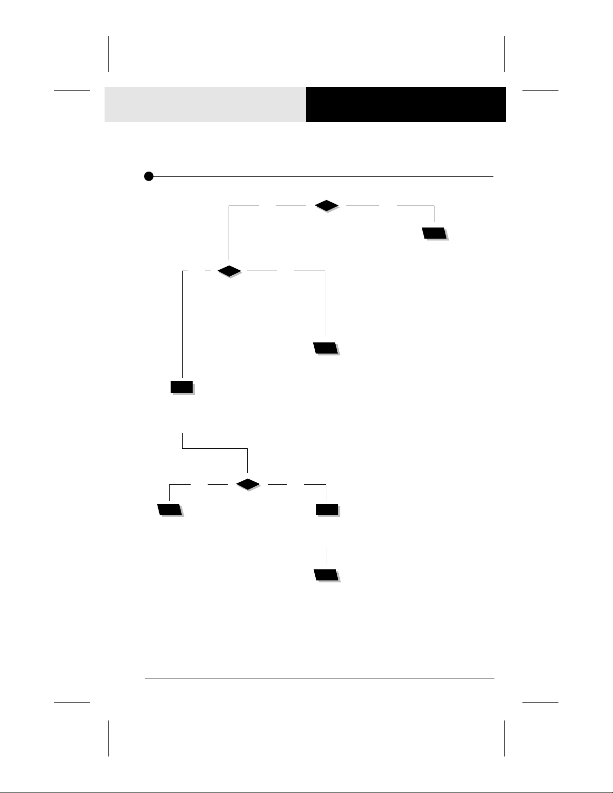
If the equipment is connected but nothing seems to work, the power supply
must be defective. Perform the following:
Note that in new installations, GFCI trippings due to miswiring are very common.
If the breaker is properly wired, GFCI trippings can occur when the total amount of current
drawn by the spa exceeds the rating of the breaker. Such an occurrence, however, is very
unlikely since each output of the spa pack is individually fused and fuses will blow before the
GFCI trips.
A current leak to the ground will also make the GFCI trip. If one of the components is faulty
and there is a leak of more than 5 mA, the GFCI will trip to prevent electrocution.
Several different models of GFCIs are available on the market. Note that our illustrations are
generic.
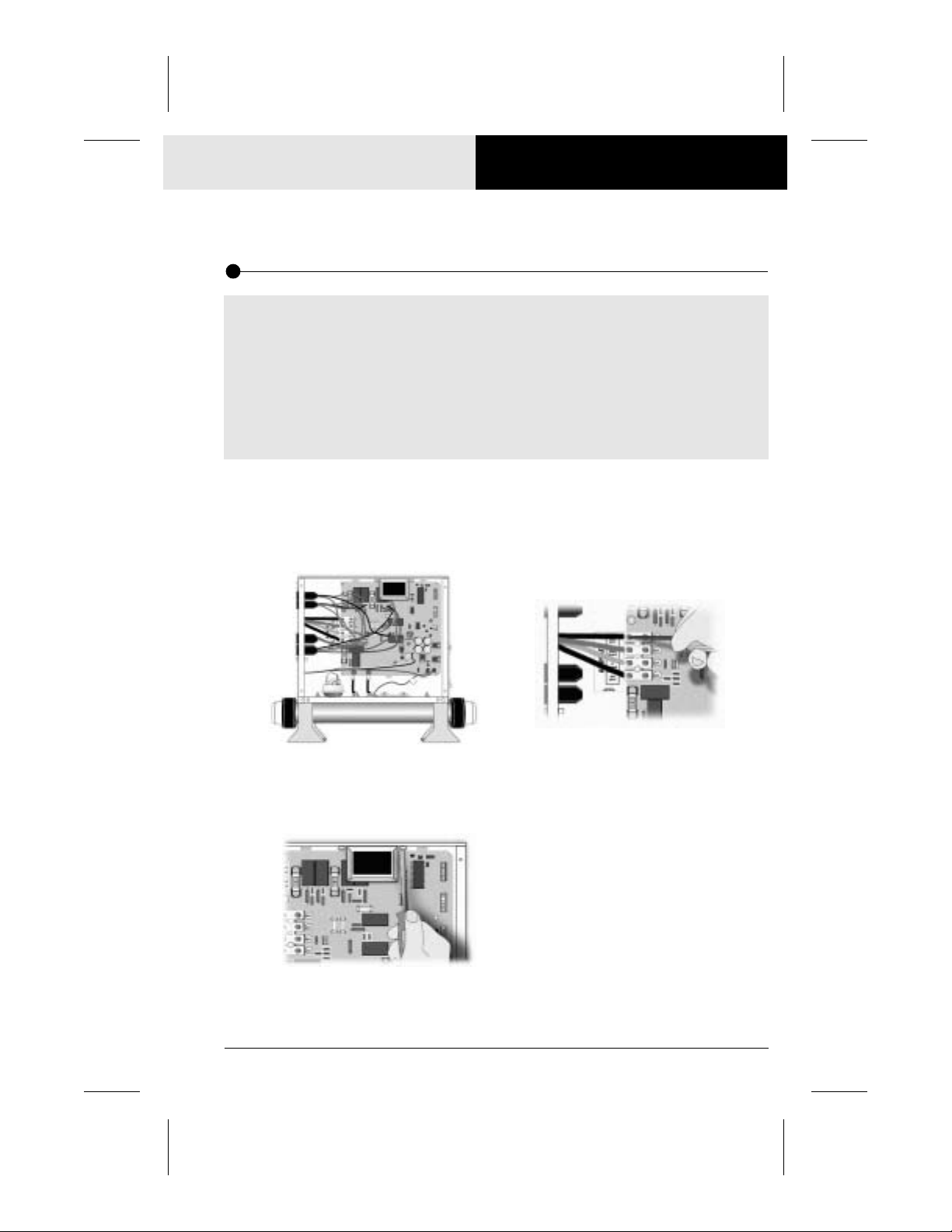
3• If the GFCI is properly connected but
still tripping, disconnect all outputs,
including the two wires of the heater &
the light cord.
4• If the GFCI still trips, replace the
transformer.
5• If the GFCI still trips even after the
transformer has been replaced:
a- Disconnect the power input wires.
If the GFCI still trips, the cable must
be defective.
Call an electrician!
b- If the GFCI stops tripping, replace it.
c- If the GFCI is still tripping, replace
the board referring to the "How to
Replace the Board" section of this
manual.
If it stops tripping, reconnect one com-
ponent at a time until the GFCI starts
tripping. Replace the defective com-
ponent.

Service manual8
Notes:

9MSPA-1-AS
PROGRAMMINGJumper Setup
2• To change a setting, simply pull the
jumper out using a pair of pliers and
replace it in the desired position.
It is possible to change some parameters of your MSPA-1-AS Spa Pack by
positioning specific jumpers located on the board.
To access the jumpers, first remove the plastic cover inside your MSPA-1-AS Spa Pack
power box referring to the "How to Replace the Board" section of this manual.
On your system, jumper functions may differ from the following. Check the supplied
wiring diagram affixed to the inside of the power box metal cover for your spa pack’s
specific functions.
Jumper location
Position 2Position 1
1• The jumpers are located on the upper
right section of the board.
Jumper JMP1: Current limiting option
Jumper JMP1 is used to limit the current drawn when the 2 pumps are used.
Position 1 (HC): The heater may not be turned on at the same time as pump 2.
Position 2 (LC): Pump 2 is disabled. Also, the heater may not be turned on if pump 1
is running at high speed or if the blower is on.
Jumper JMP2: Temperature display unit
Position 1: Temperature will be displayed in degrees Fahrenheit (ºF).
Position 2: Temperature will be displayed in degrees centigrade [Celsius] (ºC).
Jumper JMP3: Pump 1
Position 1: Two-speed pump.
Position 2: Single-speed pump.
Jumper JMP4: Pump 2
Position 1: Two-speed pump.
Position 2: Single-speed pump.

Service manual10
Notes:

11MSPA-1-AS
Replace the
pressure
switch cable.
ERROR MESSAGES"FLO" Flow Chart
The "FLO" message indicates a problem with the pressure switch. Pump is on
but no water pressure is detected. Follow the troubleshooting flow chart
below to identify the source of the problem.
Notes: For systems manufactured before 1998, you have to press a key after each
step to reset the system.
The heater barrel has to be installed on the pressure side of the pump and not
on the suction side.
Is the pump
running?
Refer to the "Pump Does
Not Work" section.
Remove
anything that may be
obstructing
the filter.
Clear any
air locks
& verify
the water
valves.
Verify if the
pressure switch
cable is properly
connected
to the pressure
switch and
to the board.
Verify if the spa pack contains
enough water to operate properly.
yes no
Is there anything limiting
the flow of water in the piping?
yes no
Is the installation
recent (less than
two years)?
Replace the
pressure switch.
Adjust the
pressure switch.
Make sure there is a flow of
water in the heater and short
the two terminals of the pressure
switch with a jumper cable.
Does the "FLO" message
disappear?
yes no
yes no
Replace
the board.

Service manual12
ERROR MESSAGES "FLO" Error Message
The "FLO" error message is displayed when a problem is detected with the
pressure switch. The system does not detect any pressure when the pump
is (whether manually or automatically) activated.
Note: The heater barrel has to be installed on the pressure side of the pump and
not on the suction side!
For systems manufactured before 1998, the "FLO" message remains displayed until any key is
pressed. Press a key after each step to reset the system.
The spa pack must contain enough water to operate properly. The "FLO" message can appear
if the spa filter is dirty or if something is limiting the flow of water in the piping.
For systems manufactured from 1998 onward, the heater is automatically turned off
whenever the "FLO" message appears. For systems manufactured before 1998, the pump and
the heater are turned off whenever the "FLO" message appears.
Power can remain on when the following steps are performed.
1• Verify if the pump (or circulation
pump) is running. If the pump is
not running properly, refer to the
respective section of this manual.
2• Make sure to clean the filter and to
look for air locks, closed valves or
anything that could limit the flow
of water in the piping.
3• Verify if the pressure switch cable is
properly connected to the pressure
switch and to the board.

13MSPA-1-AS
4• Make sure there is a flow of water in
the heater and short the two
terminals of the pressure switch with
a jumper cable.
5• If the "FLO" message disappears:
a- If the installation is older than
2 years, replace the pressure
switch and adjust it.
b- If the installation is recent, try to
adjust the pressure switch. If this is
not possible, replace the switch.
(Refer to the respective section of
this manual).
6• If the "FLO" message does not
disappear on the display, either the
pressure switch cable or the board
must be defective.
Remove the plastic cover and
replace the cable.
7• If the problem persists, replace the
board referring to the "How to
Replace the Board" section of this
manual.
ERROR MESSAGES"FLO" Error Message

Service manual14
Notes:

15MSPA-1-AS
The "FLC" message indicates a problem with the pressure switch. Pump is off
but water pressure is detected. Follow the troubleshooting flow chart below to
identify the source of the problem.
Disconnect the
pressure switch.
Does the "FLO" message
appear when the
pump is running?
Adjust the
pressure
switch.
Is the installation
recent (less than
2 years)? Replace the
pressure
switch cable.
If the "FLC" message
is still displayed
when you start or stop
the pump, replace the
pressure switch.
Replace the
pressure switch.
Replace the
board.
yes no
yes no
ERROR MESSAGES"FLC" Flow Chart
Note: For systems manufactured before 1998, you have to press a key after each
step to reset the system.

Service manual16
ERROR MESSAGES "FLC" Error Message
The "FLC" error message is displayed when a problem is detected with the
pressure switch. The system detects pressure while the pump is not
running.
2• If the "FLO" message does not
appear, remove the plastic cover
and replace the pressure switch
cable.
3• If the problem persists, replace
the board referring to the "How
to Replace the Board" section of
this manual.
1• Disconnect the pressure switch.
If the "FLO" message appears when
the pump is started, adjust the
pressure switch in the case of a recent
installation.
If this is not possible, replace the
switch.
(Refer to the respective section of this
manual).
For systems manufactured before 1998, the "FLC" message remains displayed until any key is
pressed. Press a key after each step to reset the system.
Power can remain on when the following steps are performed.

17MSPA-1-AS
Notes: For systems manufactured from 1999 onward, the "Prr" message is ignored
for an hour to allow the water temperature to reach 36 ºF (2 ºC).
Press a key after each step to reset the system!
The "Prr" message indicates a problem with the temperature regulation
probe. Follow the troubleshooting flow chart below to identify the source of
the problem.
Replace the board.
The water temperature must be over
36 ºF (2 ºC) for the spa to operate!
Verify if the temperature probe
is properly connected.
Replace the probe with a
spare one and verify if
the problem is solved.
If it is, replace the
defective probe.
Unplug the probe connector and
try to clean the pins on the board
(a small coating of film may cause a
bad connection).
Reconnect the probe.
ERROR MESSAGES"Prr" Flow Chart

Service manual18
ERROR MESSAGES "Prr" Error Message
The "Prr" error message is displayed when a problem is detected with the
temperature regulation probe: the system is constantly verifying if the
sensed temperature remains within normal range.
1• Remove the plastic cover and verify if
the temperature probe (the probe
located in the spa) is properly
connected to the board.
4• If the problem persists, replace the
board referring to the "How to
Replace the Board" section of this
manual.
3• Reconnect the probe.
If the "Prr" message is still displayed,
replace the probe by a spare one
and place its head directly in the
spa water.
If the problem is solved, replace
the defective probe.
2• Unplug the probe connector and try
to clean the pins on the board using a
screwdriver (a small coating of film may
cause a bad connection).
Note: For systems manufactured from 1999 onward, the "Prr" message is ignored
for an hour to allow the water temperature to reach 36 ºF (2 ºC).
The water temperature must be over 36 ºF (2 ºC) for you to perform the following steps.
Press a key after each step to reset the system.
Power can remain on when the following steps are performed.

19MSPA-1-AS
Replace the board.
Verify if the high-limit sensor
(the sensor touching the heater barrel)
is properly connected.
Replace the sensor with a spare one
and verify if the problem is solved.
If it is, replace the defective sensor.
Unplug the sensor connector and
try to clean the pins on the board
using a screwdriver (a small coating
of film may cause a bad connection).
Reconnect the sensor.
The "Prh" message indicates a problem with the high-limit sensor. Follow the
troubleshooting flow chart below to identify the source of the problem.
ERROR MESSAGES"Prh" Flow Chart
Note: Press a key after each step to reset the system!
Table of contents
Other Gecko Spa Accessories manuals

Gecko
Gecko Y Series User manual

Gecko
Gecko in.mix 300 Series User manual

Gecko
Gecko Aeware 3 in.ye User manual

Gecko
Gecko S-CLASS 0202-205162 Technical manual

Gecko
Gecko in.touch 2 User manual

Gecko
Gecko in.k300 User manual

Gecko
Gecko in.k1000 User manual

Gecko
Gecko M-CLASS MC-MP-SBD User manual

Gecko
Gecko Aeware In.Xe User manual

Gecko
Gecko in.k330 User manual

Gecko
Gecko Aeware3 in.ye User manual

Gecko
Gecko DJS-1 User manual

Gecko
Gecko in.k506 User manual

Gecko
Gecko BAHAMA SPAS Reference guide

Gecko
Gecko Y Series User manual

Gecko
Gecko in.ye-5 Technical manual

Gecko
Gecko in.yj-3 Technical manual

Gecko
Gecko in.ye-V3 User manual

Gecko
Gecko Aeware3 in.touch User manual