manuals.online logo
Brands
  1. Home
  2. •
  3. Brands
  4. •
  5. gefran
  6. •
  7. Relay
  8. •
  9. gefran GTZ 25 Configuration guide

gefran GTZ 25 Configuration guide

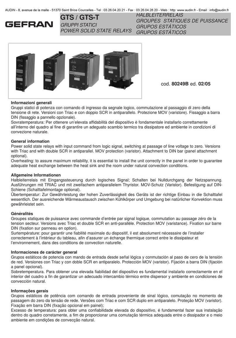
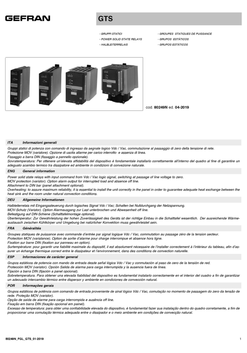
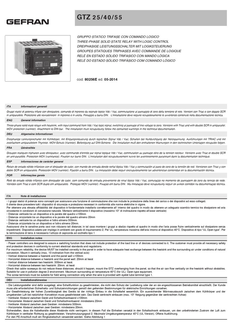
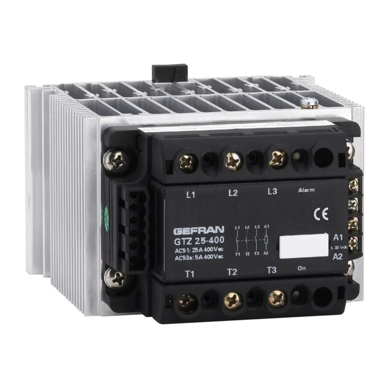
GTZ 25/40/55
GRUPPO STATICO TRIFASE CON COMANDO LOGICO
THREE-PHASE SOLID STATE RELAY WITH LOGIC CONTROL
DREIPHASIGE LEISTUNGSSCHALTER MIT LOGIKSTEUERUNG
GROUPES STATIQUES TRIPHASES AVEC COMMANDE DE LOGIQUE
RELÉ EN ESTADO SÓLIDO TRIFASICO CON MANDO LÓGICA
RELÉ DO ESTADO SÓLIDO TRIFÁSICO COM COMANDO LÓGICO
cod. 80256G ed. 04-2019
ITA Informazioni generali
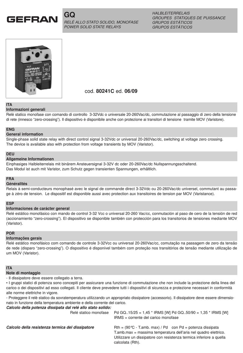
Gruppi statici di potenza trifase con dissipatore, comando di ingresso da segnale logico Vdc / Vac, commutazione al passaggio di zero della tensione di rete. Versioni con Triac e con doppio SCR
in antiparallelo. Protezione alle sovratensioni in ingresso e in uscita. Fissaggio a barra DIN. L’installazione deve seguire scrupolosamente le avvertenze contenute nella documentazione tecnica.
ENG General information
Three-phase solid state relays with heatsink, with input command from Vdc / Vac logic signal, switching at passage of line voltage to zero. Versions with Triac and with double SCR in antiparallel.
MOV protection (varistor). Attachment to DIN bar. The installation must scrupulously follow the contained warnings in the technical documentation.
DEU Allgemeine Informationen
Dreiphasige Leistungsschalter mit Kühlkörper, mit Eingangssteuerung durch logisches Signal Vdc / Vac; Schalten bei Nulldurchgang der Netzspannung. Ausführungen mit TRIAC und mit
zweifachem antiparallelem Thyristor. MOV-Schutz (Varistor). Befestigung auf DIN-Schiene. Die Installation muß den enthaltenen Warnungen in den technischen Unterlagen skrupulös folgen.
FRA Généralités
Groupes statiques triphases avec dissipateur, avec commande d’entrée par signal logique Vdc / Vac, commutation au passage zéro de la tension secteur. Versions avec Triac et double SCR
en anti-parallèle. Protection MOV (varistance). Fixation sur barre DIN. L’installation doit scrupuleusement suivre les avertissements paraissant dans la documentation technique.
ESP Informaciones de carácter general
Relais de estado sólido trifásicos con el disipador de calor, con mando de entrada desde señal lógica Vdc / Vac y conmutación al paso de cero de la tensión de red. Versiones con Triac y con
doble SCR en antiparalelo. Protección MOV (varistor). Fijación a barra DIN. La instalación debe seguir escrupulosamente las advertencias contenidas en la documentación técnica.
POR Informações gerais
Relé do estado sólido trifásico com dissipador de calor, com comando de entrada proveniente de sinal lógico Vdc / Vac, comutação no momento de passagem do zero da tensão de rede.
Versões com Triac e com SCR duplo em antiparalelo. Proteção MOV (varistor). Fixação em barra DIN. Ma instalação deve scrupulously seguir os avisos contidos na documentação técnica.
ITA Note di installazione
• I gruppi statici di potenza sono concepiti per assicurare una funzione di commutazione che non include la protezione della linea del carico o dei dispositivi ad esso collegati.
Il cliente deve prevedere tutti i dispositivi di sicurezza e protezione necessari in conformità alle norme elettriche in vigore.
Per ottenere una elevata affidabilità del dispositivo è fondamentale installarlo correttamente all’ interno del quadro in modo da ottenere un adeguato scambio termico tra dissipatore ed aria
circostante in condizioni di convezione naturale. Montare verticalmente il dispositivo (massimo 10° di inclinazione rispetto all’asse verticale)
• Distanza verticale tra un dispositivo e la parete del quadro >100mm
• Distanza orizzontale tra un dispositivo e la parete del quadro almeno 20mm
• Distanza verticale tra un dispositivo e l’altro almeno 300mm.
• Distanza orizzontale tra un dispositivo e l’altro almeno 20mm.
Assicurarsi che le canaline porta cavi non riducano tali distanze; in tal caso montare i gruppi a sbalzo rispetto al quadro in modo che l’aria possa fluire verticalmente sul dissipatore senza
impedimenti. Dispositivo adatto per impiego in ambienti con grado di inquinamento 2. Per UL, temperatura massima dell’aria intorno al dispositivo 40°C. Dispositivo di tipo “UL Open type”. Per
la terminazione di terra é necessario l’utilizzo di capicorda ad occhiello tipo 1
ENG Installation notes
• Power controllers are designed to assure a switching function that does not include protection of the load line or of devices connected to it. The customer must provide all necessary safety
and protection devices in conformity to current electrical standards and regulations.
For maximum reliability, the device MUST be installed correctly in the panel in order to have adequate heat exchange between the heatsink and the surrounding air under conditions of natural
convection. Mount it vertically (max. 10 inclination from the vertical axis)
• Vertical distance between a heatsink and the panel wall >100mm
• Horizontal distance between a heatsink and the panel wall: 20mm at least
• Vertical distance between two heatsink: 300mm at least.
• Horizontal distance between two heatsink: 20mm. at least
Check that cable raceways do not reduce these distances; should it happen, mount the GTZ overhanging from the panel, so that the air can flow vertically on the heatsink without obstables.
Suitable for use in pollution degree 2 environment. Maximum surrounding air temperature 40°C (for UL). Open type equipment.
The screw terminals must be suitable for field wiring connection only when the wire is provided with eyelet tube terminal type 1.
DEU Installationshinweise
• Die Leistungssteller sind dafür ausgelegt, eine Schaltfunktion zu gewährleisten, die nicht den Schutz der Lastleitung oder der an sie angeschlossenen Betriebsmittel einschließt. Der Kunde
muss alle erforderlichen Sicherheits- und Schutzeinrichtungen gemäß den geltenden Bestimmungen für elektrische Einrichtungen vorsehen.
Zur Gewährleistung der hohen Zuverlässigkeit des Geräts ist der richtige Einbau in die Schalttafel wesentlich. Ein ausreichender Wärmeaustausch zwischen dem Kühlkörper und der
umgebenden Luft bei natürlicher Konvektion muss gewährleistet sein. Das Gerät senkrecht einbauen (max. 10° Neigung gegenüber der senkrechten Achse)
• Vertikaler Abstand zwischen Gerät und Schaltschrankwand >100mm
• Horizontaler Abstand zwischen Gerät und Schaltschrankwand: mindestens 20mm
• Vertikaler Abstand zwischen zwei Geräten: mindestens 300mm.
• Horizontaler Abstand zwischen zwei Geräten: mindestens 20mm.
Sicherstellen, dass die Kabelkanäle diese Abstände nicht verringern; in diesem Fall die Einheiten versetzt in den Schaltschrank einbauen, um den unbehinderten Zustrom der Luft zum
Kühlkörper in vertikaler Richtung zu gewährleisten. Verschmutzungsgrad 2. Maximale Umgebungstemperatur 40°C (UL Version). Offene Ausführung.
Für den PE-Anschluß muß ein Ringkabelschuh verwendet werden. Siehe Abbildung 1
FRA Prescriptions de montage
• Les gradateurs de puissance sont conçus pour assurer une fonction commutation qui n’inclut pas la protection de la ligne de charge ou des dispositifs raccordés à celle-ci.
Le client devra prévoir tous les dispositifs de sécurité et de protection nécessaires, conformément aux normes électriques en vigueur.
Pour obtenir une plus grande fiabilité du dispositif, il est nécessaire de l’installer correctement à l’intérieur du tableau, de manière à assurer un échange thermique adéquat entre le dissipateur
et l’air ambiant dans des conditions de convection naturelle. Le dispositif doit être installé en position verticale (inclinaison maximale de 10° par rapport à son axe vertical)
• Distance verticale entre un dispositif et la paroi du tableau >100mm
• Distance horizontale entre un dispositif et la paroi du tableau: au moins 20mm
• Distance verticale entre un dispositif et l’autre : au moins 300mm.
• Distance horizontale entre un dispositif et l’autre : au moins 20mm.
S’assurer que les goulottes des câbles ne réduisent pas ces distances; dans ce cas, installer les groupes en porte-à-faux par rapport au tableau, de manière à ce que l’air puisse s’écouler
verticalement sur le dissipateur sans entraves. Dispositif adapté pour fonctionner en milieu industriel pollué de degré 2. Pour l’UL la température max de l’air autour du dispositif est de 40°C.
Dispositif du type “UL open”. Les vis du bornier doivent être du même diamètre que celui du trou de l’oeillet pour le type 1
ESP Notas de instalación
• Los grupos estáticos de potencia están previstos para garantizar una función de conmutación que no incluye la protección de la línea de carga ni de los dispositivos a él conectados. El
cliente debe instalar todos los dispositivos de seguridad y protección necesarios, en conformidad con lo establecido por las normas vigentes sobre equipos eléctricos. Para asegurarse de que
el dispositivo sea altamente fiable es fundamental instalarlo correctamente en el interior del cuadro, a fin de obtener un adecuado intercambio térmico entre disipador y aire circundante en
situaciones de convección natural. Montar verticalmente el dispositivo (máximo 10° de inclinación respecto del eje vertical).
• Distancia vertical entre un dispositivo y la pared del cuadro >100 mm.
• Distancia horizontal entre un dispositivo y la pared del cuadro de al menos 20 mm.
• Distancia vertical entre uno y otro dispositivo de al menos 300 mm.
• Distancia horizontal entre uno y otro dispositivo de al menos 20 mm.
Verificar que los canales portacables no reduzcan las distancias indicadas; en tal caso, los grupos deberán montarse en voladizo respecto del cuadro a fin de que el aire pueda fluir verticalmente
y sin obstáculos sobre el disipador. Dispositivo adecuado para uso en ambientes con grado de contaminación 2. Para UL, temperatura máxima del aire en torno al dispositivo 40 °C. Dispositivo
de tipo “UL Open type”. Los terminales del srew deben ser convenientes para la conexión del hilo inductor solamente cuando el alambre se proporciona tipo 1 del terminal del tubo del ojal.
POR Notas de instalação
• Os grupos estáticos de potência foram concebidos para garantir uma função de comutação que não inclui proteção da linha de carga ou dos dispositivos ligados à carga.
O cliente tem de providenciar por si a montagem de todos os dispositivos de segurança e proteção necessários, de acordo com as normas elétricas em vigor.
Para obter uma confiabilidade elevada do dispositivo, é fundamental fazer sua instalação dentro do quadro corretamente, a fim de proporcionar uma permutação térmica adequada entre o
dissipador e o meio ambiente, em condições de convecção natural. Monte o dispositivo verticalmente (com um máximo de 10° de inclinação em relação ao eixo vertical)
• Distância vertical entre qualquer dispositivo e a parede do quadro >100mm
• A distância horizontal entre qualquer dispositivo e a parede do quadro deve ser, pelo menos, de 20mm
• A distância vertical entre dois dispositivos consecutivos deve ser, pelo menos, de 300mm.
• A distância horizontal entre dois dispositivos consecutivos deve ser, pelo menos, de 20mm.
Assegure-se de que os conduites dos cabos não reduzam estas distâncias; em tal caso, monte os grupos em escada em relação ao quadro, de modo que o ar possa circular verticalmente no
dissipador sem encontrar obstáculos. Dispositivo indicado para uso em ambientes com grau de poluição 2. Para UL, temperatura máxima do ar à volta do dispositivo 40°C. Dispositivo tipo “UL
Open type”. Os terminais do srew devem ser apropriados para a conexão da fiação de campo somente quando o fio é fornecido com o tipo terminal 1 do tubo do ilhó.
Fig. 1 Models GTZ-25/xx-x-x (25A) Models GTZ-40/xx-x-x, GTZ-55/xx-x-x (40 and 55A)
NOTA_ITA: Per modelli GTZ-xx/xx-A-x (comando Vac) i terminali A1,A2,B1,B2 sono collegati mediante connettore estraibile
NOTA_ENG: For Models GTZ-xx/xx-A-x (Vac command) terminals A1,A2,B1,B2 are connected by plug connector
L1 L2 L3
AC51: 25A 400Vac
AC53a: 5A 50/60Hz
GTZ 25/400-0-1
On
L1 L2 L3 A1+
T1 T2 T3 A2-
Alarm B1
B2
A1
A2
5..32
Vdc
T1 T2 T3
L1 L2 L3
AC51: 40A 600Vac
AC53a: 8A 50/60Hz
GTZ 40/600-0-1
On
L1 L2 L3 A1+
T1 T2 T3 A2-
Alarm B1
B2
A1
A2
5..32
Vdc
T1 T2 T3
VEN-90
fan:230Vac
127mm 127mm
8
30mm
100mm50mm Max
80mm 8
30mm
Profondità/ Depth:
- Model GTZ-xx/xx-D-x : 150 mm
- Model GTZ-xx/xx-A-x : 158 mm
Ingombri:
Dimensions:
Außenmaße:
Dimensions hors-tout:
Dimensiones:
Dimensões externas máx:
Vedi
See
Sehen Sie
Voyez
Vea
Veja
Fig. 1
Fig. 1
Fig. 1
Fig. 1
Fig. 1
Fig. 1
Connessione:
Connection:
Anschluß
Raccordement:
Conexión:
Conexão:
Vedi
See
Sehen Sie
Voyez
Vea
Veja
Fig. 2
Fig. 2
Fig. 2
Fig. 2
Fig. 2
Fig. 2
Coppie di serraggio viti:
Screw tightening torque:
Anziehdrehmoment für mdie Schrauben
Couples de serrage des vis:
Pares de apriete tornillos:
Binários de aperto dos parafusos:
M3: 0,4-0,6Nm
M5: 1,5-2 Nm
terminals A1, A2, B1, B2
terminals L1, L2, L3, T1, T2, T3
Fig. 2
ESEMPIO DI COLLEGAMENTO/CONNECTION EXAMPLES - GTZ con comando DC/ with DC control (Models GTZ-xx/xx-D-x)
Collegamento carico trifase a triangolo o stella (con e senza neutro)
Three-phase Triangle or Star connection (with and without neutral)
* Solo nella versione con opzione uscita allarme sovratemperatura
* Only in the version with option overtemperature alarm output
ESEMPIO DI COLLEGAMENTO/CONNECTION EXAMPLES - GTZ con comando AC/ with AC control (Models GTZ-xx/xx-A-x)
(*) Solo nella versione con opzione uscita allarme
* Only in the version with option alarm output
R
R
R
RR
RRR
R
< 30V
V
I < 150 mA
F1 F2 F3
GTZ 25/60-D-1
50/6 0 Hz
600Vac
2/T1
AC51:25A
4/T2
1/L1 3/L2
6/T3
ON
A2
A1
B2
Alarm
5/L3
B1
246A2-
135A1+
5-32Vdc
AC53a: 5A
5-32 Vdc
+
-
Phase L1
Phase L2
Phase L3
Neutral
Ground
Load
Controller
Digital
output (*)
20........260 Vac/Vdc
< 30V
V
I < 150 mA
F1 F2 F3
(*)
ON/O FF
Switch
A2
A1
B2
B1
2 4 6 A2
1 3 5A1
20-260
nc
nc
On
4/T2
5/L3
1/L1 3/L2 Alarm
2/T1 6/T3
Out
Al
50/6 0 Hz
600Vac
GTZ 25/60-A-2
AC51: 25A
AC53a: 5A
Vac/Vdc
3 A
Phase L1
Phase L2
Phase L3
Neutral
Ground
80256G_FGL_GTZ_04-2019
GEFRAN spa
via Sebina, 74 - 25050 Provaglio d’Iseo (BS)
Tel. +39 030 9888.1 - fax +39 030 9839063 Internet: http://www.gefran.com
AVVERTENZE
Il dissipatore durante il fun-
zionamento continuato può
raggiungere tempe-rature
molto elevate ed inoltre man-
tiene una temperatura eleva-
ta anche successivamente lo
spegnimento a causa della
sua elevata inerzia termica.
WARNINGS
During continuous operation,
the heat sink can reach very
high temperatures, and keeps
a high temperature even after
the unit is turned off due to its
high thermic inertia.
SICHERHEITSHINWEISE
Der Kühlkörper kann während
des Dauerbetriebs sehr hohe
Temperaturen erreichen und
außerdem aufgrund seiner
großen Wärmeträgheit auch
nach der Abschaltung noch
sehr heiß sein.
AVERTISSEMENTS
Pendant son fonctionnement
continu, le dissipateur peut
atteindre des températures
très élevées, lesquelles peu-
vent persister même après la
mise hors tension du disposi-
tif, par effet de son importante
inertie thermique.
ADVERTENCIAS
Durante el funcionamien-
to continuado el dispersor
puede alcanzar temperaturas
muy elevadas y mantener
también una temperatura
elevada una vez apagado
debido a su elevada inercia
térmica.
ADVERTENCIAS
Em constante funcionamen-
to, o dissipador pode atingir
temperaturas muito elevadas
e, mesmo depois do desliga-
mento, mantém temperatura
elevada devido à sua alta
inércia térmica.
Non lavorare sulla parte di
potenza senza aver prima
sezionato la tensione di ali-
mentazione del quadro.
DO NOT work on the power
section without first cutting
out electrical power to the
panel.
Nicht am Leistungsteil
arbeiten, ohne vorher die
Versorgungsspannung des
Schaltschranks abgeschaltet
zu haben.
Ne pas intervenir sur la partie
de puissance sans avoir préa-
lablement coupé la tension
d’alimentation du tableau.
No trabajar en la parte de
potencia sin seccionar previa-
mente la tensión de alimenta-
ción del cuadro.
Não trabalhe na parte de
potência se não tiver inter-
rompido previamente a
tensão de alimentação do
quadro.
Attenersi alle indicazioni pre-
senti sul manuale tecnico.
Follow the instructions in the
technical manual.
Die Anweisungen im techni-
schen Handbuch beachten.
Respecter les prescriptions
du manuel technique.
Atenerse a las indicaciones
del manual técnico.
Siga as indicações dadas no
manual técnico.
I dispositivi sono prodotti in accordo con le Direttive Comunitarie: 2011/65/EU (RoHS), 2014/30/EU (EMC), 2014/35/EU (LVD)
e in accordo con le seguenti norme: EN 50581:2012 e EN 60947-4-3:2014
The device are manufactured according with the Community Directives: 2011/65/EU (RoHS), 2014/30/EU (EMC), 2014/35/EU (LVD)
with reference to standard: EN 50581:2012 and EN 60947-4-3:2014
Die Geräte werden in Übereinstimmung mit den folgenden EU-Richtlinien hergestellt: 2011/65/EU (RoHS), 2014/30/EU (EMC), 2014/35/EU (LVD)
und entsprechen den folgenden Normen: EN 50581:2012 und EN 60947-4-3:2014
Les dispositifs sont produits conformément aux Directives Communautaires : 2011/65/EU (RoHS), 2014/30/EU (EMC), 2014/35/EU (LVD)
et conformément aux normes suivantes : EN 50581:2012 et EN 60947-4-3:2014
Los dispositivos se fabrican de acuerdo con las Directivas Comunitarias: 2011/65/EU (RoHS), 2014/30/EU (EMC), 2014/35/EU (LVD)
y de acuerdo con las siguientes normas: EN 50581:2012 y EN 60947-4-3:2014
Os dispositivos são produzidos de acordo com as Diretivas Comunitárias: 2011/65/EU (RoHS), 2014/30/EU (EMC), 2014/35/EU (LVD)
e de acordo com as seguintes normas: EN 50581:2012 e EN 60947-4-3:2014
SCCR RMS SYM
100KA / 600V
100KA when protected by proper fuse
®In Conformity with UL508 - File: E243386
Conformity TC RU C-IT.AЛ32.B.00422
FUSIBILI EXTRARAPIDI - EXTRARAPID FUSES
Modelli /
Model i2t
Tensione
nominale / Max
Voltage
Taglia
/ Size
Dimensione mm /
Dimension mm
Sigla di ordinazione
fusibile /
Fuse ordination code
Sigla di ordinazione
portafusibile / Fuse holder
ordination code
Note/
Notes
GTZ 10A 100 400 10A 10x38 FUS-10-L PF-10x38 estraibile /
extractable
GTZ 25A 450 400 25A 12x32 FUS-025 PF-10x38 estraibile /
extractable
645 480
GTZ 40A 1010 480 40A 14x51 FUS-040 PF-14x51 estraibile /
extractable
600
GTZ 55A 6600 480 63A 22x58 FUS-063 PF-22x58 estraibile /
extractable
600
SCCR COORDINATION FUSES
Model Short circuit current [Arms] Max fuse size [A] Bussmann Model Number Max Voltage [VAC]
GTZ 25 100.000 25 DFJ-25 600
GTZ 40 100.000 40 DFJ-40 600
GTZ 55 100.000 80 DFJ-80 600
I fusibili sopra indicati sono rappresentativi di tutti i fusibili Bussmann DFJ con rating di corrente inferiore
The fuses on the above table are representative of all the Bussmann DFJ fuses with lower current ratings
I dispositivi protetti con fusibili sopra riportati sono ancora funzionanti dopo il cortocircuito
The devices protected with the fuses reported above, still be functional after the short circuit
ITA Protezione al corto circuito
i prodotti elencati nella tabella “tabella fusibili SCCR” sono utilizzabili in circuiti in grado di fornire non più di 100.000 A rms simmetrici, massimo 600 Volt, quando protetti da fusibile appropriato.
Attenzione: l’apertura del fusibile può indicare che un corto circuito è stato interrotto. Per ridurre il rischio di incendi e shock elettrici, le parti in tensione e altri componenti del dispositivo devo-
no essere esaminati e se danneggiati, devono essere sostituiti. Se il dispositivo è completamente bruciato deve essere sostituito.
ENG Short circuit protection
The product variants listed in the table “SCCR Fuse protection table” are “Suitable For Use On A Circuit Capable Of Delivering Not More Than 100,000 A rms Symmetrical Amperes, 600 Volts
Maximum when Protected by fuses.
Attention: t he opening of the branch-circuit protective device may be an indication tha a fault has been interrupted. To reduce the risk of ree or electric shocks, current-carryng parts and
other components of the device should be examinated and replaced if damaged. If burnout of the device occurs, the complete device must be replaced or equivalent.
This manual suits for next models

2

Other gefran Relay manuals

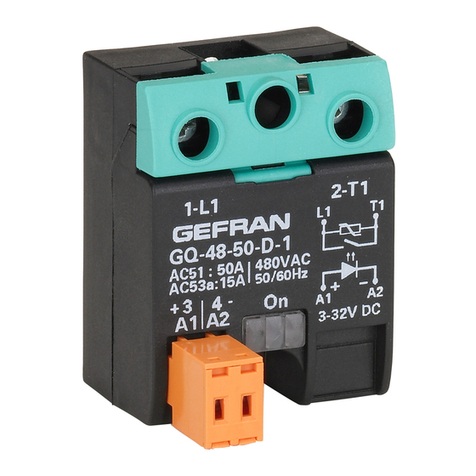
gefran GQ User manual

gefran

gefran GQ User manual

gefran GTS User manual

gefran

gefran GTS User manual

gefran GQ 15 A Series Instruction manual

gefran

gefran GQ 15 A Series Instruction manual

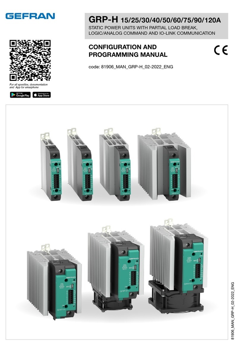
gefran GRP-H15A Owner's manual

gefran

gefran GRP-H15A Owner's manual

gefran GQ 15 A User manual

gefran

gefran GQ 15 A User manual

gefran GTS User manual

gefran

gefran GTS User manual

gefran GTZ 25 Series Instruction manual

gefran

gefran GTZ 25 Series Instruction manual

gefran GQ Series User manual

gefran

gefran GQ Series User manual

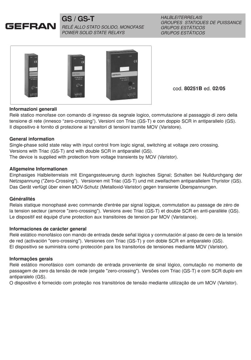
gefran GS User manual

gefran

gefran GS User manual

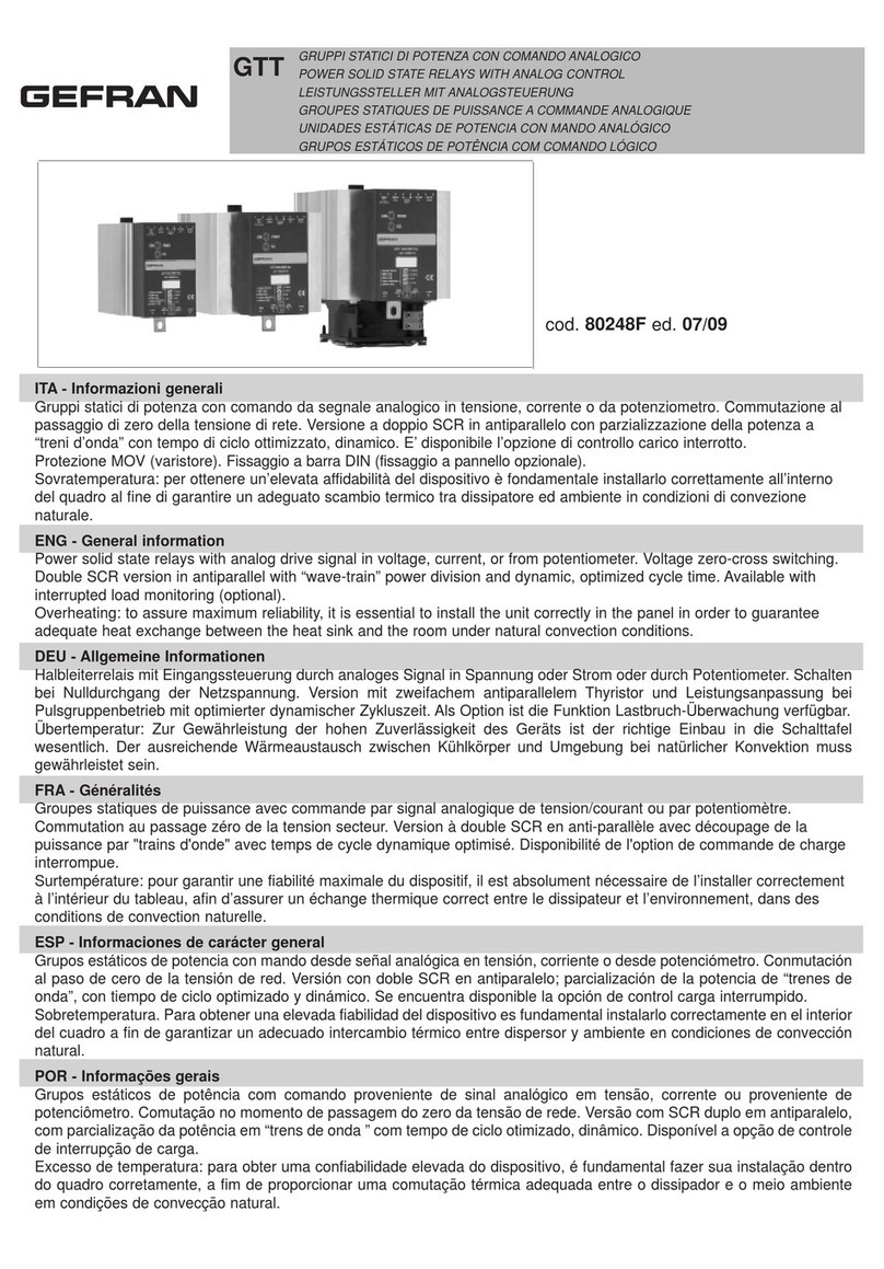
gefran GTT 25/230 User manual

gefran

gefran GTT 25/230 User manual

gefran GQ Series User manual

gefran

gefran GQ Series User manual

gefran GQ 15 Series User manual

gefran

gefran GQ 15 Series User manual

gefran GTS-T 10/230 User manual

gefran

gefran GTS-T 10/230 User manual

gefran GT 25 User manual

gefran

gefran GT 25 User manual

gefran GTZ 25 Quick start guide

gefran

gefran GTZ 25 Quick start guide

gefran GTZ-25 Series User manual

gefran

gefran GTZ-25 Series User manual

gefran GQ Series User manual

gefran

gefran GQ Series User manual

Popular Relay manuals by other brands

MICROENER MG30 Operation manual

MICROENER

MICROENER MG30 Operation manual

PR electronics 9202 Series manual

PR electronics

PR electronics 9202 Series manual

Plejd REL-02 installation manual

Plejd

Plejd REL-02 installation manual

Schweitzer Engineering Laboratories SEL-749M instruction manual

Schweitzer Engineering Laboratories

Schweitzer Engineering Laboratories SEL-749M instruction manual

Solem LR-MB installation guide

Solem

Solem LR-MB installation guide

Davin DV-28 manual

Davin

Davin DV-28 manual

Siemens Ohmega 300 Series maintenance

Siemens

Siemens Ohmega 300 Series maintenance

Siemens 7SR242 Duobias Commissioning and maintenance guide

Siemens

Siemens 7SR242 Duobias Commissioning and maintenance guide

Hella marine 5XA 998 572-001 Installation & operating instructions

Hella marine

Hella marine 5XA 998 572-001 Installation & operating instructions

Gewa GL-RJ user manual

Gewa

Gewa GL-RJ user manual

ABB SPAF 140 C User manual and technical description

ABB

ABB SPAF 140 C User manual and technical description

FULTON RM7895A manual

FULTON

FULTON RM7895A manual

WEG CWMC25 quick start guide

WEG

WEG CWMC25 quick start guide

Bticino F40T125A instructions

Bticino

Bticino F40T125A instructions

Siemens SIRIUS 3RB3 B0 Series Original operating instructions

Siemens

Siemens SIRIUS 3RB3 B0 Series Original operating instructions

Fire-Lite CRF-300 installation instructions

Fire-Lite

Fire-Lite CRF-300 installation instructions

Procom ELR Series manual

Procom

Procom ELR Series manual

red lion PM-50 installation guide

red lion

red lion PM-50 installation guide

manuals.online logo
manuals.online logoBrands
  • About & Mission
  • Contact us
  • Privacy Policy
  • Terms and Conditions

Copyright 2025 Manuals.Online. All Rights Reserved.