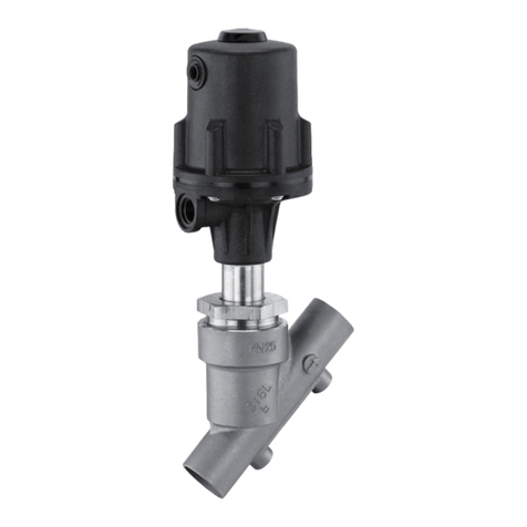
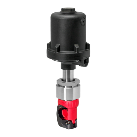
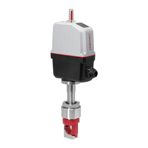
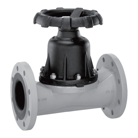
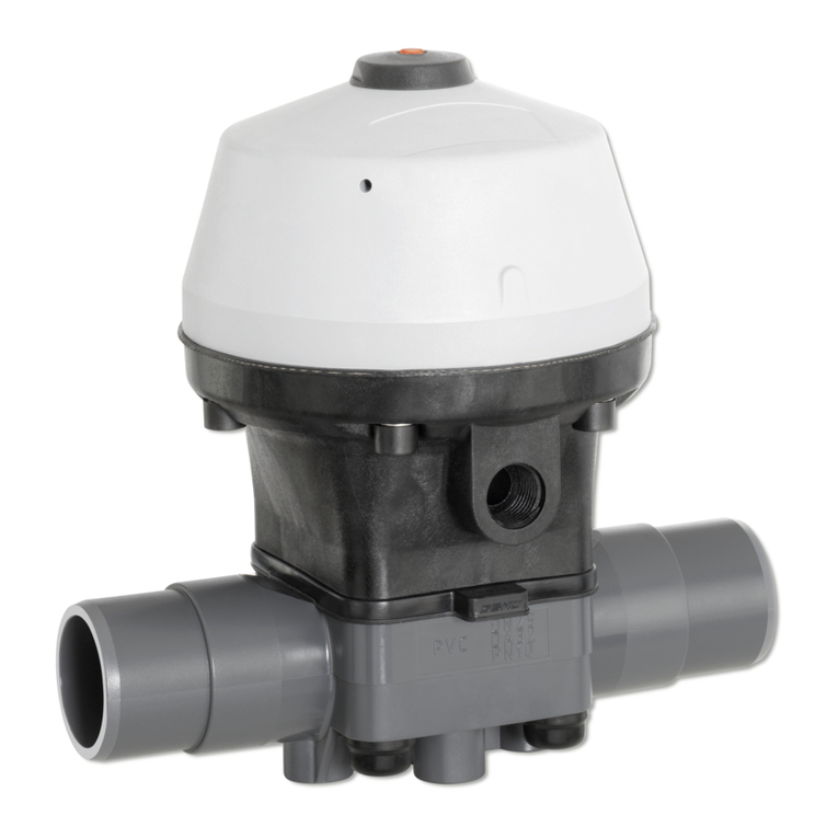
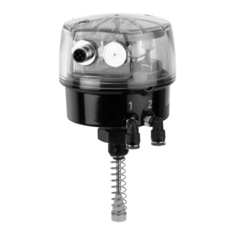
GEM 550 User manual

GEMÜ 550
Pneumatically operated angle seat globe valve
Operating instructions
EN
further information
webcode: GW-550

All rights including copyrights or industrial property rights are expressly reserved.
Keep the document for future reference.
© GEMÜ Gebr. Müller Apparatebau GmbH & Co. KG
03.06.2022
www.gemu-group.com2 / 46GEMÜ 550

Contents
1 General information ............................................. 4
1.1 Information ............................................... 4
1.2 Symbols used ........................................... 4
1.3 Definition of terms .................................... 4
1.4 Warning notes ........................................... 4
2 Safety information ............................................... 5
3 Product description ............................................. 5
3.1 Construction ............................................. 5
3.2 Description ............................................... 5
3.3 Function .................................................... 6
3.4 Control function ........................................ 6
3.5 Flow direction ........................................... 6
3.6 Vent hole in the actuator ........................... 6
3.7 Product label ............................................ 7
4 GEMÜ CONEXO .................................................... 7
5 Correct use .......................................................... 8
6 Order data ........................................................... 9
7 Technical data ..................................................... 11
7.1 Medium .................................................... 11
7.2 Temperature ............................................. 11
7.3 Pressure ................................................... 11
7.4 Product conformity ................................... 16
7.5 Mechanical data ........................................ 18
8 Dimensions .......................................................... 19
8.1 Actuator dimensions ................................. 19
8.2 Installation dimensions ............................. 20
8.3 Body dimensions ...................................... 22
9 Manufacturer's information .................................. 35
9.1 Delivery .................................................... 35
9.2 Packaging ................................................. 35
9.3 Transport .................................................. 35
9.4 Storage ..................................................... 35
10 Installation in piping ............................................ 35
10.1 Use of strainers ........................................ 35
10.2 Preparing for installation .......................... 35
10.3 Installation position .................................. 36
10.4 Installation with clamp connections .......... 36
10.5 Installation with butt weld spigots ............. 36
10.6 Installation with threaded sockets ............. 37
10.7 Installation with threaded spigots ............. 37
10.8 Installation with flanged connection .......... 37
11 Pneumatic connections ....................................... 38
11.1 Use of pilot valves in gas applications ....... 38
12 Commissioning .................................................... 39
13 Operation ............................................................. 39
13.1 Control function 1 ..................................... 39
13.2 Control function 2 ..................................... 39
13.3 Control function 3 ..................................... 39
14 Troubleshooting .................................................. 40
15 Inspection and maintenance ................................ 41
15.1 Components ............................................. 41
15.2 Spare parts ............................................... 41
15.3 Removing the actuator .............................. 42
15.4 Replacing the seals ................................... 42
15.5 Mounting the actuator ............................... 42
16 Removal from piping ............................................ 43
17 Disposal .............................................................. 43
18 Returns ................................................................ 43
19 Declaration of Incorporation according to
2006/42/EC (Machinery Directive) ....................... 44
20 Declaration of conformity according to 2014/68/
EU (Pressure Equipment Directive) ...................... 45
GEMÜ 550www.gemu-group.com 3 / 46

www.gemu-group.com4 / 46GEMÜ 550
1 General information
1.1 Information
- The descriptions and instructions apply to the standard ver-
sions. For special versions not described in this document
the basic information contained herein applies in combina-
tion with any additional special documentation.
- Correct installation, operation, maintenance and repair work
ensure faultless operation of the product.
- Should there be any doubts or misunderstandings, the Ger-
man version is the authoritative document.
- Contact us at the address on the last page for staff training
information.
- A supplement to Directive 2014/34/EU (ATEX Directive) is
included with the product, provided that it was ordered in
accordance with ATEX.
1.2 Symbols used
The following symbols are used in this document:
Symbol Meaning
Tasks to be performed
Response(s) to tasks
– Lists
1.3 Definition of terms
Working medium
The medium that flows through the GEMÜ product.
Control function
The possible actuation functions of the GEMÜ product.
Control medium
The medium whose increasing or decreasing pressure causes
the GEMÜ product to be actuated and operated.
1.4 Warning notes
Wherever possible, warning notes are organised according to
the following scheme:
SIGNAL WORD
Type and source of the danger
Possible
symbol for the
specific
danger
Possible consequences of non-observance.
Measures for avoiding danger.
Warning notes are always marked with a signal word and
sometimes also with a symbol for the specific danger.
The following signal words and danger levels are used:
DANGER
Imminent danger!
▶Non-observance can cause death or
severe injury.
WARNING
Potentially dangerous situation!
▶Non-observance can cause death or
severe injury.
CAUTION
Potentially dangerous situation!
▶Non-observance can cause moderate
to light injury.
NOTICE
Potentially dangerous situation!
▶Non-observance can cause damage to
property.
The following symbols for the specific dangers can be used
within a warning note:
Symbol Meaning
Danger - hot surfaces
Danger - corrosive materials

www.gemu-group.com 5 / 46 GEMÜ 550
2 Safety information
The safety information in this document refers only to an indi-
vidual product. Potentially dangerous conditions can arise in
combination with other plant components, which need to be
considered on the basis of a risk analysis. The operator is re-
sponsible for the production of the risk analysis and for com-
pliance with the resulting precautionary measures and re-
gional safety regulations.
The document contains fundamental safety information that
must be observed during commissioning, operation and main-
tenance. Non-compliance with these instructions may cause:
- Personal hazard due to electrical, mechanical and chemical
effects.
- Hazard to nearby equipment.
- Failure of important functions.
- Hazard to the environment due to the leakage of dangerous
materials.
The safety information does not take into account:
- Unexpected incidents and events, which may occur during
installation, operation and maintenance.
- Local safety regulations which must be adhered to by the
operator and by any additional installation personnel.
Prior to commissioning:
1. Transport and store the product correctly.
2. Do not paint the bolts and plastic parts of the product.
3. Carry out installation and commissioning using trained
personnel.
4. Provide adequate training for installation and operating
personnel.
5. Ensure that the contents of the document have been fully
understood by the responsible personnel.
6. Define the areas of responsibility.
7. Observe the safety data sheets.
8. Observe the safety regulations for the media used.
During operation:
9. Keep this document available at the place of use.
10. Observe the safety information.
11. Operate the product in accordance with this document.
12. Operate the product in accordance with the specifications.
13. Maintain the product correctly.
14. Do not carry out any maintenance work and repairs not de-
scribed in this document without consulting the manufac-
turer first.
In cases of uncertainty:
15. Consult the nearest GEMÜ sales office.
3 Product description
3.1 Construction
1
2
4
5
6
15
14
9
10
11
12
7
13
3
8
Item Name Materials
1 Actuator* Stainless steel
2 Piston
3 CONEXO actuator RFID
chip
(see Conexo information)
4 Union nut
5 Spindle
6 CONEXO body RFID chip
(see Conexo information)
7 Nut
8 Valve body* 1.4408 investment casting
1.4435 investment casting
1.4435 (F316L), forged
body
9 Washer
10 Seat seal* PTFE
11 Valve plug
12 Gasket*
13 Gland packing
14 Compression spring(s)
15 Optical position indicator
*These components are available as spare parts (see operat-
ing instructions chapter "Spare parts (see Chapter 15.2,
page41)").
3.2 Description
The GEMÜ 550 2/2-way angle seat globe valve has a low-
maintenance stainless steel piston actuator and is pneumatic-
ally operated. The valve spindle is sealed by a self-adjusting
3 Product description

www.gemu-group.com6 / 46GEMÜ 550
3 Product description
gland packing providing low-maintenance and reliable valve
spindle sealing even after a long service life. A wiper ring fit-
ted in front of the gland packing protects the seal against con-
tamination and damage.
3.3 Function
The product controls a flowing medium by being closed or
opened by a control medium.
The product has an optical position indicator as standard. The
optical position indicator indicates the OPEN and CLOSED po-
sitions.
Open position Closed position
Fig.2: Optical position indicator
3.4 Control function
The following control functions are available:
Control function 1: Normally closed (NC)
Control function 2: Normally open (NO)
Control function 3: Double acting (DA)
3.5 Flow direction
The flow direction is indicated by an arrow on the valve body.
2/2-way body 2/2-way body
under the seat over the seat
Angle valve bodyAngle valve body
Over the seat
(code M)
Under the seat
(code G)
Under the seat (code G) is the preferred flow direction with in-
compressible liquid media to avoid water hammer
Over the seat (code M) only with control function - Normally
closed (NC)
3.6 Vent hole in the actuator
To vent the control medium, the pneumatic actuator has a
vent hole that is located on the side of the actuator housing
(control function normally closed). In certain areas of applica-
tion (e.g. the foodstuff industry), dirty water or cleaning media
could enter through this vent hole and penetrate the actuator,
thereby adversely affecting correct operation. A special vent
system with lip check valve is available for these applications,
which prevents such functional impairment.The vent hole at
the side is then closed.
Standard vent hole Special vent system K-no.
6996

www.gemu-group.com 7 / 46 GEMÜ 550
3.7 Product label
The product label is located on the actuator. Product label
data (example):
Design in accordance with order data
Device-specific data
Year of manufacture
Item number Traceability number Consecutive number
- XXXXXXXX|YYYY
The month of manufacture is encoded in the traceability num-
ber and can be obtained from GEMÜ. The product was manu-
factured in Germany.
The operating pressure stated on the product label applies to
a media temperature of 20 °C. The product can be used up to
the maximum stated media temperature. You can find the
pressure/temperature correlation in the technical data.
4 GEMÜ CONEXO
Processing industry 4.0 – Traceability and service
Fig.3: GEMÜ 550 with RFID chips
Description
You can use the GEMÜ CONEXO pen to read and process
identification data from devices and components. In conjunc-
tion with the GEMÜ CONEXO app for maintenance engineers,
field data can be collected, processed, and managed and
archived centrally via the GEMÜ CONEXO portal.
Features
- Captive electronic identification of the valve body, actuator
and diaphragm
- Simplified identification and inventory of devices in the field
- Traceability of the components by providing the serial num-
ber
- Electronic supply of product and project-specific document-
ation
- Optimized maintenance processes thanks to a maintenance
log book and photo documentation
Technical specifications - CONEXO PEN:
- Mobile RFID reading device in the form of a pen
- Bluetooth coupling to mobile end devices
- Stylus for touchscreens (smartphone and tablet)
- UHF signal processing
Technical specifications - CONEXO APP:
- Service software for more efficient maintenance
- Available for tablets and smartphones that have the An-
droid or iOS operating system
- High security standards implemented in portal-reader com-
munication
- Workflow template for customizing the maintenance pro-
cess
- Electronically supported diaphragm evaluation and photo
documentation
4 GEMÜ CONEXO

www.gemu-group.com8 / 46GEMÜ 550
5 Correct use
Technical specifications - CONEXO PORTAL:
- Integrated service functions and remote support
- Portable server application with database for Industry 4.0
- Interfaces to maintenance and ERP systems
- High level of IT security thanks to access rights and encryp-
ted data
- Open system (option to integrate third-party devices)
5 Correct use
DANGER
Danger of explosion!
▶Risk of severe injury or death.
●Do not use the product in potentially
explosive zones.
●Only use the product in potentially ex-
plosive zones confirmed in the declara-
tion of conformity.
WARNING
Improper use of the product
▶Risk of severe injury or death.
▶Manufacturer liability and guarantee will be void.
●Only use the product in accordance with the operating
conditions specified in the contract documentation and in
this document.
The product is designed for installation in piping systems and
for controlling a working medium.
1. Use the product in accordance with the technical data.
2. Note the supplement acc. to ATEX
3. Please note the flow direction on the valve body.

6 Order data
The order data provide an overview of standard configurations.
Please check the availability before ordering. Other configurations available on request.
Order codes
1 Type Code
Angle seat globe valve, pneumatically operated,
stainless steel piston actuator
550
2 DN Code
DN 6 6
DN 8 8
DN 10 10
DN 15 15
DN 20 20
DN 25 25
DN 32 32
DN 40 40
DN 50 50
DN 65 65
DN 80 80
3 Body configuration Code
2/2-way body D
Angle valve body E
4 Connection type Code
Spigot
Spigot DIN 0
Spigot EN 10357 series B,
formerly DIN 11850 series 1
16
Spigot EN 10357 series A (formerly DIN 11850 series
2)/DIN 11866 series A
17
Spigot SMS 3008 37
Spigot ASME BPE 59
Spigot ISO 1127/EN 10357 series C/DIN 11866 series B 60
Spigot ANSI/ASME B36.19M schedule 10s 63
Spigot ANSI/ASME B36.19M schedule 40s 65
Threaded connection
Threaded socket DIN ISO 228 1
Threaded socket Rc ISO 7-1,
EN 10226-1, JIS B 0203, BS 21,
end-to-end dimension ETE DIN 3202-4 series M8
3C
Threaded socket NPT,
end-to-end dimension ETE DIN 3202-4 series M8
3D
Threaded spigot DIN ISO 228 9
Flange
Flange EN 1092, PN 25, form B,
face-to-face dimension FTF EN 558 series 1, ISO 5752,
basic series 1
10
Flange EN 1092, PN 25, form B 13
Flange ANSI Class 150 RF 47
Clamp
Clamp ASME BPE,
face-to-face dimension FTF ASME BPE
80
4 Connection type Code
Clamp DIN 32676 series B,
face-to-face dimension FTF EN 558 series 1
82
Clamp DIN 32676 series A,
face-to-face dimension FTF EN 558 series 1
86
Clamp ASME BPE,
face-to-face dimension FTF EN 558 series 1
88
5 Valve body material Code
1.4435, investment casting 34
1.4408, investment casting 37
1.4435 (F316L), forged body 40
1.4435, investment casting C2
Note: A surface finish from the order code table "K
number" must be specified for valve body material C2.
6 Seat seal Code
PTFE 5
PTFE, glass fibre reinforced 5G
PTFE
FDA-compliant, USP class VI
5P
7 Control function Code
Normally closed (NC) 1
Normally open (NO) 2
Double acting (DA) 3
8 Actuator version Code
Actuator size 0G1 0G1
Actuator size 0M1 0M1
Actuator size 1G1 1G1
Actuator size 1M1 1M1
Actuator size 2G1 2G1
Actuator size 2M1 2M1
Actuator size 3G1 3G1
Actuator size 3M1 3M1
Actuator size 4G1 4G1
Actuator size 5G1 5G1
9 Type of design Code
Without
For higher operating temperatures 2023
Special vent system integrated in actuator 6996
Ra ≤ 0.6 μm (25 μinch) for media wetted surfaces,
in accordance with ASME BPE SF2 + SF3
mechanically polished internal
1903
Ra ≤ 0.8 µm (30 µinch) for media wetted surfaces,
in accordance with DIN 11866 H3,
mechanically polished internal
1904
Ra ≤ 0.4 μm (15 μinch) for media wetted surfaces,
in accordance with DIN 11866 H4, ASME BPE SF1
mechanically polished internal
1909
6 Order data
www.gemu-group.com 9 / 46 GEMÜ 550

9 Type of design Code
Ra ≤ 0.6 μm for media wetted surfaces,
in accordance with ASME BPE SF6,
electropolished internal/external
1953
Ra ≤ 0.8 μm for media wetted surfaces,
in accordance with DIN 11866 HE3,
electropolished internal/external
1954
Ra ≤ 0.4 μm for media wetted surfaces,
in accordance with DIN 11866 HE4/ASME BPE SF5,
electropolished internal/external
1959
10 Special version Code
Without
Certified to DIN EN 161, class A G
Special version for oxygen,
maximum medium temperature: 60°C,
media wetted seal materials and auxiliary materials with
BAM testing
S
11 CONEXO Code
Without
Order codes
Ordering option Code Description
1 Type 550 Angle seat globe valve, pneumatically operated,
stainless steel piston actuator
2 DN 15 DN 15
3 Body configuration D 2/2-way body
4 Connection type 1 Threaded socket DIN ISO 228
5 Valve body material 37 1.4408, investment casting
6 Seat seal 5 PTFE
7 Control function 1 Normally closed (NC)
8 Actuator version 1G1 Actuator size 1G1
9 Type of design Without
10 Special version G Certified to DIN EN 161, class A
11 CONEXO Without
6 Order data
www.gemu-group.com10 / 46GEMÜ 550

7 Technical data
7.1 Medium
Working medium: Corrosive, inert, gaseous and liquid media which have no negative impact on the physical and
chemical properties of the body and seal material.
Control medium: Inert gases
Max. permissible viscos-
ity:
600 mm²/s (cSt)
Other versions for lower/higher temperatures and higher viscosities on request.
7.2 Temperature
Media temperature: -10 — 180 °C
for special function G: -10 – 60 °C
with special function S: -10 – 60 °C
Ambient temperature: -10 — 60 °C
Control medium temper-
ature:
0 — 60 °C
Storage temperature: -30 — 60 °C
7.3 Pressure
Operating pressure: Control function 1 (NC) - Flow direction under the seat
Actuator ver-
sion code
0G1 1G1 2G1 3G1 4G1 5G1
DN
610.0 - - - - -
810.0 10.0 - - - -
10 10.0 10.0 22.0 - - -
15 10.0 10.0 22.0 - - -
20 - 6.0 12.0 25.0 - -
25 - 3.5 7.0 16.0 25.0 -
32 - - 4.0 10.0 18.0 25.0
40 - - 2.5 6.0 12.0 20.0
50 - - - 3.0 7.0 15.0
65 - - - - - 10.0
80 - - - - - 7.0
All pressures are gauge pressures. When the flow is over the seat (M), there may be the danger of water ham-
mer with liquid media! For max. operating pressures the pressure/temperature correlation must be observed.
GEMÜ 550www.gemu-group.com 11 / 46
7 Technical data

Operating pressure: Control function 1 (NC) - Flow direction over the seat
Actuator ver-
sion code
0M1 1M1 2M1 3M1
DN
610.0 - - -
810.0 10.0 - -
10 10.0 10.0 - -
15 10.0 10.0 10.0 -
20 - 10.0 10.0 10.0
25 - 10.0 10.0 10.0
32 - - 10.0 10.0
40 - - 8.0 10.0
50 - - 5.0 10.0
65 ----
80 ----
All pressures are gauge pressures. When the flow is over the seat (M), there may be the danger of water ham-
mer with liquid media! For max. operating pressures the pressure/temperature correlation must be observed.
Pressure rating: PN 16
www.gemu-group.com12 / 46GEMÜ 550
7 Technical data

Control pressure: Flow direction: under the seat
Actuator version
code
Control function 1 normally
closed (NC)
Control function 2 and 3
normally open (NO) and double
acting (DA) (NC)
0G1 4 – 8 bar
0
1
5 10 15 20 25
2
3
4
5
6
8
DN 6 / 8 / 10 / 15
7
Control pressure [bar]
Operating pressure [bar]
1G1 4 – 8 bar
0
1
5 10 15 20 25
2
3
4
5
6
8
DN 20DN 25
DN 8-15
7
Control pressure [bar]
Operating pressure [bar]
2G1 4 – 8 bar
0
1
5 10 15 20 25
2
3
4
5
6
8
DN 20
DN 25
DN 15
DN 40 DN 32
7
Control pressure [bar]
Operating pressure [bar]
3G1 4 – 8 bar
0
1
5 10 15 20 25
2
3
4
5
6
8
DN 20
DN 25
DN 40
DN 32
DN 50
7
Control pressure [bar]
Operating pressure [bar]
4G1 4 – 8 bar
0
1
5 10 15 20 25
2
3
4
5
6
8
DN 40
DN 32
DN 50
7
Control pressure [bar]
Operating pressure [bar]
5G1 5 – 8 bar
0
1
5 10 15 20 25
2
3
4
5
6
8
DN 80
DN 65
DN 40
DN 32
DN 50
7
Control pressure [bar]
Operating pressure [bar]
GEMÜ 550www.gemu-group.com 13 / 46
7 Technical data

Control pressure: Flow direction: over the seat
Actuator version
code
Control function 1 normally closed (NC)
0M1 5 – 8 bar
0
1
2 4 6 8 10
2
3
4
5
6
7
DN 6 / 8 / 10 / 15
Control pressure [bar]
Operating pressure [bar]
1M1 5 – 8 bar
0
1
2 4 6 8 10
2
3
4
5
6
7
DN 20
DN 8-15
DN 25
Control pressure [bar]
Operating pressure [bar]
2M1 5 – 8 bar
0
1
2 4 6 8 10
2
3
4
5
6
7
DN 20
DN 15
DN 25
DN 32
DN 40DN 50
Control pressure [bar]
Operating pressure [bar]
3M1 5 – 8 bar
0
1
2 4 6 8 10
2
3
4
5
6
7
DN 20
DN 25
DN 40
DN 32
DN 50
Control pressure [bar]
Operating pressure [bar]
www.gemu-group.com14 / 46GEMÜ 550
7 Technical data

Filling volume: Actuator version
code
Filling volume Piston diameter
0G1, 0M1 0.006 dm³ 28 mm
1G1, 1M1 0.025 dm³ 42 mm
2G1, 2M1 0.084 dm³ 60 mm
3G1, 3M1 0.245 dm³ 80 mm
4G1 0.437 dm³ 100 mm
5G1 0.798 dm³ 130 mm
Leakage rate: Leakage rate A to P11/P12 EN 12266-1
Pressure/temperature
correlation:
Connection
types
code 1)
Material
code 2)
Max. allowable operating pressures in bar at temperature in °C )
RT 100 150 200 250 300
1, 9, 17, 37,
60, 63, 3C,
3D
37 25.0 23.8 21.4 18.9 17.5 16.1
0, 16, 17, 37,
59, 60, 65
34 25.0 24.5 22.4 20.3 18.2 16.1
13 (DN 15 -
DN 50)
34 25.0 23.6 21.5 19.8 18.6 17.2
80, 88 (DN
15 - DN 40)
34 25.0 21.2 19.3 * - - -
80, 88 (DN
50 - DN 80)
34 16.0 16.0 16.0 * - - -
82 (DN 15 -
DN 32)
34 25.0 21.2 19.3 * - - -
82 (DN 40 -
DN 65)
34 16.0 16.0 16.0 * - - -
86 (DN 15 -
DN 40)
34 25.0 21.2 19.3 * - - -
86 (DN 50 -
DN 65)
34 16.0 16.0 16.0 * - - -
10 (DN 15 -
DN 50)
37 25.0 25.0 22.7 21.0 19.8 18.5
47 (DN 15 -
DN 50)
34 15.9 13.3 12.0 11.1 10.2 9.7
0, 16, 17, 59,
60
40 25.0 20.6 18.7 17.1 15.8 14.8
17, 59, 60 C2 25.0 21.2 19.3 17.9 16.8 15.9
* max. temperature 140 °C
All pressures are gauge pressures.
The valves may be used to -10 °C
GEMÜ 550www.gemu-group.com 15 / 46
7 Technical data

Pressure/temperature
correlation:
1) Connection type
Code 0: Spigot DIN
Code 1: Threaded socket DIN ISO 228
Code 1A: Spigot DIN 11866 series A
Code 1B: Spigot DIN 11866 series B
Code 3C: Threaded socket Rc ISO 7-1, EN 10226-1, JIS B 0203, BS 21, end-to-end dimension ETE DIN 3202-4
series M8
Code 3D: Threaded socket NPT, end-to-end dimension ETE DIN 3202-4 series M8
Code 9: Threaded spigot DIN ISO 228
Code 10: Flange EN 1092, PN 25, form B, face-to-face dimension FTF EN 558 series 1, ISO 5752, basic
series 1
Code 13: Flange EN 1092, PN 25, form B
Code 16: Spigot EN 10357 series B, formerly DIN 11850 series 1
Code 17: Spigot EN 10357 series A (formerly DIN 11850 series 2)/DIN 11866 series A
Code 18: Spigot DIN 11850 series 3
Code 37: Spigot SMS 3008
Code 47: Flange ANSI Class 150 RF
Code 59: Spigot ASME BPE
Code 60: Spigot ISO 1127/EN 10357 series C/DIN 11866 series B
Code 80: Clamp ASME BPE, face-to-face dimension FTF ASME BPE
Code 82: Clamp DIN 32676 series B, face-to-face dimension FTF EN 558 series 1
Code 86: Clamp DIN 32676 series A, face-to-face dimension FTF EN 558 series 1
Code 88: Clamp ASME BPE, face-to-face dimension FTF EN 558 series 1
2) Valve body material
Code 34: 1.4435, investment casting
Code 37: 1.4408, investment casting
Code 40: 1.4435 (F316L), forged body
Code C2: 1.4435, investment casting
Kv values: DN Butt weld spigot
DIN 11850
Butt weld spigot
DIN 11866
Threaded socket
DIN ISO 228
61.6 - -
81.8 2.2 -
10 2.4 4.5 4.5
15 2.4 5.5 5.4
20 - 11.7 10.0
25 - 20.5 15.2
32 - 33.0 23.0
40 - 51.0 41.0
50 - 61.0 68.0
65 - 110.0 95.0
80 - 117.0 130.0
Kv values in m³/h
Kv values determined in accordance with EN 60534. The Kv value data refers to control function 1 (NC) and the
largest actuator for each nominal size. The Kv values for other product configurations (e.g. other connection
types or body materials) may differ.
7.4 Product conformity
Food: Regulation (EC) No. 1935/2004*
Regulation (EC) No. 10/2011*
FDA*
* depending on version and/or operating parameters
Pressure Equipment Dir-
ective:
2014/68/EU
Machinery Directive: 2006/42/EC
www.gemu-group.com16 / 46GEMÜ 550
7 Technical data

Gas: EN 161
EN 16678
Gas identification: Valve group: 2
Valve class: A
Explosion protection: ATEX (2014/34/EU) on request
GEMÜ 550www.gemu-group.com 17 / 46
7 Technical data

7.5 Mechanical data
Weight: Actuator
DN Actuator size
012345
60.24 - - - - -
80.24 0.62 0.90 - - -
10 0.24 0.62 0.90 - - -
15 0.24 0.66 0.97 - - -
20 - 0.73 1.00 1.70 - -
25 - - 1.10 1.80 3.20 -
32 - - 1.30 2.00 3.40 6.50
40 - - 1.60 2.10 3.50 6.60
50 - - - 2.30 3.70 6.80
65 - - - - - 7.40
80 - - - - - 8.10
Weights in kg
Body
DN Spigot
K514
Threaded
socket
Threaded
spigot
Flange
K514
Clamp
Connection types code
0, 16, 17, 37, 59,
60, 63, 65
1 9 10, 13, 47 80, 82, 86, 88
60.12 - 0.14 - -
80.12 0.25 0.12 - -
10 0.12 0.25 0.14 - -
15 0.16 0.25 0.14 - -
10 0.25 0.25 - - -
15 0.24 0.35 0.31 1.80 0.37
20 0.50 0.35 0.50 2.50 0.63
25 0.50 0.35 0.65 3.10 0.63
32 0.90 0.75 1.00 4.60 1.08
40 1.10 0.98 1.30 5.10 1.28
50 1.80 1.70 1.80 7.20 2.07
65 3.40 3.20 3.40 - 3.69
80 4.20 4.10 4.40 - 4.60
Weights in kg
www.gemu-group.com18 / 46GEMÜ 550
7 Technical data

8 Dimensions
8.1 Actuator dimensions
M
B
A2
GG
Hmax
45°
B
M
GH
max
G
45°
Actuator size 0, 1 Actuator size 2 - 5
Actuator size øB M H max* G A2
032.0 M 12 x 1 6.0 M 5 35.4
146.0 M 16 x 1 12.0 G 1/8 53.0
263.0 M 16 x 1 22.0 G 1/8 -
384.0 M 16 x 1 28.0 G 1/4 -
4104.0 M 22 x 1.5 32.0 G 1/4 -
5135.0 M 22 x 1.5 41.0 G 1/4 -
Dimensions in mm
H max*: dependent on nominal size
GEMÜ 550www.gemu-group.com 19 / 46
8 Dimensions

8.2 Installation dimensions
8.2.1 Valve with 2/2-way body
CT
45°
LA
SW1
45°
G
Actuator size 0 1 2 3 4 5
DN SW G CT/LA CT/LA CT/LA CT/LA CT/LA CT/LA
6 24 - 91.0 - - - - -
8 24 - 91.0 - - - - -
10 24 - 91.0 - - - - -
15 24 - 91.0 - - - - -
8 36 - - 134.0 171.0 - - -
10 36 - - 134.0 171.0 - - -
15 36 M 34 x 1.5 - 137.0 174.0 - - -
20 41 M 40 x 1.5 - 143.0 180.0 198.0 - -
25 46 M 45 x 1.5 - - 184.0 202.0 235.0 -
32 55 M 52 x 1.5 - - 192.0 210.0 243.0 269.0
40 60 M 60 x 2.0 - - 187.0 215.0 248.0 274.0
50 55 M 72 x 2.0 - - - 223.0 256.0 282.0
65 75 M 90 x 2.0 - - - - - 295.0
80 75 M 105 x 2.0 - - - - - 312.0
Dimensions in mm
The specified dimensions refer to control function 1 (normally closed NC).
The dimensions are smaller for control function 2 (normally open NO).
www.gemu-group.com20 / 46GEMÜ 550
8 Dimensions
Other manuals for 550
2
Table of contents
Other GEM Control Unit manuals
Popular Control Unit manuals by other brands

Ossur
Ossur Icelock Alloy 4-Hole 674 Instructions for use

Primus Wind Power
Primus Wind Power 2-ARAC-103 instruction manual

Parker
Parker DINCon II Installation, operating, & maintenance instructions

GF
GF 582 instruction manual

NI
NI PXIe-8383mc Getting started guide

DMP Electronics
DMP Electronics 893A installation guide