8 Continuation of Actuator version Code
Actuator, pneumatic, single acting, clockwise rota-
tion, spring closing,
SC0220U 6F07/10 S22
SU22KD
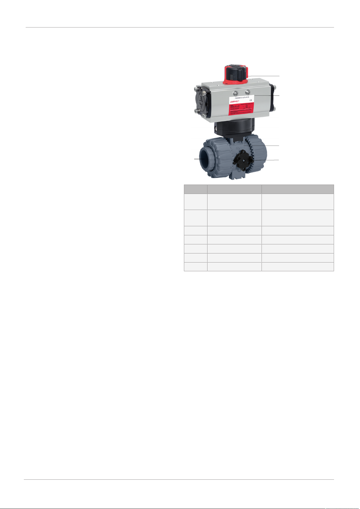
Actuator GEMÜ 9415
GEMÜ actuator, pneumatic, size 0, piston diameter
50 mm
0
GEMÜ actuator, pneumatic, size 1, piston diameter
70 mm
1
9 Actuator particulars Code
Gen. industrial version,
body alu, anodising layer 25-35µm, end caps alu,
powder coated,
shaft C steel + ENP, bolts A2
0
10 Ball config./port position Code
2/2-way body
R ball (control ball)
for 0°- 90° control range
linear control characteristic between port position
and percentage flow rate
R
Multi-port version
L-port, standard end position "Open", connection 2
and 3 open,
L-port, standard end position "Closed", connection
1 and 3 open
L
10 Continuation of Ball config./port position Code
T-port, standard end position "Open", connection 1,
2 and 3 open,
T-port, standard end position "Closed", connection
1 and 3 open
T
T-port, end position "Open", connection 1 and 3
open,
T-port, end position "Closed", connection 1 and 2
open
2
T-port, end position "Open", connection 1 and 2
open,
T-port, end position "Closed", connection 2 and 3
open
3
T-port, end position "Open", connection 2 and 3
open,
T-port, end position "Closed", connection 1, 2 and 3
open
4
L-port, end position "Open", connection 1 and 3
open,
L-port, end position "Closed", connection 1 open
6
11 Type of design Code
Without
Insert in PE 1187
12 CONEXO Code
without
Integrated RFID chip for electronic identification
and traceability
C
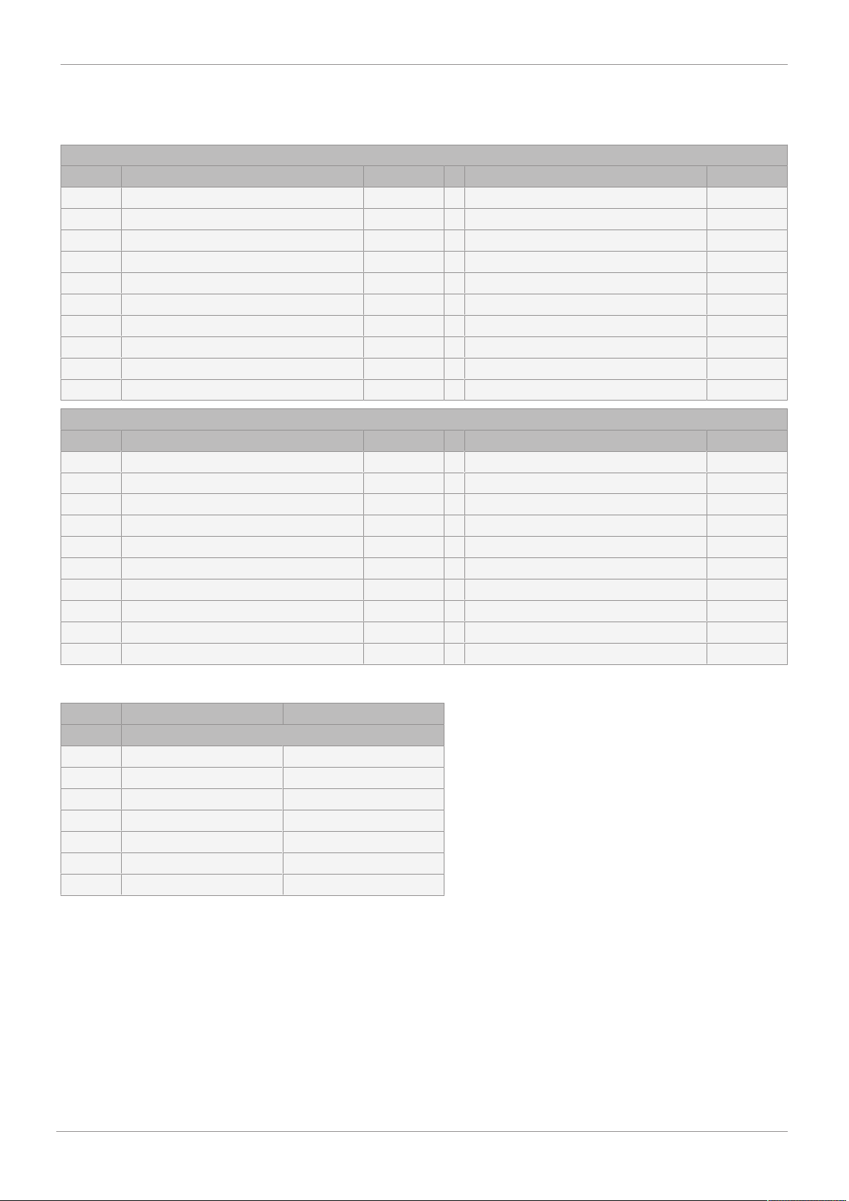
Order example
Order option Code Description
1 Type 710 Ball valve, plastic, pneumatically operated
2 DN 15 DN 15
3 Body configuration M Multi-port version
4 Connection type 33 Union end with inch insert - BS (socket)
5 Ball valve material 1 PVC-U, grey
6 Seal material 14 EPDM
7 Control function 3 Double acting (DA)
8 Actuator version BU02AN Actuator, pneumatic, double acting, clockwise rotation,
ADA0020U F03/05 S09
9 Actuator particulars 0 Gen. industrial version,
body alu, anodising layer 25-35µm, end caps alu, powder coated,
shaft C steel + ENP, bolts A2
10 Ball config./port position L L-port, standard end position "Open", connection 2 and 3 open,
L-port, standard end position "Closed", connection 1 and 3 open
11 Type of design Without
12 CONEXO without
7 Order data
www.gemu-group.com 9 / 44 GEMÜ 710