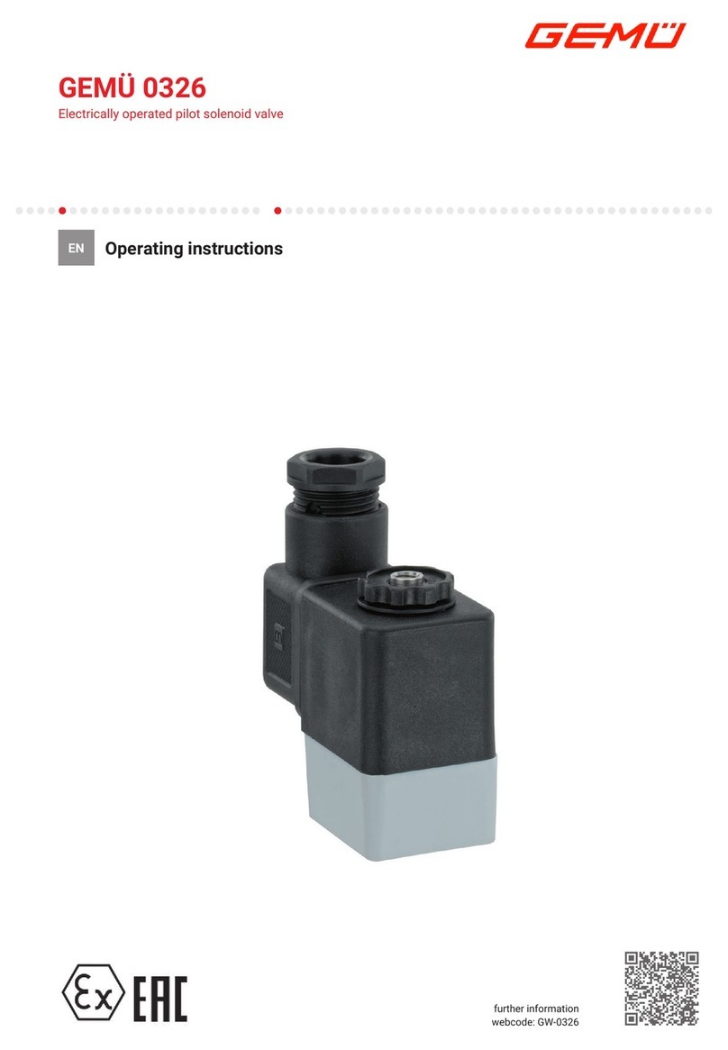
GEM 8500 User manual

GEMÜ 8500
Electrically operated pilot solenoid valve
Operating instructions
EN
further information
webcode: GW-8500

All rights including copyrights or industrial property rights are expressly reserved.
Keep the document for future reference.
© GEMÜ Gebr. Müller Apparatebau GmbH & Co. KG
08.01.2021
www.gemu-group.com2 / 24GEMÜ 8500

Contents
1 General information .................................................. 4
1.1 Information .......................................................... 4
1.2 Symbols used ...................................................... 4
1.3 Definition of terms .............................................. 4
1.4 Warning notes ..................................................... 4
2 Safety information .................................................... 5
3 Product description ................................................... 5
3.1 Construction ........................................................ 5
3.2 Description ........................................................... 5
3.3 Function ............................................................... 5
4 Correct use ............................................................... 6
5 Order data ................................................................. 7
5.1 Order codes ......................................................... 7
5.2 Order example ..................................................... 7
6 Technical data .......................................................... 8
6.1 Medium ................................................................ 8
6.2 Temperature ........................................................ 8
6.3 Pressure ............................................................... 8
6.5 Mechanical data .................................................. 8
6.6 Electrical data ...................................................... 8
7 Dimensions ............................................................... 9
7.1 Standard version ................................................. 9
7.2 NAMUR version ................................................... 9
7.3 NAMUR flex plate ................................................ 9
7.4 Interlinking system .............................................. 10
7.4.1 Individual parts ....................................... 10
7.4.2 Mounted versions .................................. 11
7.5 Solenoid ............................................................... 12
8 Manufacturer's information ....................................... 13
8.1 Delivery ................................................................ 13
8.2 Transport ............................................................. 13
8.3 Storage ................................................................. 13
8.4 Scope of delivery ................................................. 13
9 Assembly .................................................................. 13
10 Pneumatic connection ............................................... 14
10.1 Circuit diagram .................................................... 14
11 Electrical connection ................................................. 15
11.1 Manual override ................................................... 16
12 Interlinking system .................................................... 17
12.1 3/2-way design .................................................... 17
12.2 5/2-way design .................................................... 17
13 Commissioning ......................................................... 18
14 Fault clearance .......................................................... 19
15 Inspection and maintenance ...................................... 20
15.1 Solenoid coil replacement .................................. 20
16 Disassembly .............................................................. 20
17 Disposal .................................................................... 20
18 Returns ..................................................................... 21
19 Declaration of conformity according to 2014/68/EU
(Pressure Equipment Directive) ................................. 22
20 Declaration of conformity in accordance with
2014/35/EU (Low Voltage Directive) and 2014/30/EU
(EMC Directive) ......................................................... 23
GEMÜ 8500www.gemu-group.com 3 / 24
www.gemu-group.com4 / 24GEMÜ 8500
1 General information
1.1 Information
•The descriptions and instructions apply to the standard ver-
sions. For special versions not described in this document
the basic information contained herein applies in combina-
tion with any additional special documentation.
•Correct installation, operation, maintenance and repair work
ensure faultless operation of the product.
•Should there be any doubts or misunderstandings, the Ger-
man version is the authoritative document.
•Contact us at the address on the last page for staff training
information.
1.2 Symbols used
The following symbols are used in this document:
Symbol Meaning
Tasks to be performed
Response(s) to tasks
– Lists
1.3 Definition of terms
Working medium
The medium that flows through the GEMÜ product.
1.4 Warning notes
Wherever possible, warning notes are organised according to
the following scheme:
SIGNAL WORD
Type and source of the danger
Possible
symbol for the
specific
danger
Possible consequences of non-observance.
Measures for avoiding danger.
Warning notes are always marked with a signal word and
sometimes also with a symbol for the specific danger.
The following signal words and danger levels are used:
DANGER
Imminent danger!
▶Non-observance can cause death or
severe injury.
WARNING
Potentially dangerous situation!
▶Non-observance can cause death or
severe injury.
CAUTION
Potentially dangerous situation!
▶Non-observance can cause moderate
to light injury.
NOTICE
Potentially dangerous situation!
▶Non-observance can cause damage to
property.
The following symbols for the specific dangers can be used
within a warning note:
Symbol Meaning
Danger – high voltage
Danger - hot surfaces

www.gemu-group.com 5 / 24 GEMÜ 8500
2 Safety information
The safety information in this document refers only to an indi-
vidual product. Potentially dangerous conditions can arise in
combination with other plant components, which need to be
considered on the basis of a risk analysis. The operator is re-
sponsible for the production of the risk analysis and for com-
pliance with the resulting precautionary measures and re-
gional safety regulations.
The document contains fundamental safety information that
must be observed during commissioning, operation and main-
tenance. Non-compliance with these instructions may cause:
•Personal hazard due to electrical, mechanical and chemical
effects.
•Hazard to nearby equipment.
•Failure of important functions.
•Hazard to the environment due to the leakage of dangerous
materials.
The safety information does not take into account:
•Unexpected incidents and events, which may occur during
installation, operation and maintenance.
•Local safety regulations which must be adhered to by the
operator and by any additional installation personnel.
Prior to commissioning:
1. Transport and store the product correctly.
2. Do not paint the bolts and plastic parts of the product.
3. Carry out installation and commissioning using trained
personnel.
4. Provide adequate training for installation and operating
personnel.
5. Ensure that the contents of the document have been fully
understood by the responsible personnel.
6. Define the areas of responsibility.
7. Observe the safety data sheets.
8. Observe the safety regulations for the media used.
During operation:
9. Keep this document available at the place of use.
10. Observe the safety information.
11. Operate the product in accordance with this document.
12. Operate the product in accordance with the specifications.
13. Maintain the product correctly.
14. Do not carry out any maintenance work and repairs not de-
scribed in this document without consulting the manufac-
turer first.
In cases of uncertainty:
15. Consult the nearest GEMÜ sales office.
3 Product description
3.1 Construction
4
2
3
1
Item Name Materials
1 Plug PA
2 Coil housing PA
3 Pilot head PA
4 Valve body (AlCuMgSn)
Seal materials
3.2 Description
The GEMÜ 8500 servo assisted 3/2 or 5/2-way pilot solenoid
valve is indirectly controlled. The body is made of aluminium.
The plastic encapsulated coil is detachable. The piston valve
has a soft elastomer seal.
3.3 Function
The GEMÜ 8500 pilot solenoid valve is designed to activate
double or single acting pneumatic cylinder actuators or mem-
brane actuators or other pneumatically operated positioning
elements.
3 Product description

www.gemu-group.com6 / 24GEMÜ 8500
4 Correct use
4 Correct use
DANGER
Danger of explosion!
▶Risk of severe injury or death.
●Use of the pilot solenoid valve in po-
tentially explosive areas is not per-
missible.
●Only use the product in potentially ex-
plosive zones confirmed in the declara-
tion of conformity (ATEX).
WARNING
Improper use of the product
▶Risk of severe injury or death.
▶Manufacturer liability and guarantee will be void.
●Only use the product in accordance with the operating
conditions specified in the contract documentation and in
this document.
1. Use the product in accordance with the technical data.
2. Protect the product from direct weathering.

5 Order data
The order data provide an overview of standard configurations.
Please check the availability before ordering. Other configurations available on request.
Order codes
1 Type Code
Pilot valve 8500
2 Way version Code
3/2-way 32
5/2-way 52
3 NAMUR Code
Standard
Flex plate F
NAMUR N
4 DN Code
DN 7 7
5 Body configuration Code
Multi-port version M
6 Connection type Code
Thread G1/4" G2
7 Valve body material Code
AA-2015,
AlCuMgSn
14
8 Seal material Code
NBR 2
9 Control function Code
Combined spring return 1
Pneumatic spring (ATEX) A
10 Voltage/frequency Code
12 V DC B1
24 V DC C1
24 V/50 - 60 Hz C4
48 V DC D1
110 V/50 - 60 Hz E4
230 V/50 - 60 Hz L4
11 Special version Code
Without
180° rotation R
12 Special version Code
Without
UL approval U
ATEX version X
Order example
Order option Code Description
1 Type 8500 Pilot valve
2 Way version 32 3/2-way
3 NAMUR N NAMUR
4 DN 7 DN 7
5 Body configuration M Multi-port version
6 Connection type G2 Thread G1/4"
7 Valve body material 14 AA-2015,
AlCuMgSn
8 Seal material 2 NBR
9 Control function 1 Combined spring return
10 Voltage/frequency C1 24 V DC
11 Special version Without
12 Special version Without
5 Order data
www.gemu-group.com 7 / 24 GEMÜ 8500

6 Technical data
6.1 Medium
Working medium: Filtered, lubricated or unlubricated compressed air which has no negative impact on the physical
and chemical properties of the valve body and seal material.
Air quality acc. to ISO 8573-1:2010:7-4-4 for particles, water and oil
6.2 Temperature
Media temperature: AC operation: -10 to 50 °C
DC operation: -10 to 60 °C
6.3 Pressure
Operating pressure: 2,5 to 10 bar
Flow rate: 1250 Nl/min
6.4 Product compliance
Machinery Directive: 2006/42/EC
EMC Directive: 2014/30/EU
Explosion protection: Special version X order code
ATEX marking: Gas: II 2G Ex mb IIC T4/T5 Gb
Dust: II 2D Ex mb tb IIIC T95°C, T130°C Db
6.5 Mechanical data
Protection class: IP 65
Installation position: Optional
Weight: 3/2-way standard:
5/2-way standard:
0.21 kg
0.25 kg
3/2-way and 5/2-way
NAMUR:
0.26 kg
6.6 Electrical data
Power consumption: AC operation: 5 VA
DC operation: 3 W
Switching times: 20 ms ± 4 ms
Permissible voltage toler-
ance:
±10 % to VDE 0580
Duty cycle: Continuous duty
Wiring note: Special wiring on request. When using electronic switches and additional wiring, carefully design
out any potential residual currents upon installation.
Electrical connection
type:
Plug, design B
www.gemu-group.com8 / 24GEMÜ 8500
6 Technical data

7 Dimensions
7.1 Standard version
1
0
12
48
G 1/4”
67
40
25
13 22
2
22
13
64
31
24Ø 5,5
3/2-way version 5/2-way version
1
14
48
G 1/4”
67
40
25
13 22
5
22
13
86
3
1
44
Ø 5,5
12
22 24
4 2
0
22
1
Dimensions in mm
7.2 NAMUR version
10
12
48
23 24
1
M5G 1/4”
67
40
32
23
86
13 44 13
7,2
2
3
23
1
0
3/2-way version 5/2-way version
12
14
48
23 24
1
G 1/4”
67
40
32
23
86
13 22
2
4
1
0
M5
22
7,2
1322
5 1 3
Dimensions in mm
7.3 NAMUR flex plate
540
32
50
Ø 5,5
13,5
(13) (13)
24
GEMÜ 8500www.gemu-group.com 9 / 24
7 Dimensions

7.4 Interlinking system
7.4.1 Individual parts
7.4.1.1 3/2-way design
Base plates, modular
Base plate on the left Base plate on the right
38.4 22.3 38.4
25
25
50
50
Dimensions in mm
7.4.1.2 5/2-way design
Base plates, modular
Base plate on the left Base plate on the right
33.375 22.25
25
25
70
70
33.375
Dimensions in mm
www.gemu-group.com10 / 24GEMÜ 8500
7 Dimensions

7.4.2 Mounted versions
7.4.2.1 3/2-way design
38.4
22.25
38.4
25
22
50
34
40
22.25 22.25
22.25
22.25 22.25
27.25 27.25
Ø5.5
Ø7
Ø16M3
16.5
6
25
6
26
G3/8"
Dimensions in mm
7.4.2.2 5/2-way design
22,25
25
22
70
56
40
22,25 22,25
22,25
22,25 22,25
22,25 22,25
Ø5,5
Ø7
Ø16
M3
16,5
5
25
5
25
G3/8"
25
25
Dimensions in mm
GEMÜ 8500www.gemu-group.com 11 / 24
7 Dimensions

7.5 Solenoid
28,2 22
8,5
29,5
Ø16
6
10
14
11
Ø9,15
17,2
12
M3
6,3
1,5
0,8
www.gemu-group.com12 / 24GEMÜ 8500
7 Dimensions

www.gemu-group.com 13 / 24 GEMÜ 8500
8 Manufacturer's information
8.1 Delivery
●Check that all parts are present and check for any damage
immediately upon receipt.
The product's performance is tested at the factory. The scope
of delivery is apparent from the dispatch documents and the
design from the order number.
8.2 Transport
1. Only transport the product by suitable means. Do not drop.
Handle carefully.
2. After the installation dispose of transport packaging ma-
terial according to relevant local or national disposal regu-
lations / environmental protection laws.
8.3 Storage
1. Store the product free from dust and moisture in its ori-
ginal packaging.
2. Avoid UV rays and direct sunlight.
3. Do not exceed the maximum storage temperature (see
chapter "Technical data").
4. Do not store solvents, chemicals, acids, fuels or similar
fluids in the same room as GEMÜ products and their spare
parts.
8.4 Scope of delivery
The pilot solenoid valve is supplied as a separately packed
component. The female threads are sealed with caps.
The following is included in the scope of delivery:
•Pilot solenoid valve with solenoid coil
•Plug
•Flex plate (only on NAMUR flex version (code F))
9 Assembly
DANGER
Risk of electric shock
▶There is a danger of injury or death (if
operating voltage is higher than safe
extra low voltage)!
●Before performing any work on the
GEMÜ product, switch off power and
protect circuit from being switched on
again.
CAUTION
Functional impairment of the pilot solenoid valve by con-
taminated media!
▶The pilot solenoid valve will cease to open or close if the
control apertures are blocked or if the armature is
blocked by dirt.
●The piping system should be cleaned prior to installation
of the pilot solenoid valve.
●Fit a strainer with a mesh size of ≤ 0.25 mm in front of the
valve inlet if the media are contaminated.
●Switch the pilot solenoid valve at least once a month.
CAUTION
Destruction of the pilot solenoid valve by freezable medium!
▶The pilot solenoid valve is not frost-protected.
●Pilot solenoid valves using freezable media should only
be operated above freezing point.
CAUTION
Danger from flow contrary to flow direction!
▶Damage to the pilot solenoid valve.
●Only operate the pilot solenoid valve in flow direction.
●Take precautionary measures in case of expected reverse
flow (e.g. check valve).
Prior to installation:
1. Check the suitability of the pilot solenoid valve prior to
the installation!
See chapter "Technical data".
•Installation work must only be performed by trained person-
nel.
•Use appropriate protective gear as specified in plant oper-
ator's guidelines.
Installation location:
NOTICE
▶Battery mounting with central air supply possible.
•Installation position: Optional.
•Manual override and electrical plug must be accessible.
9 Assembly

www.gemu-group.com14 / 24GEMÜ 8500
10 Pneumatic connection
Installation:
2. Ensure the suitability of the valve for each respective use.
The valve must be appropriate for the piping system oper-
ating conditions (medium, medium concentration, temper-
ature and pressure) and the prevailing ambient conditions.
Check the technical data of the valve and the materials.
3. Shut off plant or plant component.
4. Secure against recommissioning.
5. Depressurize the plant or plant component.
6. Completely drain the plant (or plant component) and let it
cool down until the temperature is below the media vapor-
ization temperature and cannot cause scalding.
7. If necessary, correctly decontaminate, rinse and ventilate
the plant or plant component.
8. If necessary, fit a strainer in front of the valve inlet.
9. Carefully remove the caps from the female threads of
the.pilot solenoid valve.
10. Screw the pilot solenoid valve to the appropriate device
with two screws.
11. Connect the control medium lines (see chapter "Pneu-
matic connection").
12. Connect the cable (see chapter "Electrical connection").
10 Pneumatic connection
NOTICE
▶Connect the control medium lines tension-free and
without any bends or knots! Use appropriate connectors
according to the application.
NOTICE
▶The correct NAMUR plate must be fitted before connect-
ing the control medium connectors (see chapter "NAMUR
plate replacement").
Thread size of the control medium connectors:
G1/4
Fig.1: Connector 8500
Fig.2: Connector 8500N
Item Name
1 Air supply
2 Output
3 Exhaust air
4 Output (for 5/2-way version only)
5 Exhaust air (for 5/2-way version only)
10.1 Circuit diagram
10.1.1 3/2-way standard
12
2
3 1

www.gemu-group.com 15 / 24 GEMÜ 8500
10.1.2 3/2-way NAMUR
3 2
12
3 1
10.1.3 5/2-way standard and NAMUR
14
24
5 1 3
11 Electrical connection
DANGER
Risk of electric shock
▶Risk of injury or death (if operating
voltage is higher than safe extra low
voltage).
▶Electric shock can cause severe burns
and fatal injury.
●Work on electrical connections only by
qualified trained personnel.
●Disconnect the cable from the power
supply before making the electrical
connection.
●Connect the protective earth con-
ductor.
NOTICE
▶Every valve solenoid must have a fuse appropriate for its
rated current (max. 3 times rated current in accordance
with DIN 41571 or IEC 60127-2-1) or a motor protection
switch with short circuit and thermal instantaneous trip
(setting to rated current) connected upstream as protec-
tion against short circuits. This fuse may be located in the
corresponding power supply unit or must be connected
separately upstream. The fuse rated voltage must be
equal to or greater than the specified nominal voltage of
the solenoid. The breaking capacity of the fuse unit must
be equal to or greater than the maximum short-circuit cur-
rent occurring at the site of installation (usually 1500 A).
6
4
5
1
2
3
Fig.3: Electrical connection
1. Disconnect the plant from power supply.
2. Unscrew retaining screw 1.
3. Pull off plug 2 with terminal block 3 from solenoid.
4. Press terminal block 3 carefully out of plug 2.
5. Unscrew cable entry 6.
6. Remove pressure ring 4 and gasket 5.
7. Insert cable through cable entry 6, pressure ring 4, gasket
5 and plug 2.
8. Connect the cable.
Fig.4: Rear of terminal block
Item Name
1 Supply voltage
2 Supply voltage
Earthing
11 Electrical connection

www.gemu-group.com16 / 24GEMÜ 8500
11 Electrical connection
9. Push gasket 5 and pressure ring 4 into plug 2.
10. Insert terminal block 3 again in the plug 2 until it audibly
clicks in position.
11. Screw plug 2 to solenoid with retaining screw1 (max.
0.3Nm).
12. Tighten cable entry 6.
11.1 Manual override
8
Fig.5: Manual override
The pilot solenoid valves are equipped with a manual override
8.
Only actuate the manual override in case of malfunction!
Actuate valve via manual override:
•Turn the rotary screw with a screw driver to position 1 (until
it stops).
Close valve by manual override:
•Turn the rotary screw with a screw driver to position 0 (until
it stops).

12 Interlinking system
12.1 3/2-way design
Base plate on the right
Base plate on the left Base plate modular
Blanking plate Solenoid valve
GEMÜ 850032 7M G214 2 ...
Designation Item
Base plate on the right, 3/2-way 99115411
Base plate on the left, 3/2-way 99115412
Base plate modular, 3/2-way 99115413
Blanking plate 99115653
12.2 5/2-way design
Solenoid valve
GEMÜ 850052 7M G214 2 ...
Blanking plate
Base plate on the left Base plate modular Base plate on the right
Designation Item
Base plate on the right, 5/2-way 99115408
Base plate on the left, 5/2-way 99115409
Base plate modular, 5/2-way 99115410
Blanking plate 99115652
GEMÜ 8500www.gemu-group.com 17 / 24
12 Interlinking system

www.gemu-group.com18 / 24GEMÜ 8500
13 Commissioning
13 Commissioning
CAUTION
Protect against leakage!
●Check the tightness of the media con-
nections prior to commissioning!
●Provide precautionary measures
against exceeding the maximum per-
mitted pressures caused by pressure
surges.
Prior to cleaning or commissioning the plant:
1. Check the tightness and the function of the pilot solenoid
valve.
2. If the plant is new or repair work has just taken place, blow
out the piping system with a fully opened pilot solenoid
valve (to remove any harmful foreign matter).
Cleaning
•The plant operator is responsible for selecting the cleaning
medium and performing the procedure.

www.gemu-group.com 19 / 24 GEMÜ 8500
14 Fault clearance
Error Error cause Troubleshooting
No function Power supply not OK Check power supply and connection with
product label
Solenoid coil faulty Check continuity, replace solenoid coil if
necessary
Operating pressure too high Check operating pressure, reduce if ne-
cessary
Control aperture contaminated Clean pilot solenoid valve, fit strainer in
front if necessary
Armature blocked Clean the armature and the bush
Manual override in position 1 Unlock the manual override as described
in chapter "Manual override"
Pilot solenoid valve leaking Main valve seat leaking Clean main valve seat
14 Fault clearance

www.gemu-group.com20 / 24GEMÜ 8500
15 Inspection and maintenance
WARNING
Danger of burning from hot surfaces!
▶Solenoid coil heats up during opera-
tion.
●Allow the solenoid coil and piping to
cool down before servicing work.
WARNING
The equipment is subject to pressure!
▶Risk of severe injury or death.
●Depressurize the plant.
●Completely drain the plant.
1. Use appropriate protective gear as specified in plant oper-
ator's guidelines.
2. Shut off plant or plant component.
3. Secure against recommissioning.
4. Depressurize the plant or plant component.
NOTICE
●Only use genuine GEMÜ spare parts.
●When ordering spare parts, please state the complete or-
der number of the pilot solenoid valve.
The operator must carry out regular visual examination of the
valves dependent on the operating conditions and the poten-
tial danger in order to prevent leakage and damage. The valve
also has to be checked for wear in the corresponding inter-
vals.
15.1 Solenoid coil replacement
10
2
8
7
Fig.6: Solenoid coil replacement
NOTICE
▶When replacing the solenoid coil, the pilot solenoid valve
cannot be operated electrically, but only manually via the
manual override 8.
1. Disconnect the plug 2 from power supply.
2. Undo the fastening nut 7.
3. Pull the plug 2 off the solenoid coil 10.
4. Place a new solenoid coil 10 on the bush.
5. Place the plug 2 back onto the solenoid coil 3.
6. Tighten the fastening nut 7 manually.
7. Push the plug 2 and gasket onto the solenoid coil 10 and
tighten with the fixing screw (60 Ncm).
16 Disassembly
Disassembly is performed observing the same precautionary
measures as for installation.
1. Disassemble the pilot solenoid valve (see chapter "Install-
ation").
2. Disconnect the pneumatic line(s) (see chapter "Pneumatic
connection").
3. Disconnect the electric wire(s) (see chapter "Electrical
connection").
17 Disposal
1. Pay attention to adhered residual material and gas diffu-
sion from penetrated media.
2. Dispose of all parts in accordance with the disposal regu-
lations/environmental protection laws.
Parts Disposal
Valve bodies, valve covers in accordance with material
identification
Screws, armatures, bushes,
compression springs
as metallic core scrap
O-rings, diaphragms, sealing
and plastic parts
as domestic waste type com-
mercial waste
Solenoid coil as electrical scrap
Flex plate in accordance with material
identification
Table of contents
Other GEM Control Unit manuals

GEM
GEM D480 Victoria Assembly instructions

GEM
GEM 554 Assembly instructions

GEM
GEM 8253 Manual

GEM
GEM 651 Assembly instructions

GEM
GEM B26 User manual

GEM
GEM 550 Assembly instructions

GEM
GEM 687 Assembly instructions

GEM
GEM 687 User manual

GEM
GEM iComLine CleanStar C57 HPW User manual

GEM
GEM eSyDrive R649 User manual
Popular Control Unit manuals by other brands

Emerson
Emerson Fisher Slurry Vee-Ball V300S instruction manual

MuseLab
MuseLab WiFi IoT Robotic Shield quick start guide

Comm Net Systems
Comm Net Systems GMT 125-15A Setup and operation manual

Continental Refrigerator
Continental Refrigerator TCAM1NA2 user manual

GOK
GOK 02600 operating manual

Swift Navigation
Swift Navigation CL230G-P user manual