Gerhardt Vapodest 30 User manual

C. Gerhardt GmbH & Co. KG 1
Please read this instruction manual with care before you start operating the
system
Please observe the safety instructions of this manual, marked with in order to
avoid any dangerous handling!
Vap 30
Order no.: 7630
e5030/95 19.05.2003
Instruction Manual
Vapodest 30

C. Gerhardt GmbH & Co. KG
2
VAPODEST 30
Contents
Safety ........................................................................................... 3
Application as directed ..................................................................3
Safety instructions ........................................................................3
1 Technical description ........................................................ 4
Warranty conditions ...................................................................... 4
Technical data .............................................................................. 4
Operating conditions ..................................................................... 5
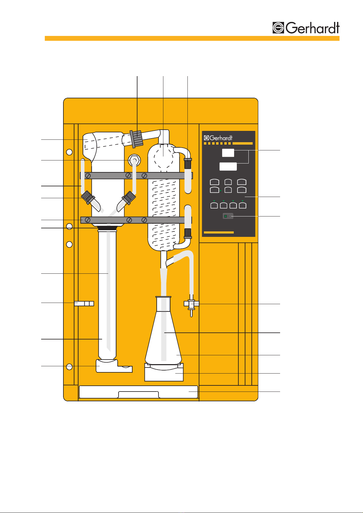
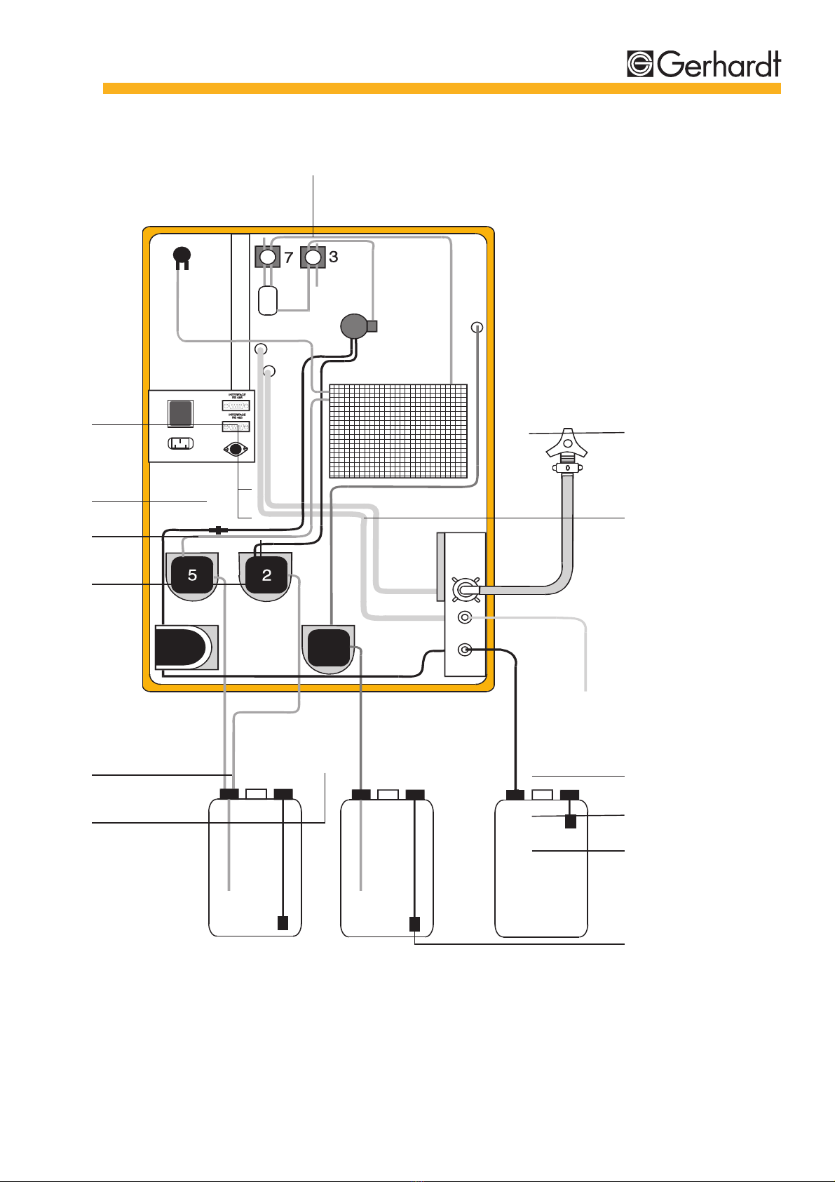
2 Description of the system ................................................. 6
Front view ..................................................................................... 6
Rear view ...................................................................................... 8
3 Delivery .............................................................................10
Check for transport damage .......................................................10
Parts list ......................................................................................10
4 Assembly and installation .............................................. 11
Setup ...........................................................................................11
Setting into operation ..................................................................12
5 Programming the system ................................................ 14
Keyboard .....................................................................................14
Programming the Vapodest 30 ...................................................17
On-line mode ..............................................................................19
6 Operation ..........................................................................21
Safety instructions ......................................................................21
Priming the system .....................................................................21
Test run .......................................................................................22
Distilling a sample .......................................................................23
7 Error messages ................................................................24
8 Maintenance .....................................................................26
Tubing diagram ........................................................................... 26
Spare parts and accessories ......................................................28
Service and cleaning ..................................................................30
Trouble shooting .........................................................................30

C. Gerhardt GmbH & Co. KG 3
Safety
Application as directed
With the Vapodest 30 you have purchased an automatic distillati-
on system for the steam distillation of Kjeldahl digestions and as-
sociated distillations. Automatic addition of NaOH and H
2
O as well
as removal of the sample remains after distillation by suction.
Safety instructions
Make sure that no liquid gets into contact with cable connections
or the interior of the electrical parts of the unit!
Danger of electrical shock!
For repairs on electrical, electronic or mechanical parts please al-
ways contact your agent’s service. Dont’t do repairs by yourself!
Always switch off the apparatus at the mains and pull out the plug
before opening! Danger of electrical shock!
The Vapodest 30 must not be run in damp or hazardous location.
The maximum humidity allowed is 80 %, the maximum ambient
temperature must not exceed 40 °C!
The apparatus must not be exposed to aggressive vapours of aci-
ds, alkalies or solvents.
The apparatus must be used according to this instruction manual.
It is not allowed to supply changes to the apparatus in order to
modify its application.
SAFETY

C. Gerhardt GmbH & Co. KG
4
VAPODEST 30
1 Technical description
Warranty conditions
The Vapodest 30 is manufactured following the high quality guide-
lines of DIN EN ISO 9001.
On the basis of the C. Gerhardt conditions of warranty our pro-
ducts are guaranteed for 1 year, as long as the apparatus is used
in accordance with the instructions mentioned in this manual.
Please note that the semi-consumable parts are excluded from
warranty.
Technical data
Voltage: .................... 230 V AC, 50 Hz
Wattage: ................... 1600 W
Cooling water:........... about 3 litre per distillation minute
Cooling wat. pressure > 1,3 bar
Pump capacity:
-Diaphragm pump .... about 10 ml/s
-Peristaltic pump ...... about 10 ml/s
Store tank: ................ any size, recommended: KAN 30
Micro controller: ........ Single-chip MCU
Display:..................... 5 x 7 LED
Program: ................... 1
Interface: .................. RS 485
Dimensions: .............. 440 x 690 x 340 mm (W x H x D)
Weight: ..................... 27 kg
Baud-rate: ................. 9600
Data-bits: .................. 8
Parity: ....................... No
Start bit: .................... 1
Stop bit: .................... 1
Mode: ....................... Semi-Duplex
User: ......................... Maximum 32
Connection: .............. D-Sub 9-pin acc. to DIN 41 652
Warranty
Distillation
System
Interface

C. Gerhardt GmbH & Co. KG 5
Pin-assignment: ........ 1 – shield
........ 2 – N/C
........ 3 – B driver-Out/receiver-In
........ 4 – N/C
........ 5 – GND
........ 6 – VCC
........ 7 – N/C
........ 8 – A driver-Out/receiver-In
........ 9 – N/C
Operating conditions
Vapodest distillation systems can be run under normal laboratory
conditions.
For the connection to the tap (cold water) a fixed connection with
1/2 inch thread is needed.
TECHNICAL DESCRIPTION
Pin-assignment

C. Gerhardt GmbH & Co. KG
6
VAPODEST 30
2 Description of the system
Front view
Structural components and parts:
1 .... Quick clamping device with wedge
2 .... Kjeldatherm digestion tube, 250/100 ml or flask,
500/750 ml, with enlarged neck or KDD 400/800
3 .... Holder for steam inlet tubing
4 .... PTFE-inlet tubing, steam
5 .... Viton-cone, macro or micro
6 .... Clamping for glassware
7 .... Screw cap GL 18 with silicone seal
8 .... PTFE-inlet tubing, NaOH
9 .... PP-distributor with PP-threaded joint
10 .... Distribution head, glass
11 .... Screw cap GL 32 with silicone seal
12 .... Distillation condenser
13 .... Screw cap GL 14 with plastic screw connection
14 .... Display
15 .... Keyboard, chemical-resistant
16 .... Mains switch, green, illuminated
17 .... Ventilation valve
18 .... Distillate outlet tubing, silicone 8/12 mm
19 .... Erlenmeyer flask
20 .... Platform
21 .... Drip tray
** .... Plexiglass protection door, top (not illustrated)
** .... Plexiglass protection door, bottom (not illustrated)
** .... New, plexiglass protection door, single (not illustrated)

C. Gerhardt GmbH & Co. KG 7
Fig.2.1: Front view Vapodest 30
DESCRIPTION OF THE SYSTEM
1
2
3
4
5
6
7
8
9
10
1211 13
16
17
18
19
20
21
14
15
-
O n - l i n e R e s e t
P r o g R u n
+
T i m e
S t e p
V a p o d e s t
S t e a m
N a O H
H 2 O E m p t y
1 0

C. Gerhardt GmbH & Co. KG
8
VAPODEST 30
Rear view
Description of the connections:
1 .... Diaphragm pump for H
2
O sample:
.... Connection pipe for PVC-tubing 4/7 mm
2 .... Diaphragm pump for H
2
O steam generator:
.... Connection pipe for PVC-tubing 4/7 mm
3 .... Level detector:
Connection socket for diode plug, 3-pin
(level detector for set of tanks KAN 30)
4 .... Mains cable with appliance plug
5 .... Excess current switch, 10A
.... Cuts off in case of excessive current consumption
6 .... RS 485 interface
7 .... Outlet ventilation tubing
8 .... Excess pressure - steam outlet
9 .... Excess temperature fuse
10 .... Cooling water inlet with sieve:
.... Connection thread 3/4 inch for water inlet tubing 10x17
11 .... Water outlet:
.... Connection pipe for PVC-tubing 8/12 mm
12 .... Peristaltic pump for sample suction
.... Connection pipe for Verprene tubing 8/12 mm
13 .... Diaphragm pump for NaOH:
.... Connection pipe for PVC-tubing 8/12 mm

C. Gerhardt GmbH & Co. KG 9
&
$
"
L e v e l - d e t e c t o r
H 2 O
d i s t i l l e d
N a O H S a m p l e
w a s t e
P o w e r
11
Fig.2.2: Rear view Vapodest 30
DESCRIPTION OF THE SYSTEM
4
5
6
2
3
1
7
8
9
10
13
12

C. Gerhardt GmbH & Co. KG
10
VAPODEST 30
3 Delivery
Check for transport damage
Before assembling the instrument please check if the contents of
the box is complete and intact!
In case of any damage, please notify your carrier (post, rail, road)
and obtain an expert’s report!
The exact contents of the delivery can be checked by the follo-
wing list.
Parts list
– Distillation system Vapodest 30, complete
– Tubing set:
1 x Water inlet tube 10/17mm with connections of 1/2 inch and
3/4 inch, 2m
1 x Verprene tube 8/12 mm. 2 m
2 x PVC tube 4/7 mm, 2 m
2 x PVC tube 8/12 mm, 2m
2 x PVC pipe 6 x 1 mm, 420 mm
1 x PVC pipe 10 x 1 mm, 420 mm
– 1 x Mains cable
– 1 x Kjeldatherm digestion tube 250 ml or 100 ml

C. Gerhardt GmbH & Co. KG 11
Installation
4 Assembly and installation
Setup
Please observe the local water and waste regulations and those
of your public water supply enterprise!
Please note that the length of the inlet and outlet tubing is restric-
ted to 2 metres.
The appliance should be located on a fixed laboratory bench, close
to the cold water connection and a drain.
There should be sufficient space for the set of tanks below the
work bench.
Connect the water inlet tubing to a dedicated cold water tap.
The water pressure must be at least 1,3 bar in order to operate the
integrated pressure controller.
The Vapodest 30 comes completely preassembled. Please un-
pack the instrument with care!
1. Place instrument on work bench
2. Unpack accessories.
3. Place set of tanks for distilled water, sodium hydroxide and
sample waste below the bench.
Make sure that the set of tanks are not placed any higher than the
distillation unit!
4. Connect the pump tubes (connections are marked at the rear
of the apparatus) to the PVC-pipes of the chemical tanks:
– Inlet tubing sodium hydroxide (PVC-tubing 8/12 mm)
– Inlet tubing for distilled water steam generator
(PVC-tubing 4/7 mm)
– Inlet tubing for distilled water sample (PVC-tubing 4/7)
5. Connect the water inlet tubing
- Connect water inlet tubing (pressure-proof tissue tubing
10/17 mm) to cooling water inlet and laboratory water supply
INSTALLATION
Tubing
connections

C. Gerhardt GmbH & Co. KG
12
VAPODEST 30
6. Connect the outlet tubing:
– Connect water outlet tubing (PVC-tubing 8/12 mm) to connec-
tion pipe at the rear and place in the drain
– Connect sample waste outlet (Verprene-tubing 8/12 mm) to
pipe at the rear and direct to sample waste tank/drain
Please check the nominal voltage on the type plate before con-
necting to the mains.
7. Mains connection
– Make sure that the mains switch at the front of the instrument
is in position „0“
– Connect the mains cable to the rear appliance plug first
– Connect the mains cable to a shockproof socket
8. Use of the set of tanks KAN 30 (optional)
– Connect the diode plugs of the level detectors to the distribu-
tion box and connect to the socket level detection (at rear)
– Blank off the remaining diode sockets of the distribution box
with the dummy diode plugs enclosed.
9. Excess current switch
– Before you first take the Vapodest into operation make sure
that the excess current switch at the rear is in position 1.
Setting into operation
Attention when working with acids and alkalies! Make sure you
observe the safety instructions concerning work with hazardous
materials!
Always close the plexiglass doors of the distillation unit before
operating!
1. Fill the set of tanks with chemicals:
–H
2
O distilled or demineralized
– NaOH 32 %
2. Turn on the water tap
3. Initial filling of steam generator
– When using the set of tanks KAN 30:
Press the key „+“ ((keep pressed), and switch on the instru-
ment

C. Gerhardt GmbH & Co. KG 13
– When using other reservoirs:
Press the key „-“ (keep pressed), and switch on the instru-
ment
Please note that these key combinations are only used for the
initial filling of the steam generator. For subsequent operati-
ons the instrument is switched on via the mains switch!
– After switching the unit on the pump that fills the steam gene-
rator starts immediately, and the display shows the error mes-
sage „E3“ (lack of water in the steam generator)
– Press key „Run“ (only for initial filling)
The steam generator is filled with water up to a preset level,
which then causes the pump to switch off.
4. Monitoring the status notice on the display:
The Vapodest 30 is now ready for operation.
INSTALLATION

C. Gerhardt GmbH & Co. KG
14
VAPODEST 30
5 Programming the system
Keyboard
The Vapodest 30 can be programmed and controlled via the key-
board of the control panel.
Entry keyboard
Control LED
Control keyboard
Mains switch
Keyboard
Fig 5.1: Control panel keyboard
Display
-
O n - l i n e R e s e t
P r o g R u n
+
T i m e
S t e p
V a p o d e s t
S t e a m
N a O H
H 2 O E m p t y
1 0

C. Gerhardt GmbH & Co. KG 15
Display/Keys Meaning within program mode
Display program step
Time in seconds or minutes,
The Vapodest is delivered with the se-
cond-mode. In order to be able to switch
between the second- and the minute-
mode, please proceed as described:
- Press the key 'Prog' when turning on
the instrument - Display point flashes
Prog: check, memorize and
confirm programm
Run: Start data transfer in
synchronous mode (on-line activated))
„+“: Increasing actual value to
desired value
„-“: Decreasing actual value to
desired value
Reset:
Interruption of programming,
return to start position
Key On-line pressed:
Control LED illuminated,
RS 485 interface is activated
Programming status H2O:
Control LED flashes
Programming status NaOH:
Control LED flashes
Programming status distillation:
control LED flashes
Programming status suction:
control LED flashes
Program mode
PROGRAMMING

C. Gerhardt GmbH & Co. KG
16
VAPODEST 30
Display/Key Meaning in Run mode
Display program step
Display point flashes
Time in seconds or minutes
Display program end
–
Run: Starting and repeating of program
–
–
Reset:
Interruption of program and return
to start position
On-line key pressed:
Control LED illuminated,
RS 485 interface is activated
Program step H2O addition:
Control LED illuminated
Program step NaOH addition:
Control LED illuminated
Program step distillation:
Control LED illuminated
Program step suction:
Control LED illuminated
Run mode

C. Gerhardt GmbH & Co. KG 17
Step Program status Time Confirmation
Start Start position
1 Addition H2O Range:
0 to 30 s
Preset:
5 s
2 Addition NaOH Range:
0 to 30 s
Preset:
12 s
Programming the Vapodest 30
Each Vapodest undergoes a pre-delivery performance test in the
quality assurance department before leaving C. Gerhardt. On arri-
val the machine is supplied with the test program.
If you wish to keep this program, please confirm the program steps
with the „Prog“ key. If changes are required, please press either
the „+“ or „-“ keys at the relevant step, and then store with the
„Prog“ key.
Programming the
distillation system
PROGRAMMING

C. Gerhardt GmbH & Co. KG
18
VAPODEST 30
3 Reaction time Range:
0 to 999 s in
second-mode
or
0 to 99,9 min in
minute-mode
Preset:
0 s
4 Distillation time Range:
0 to 999 s in
second-mode
or
0 to 99,9 min in
minute-mode
Preset:
210 s
4* Power Range:
35 to 100 %
Preset:
100 %
5 Suction Range:
0 to 999 s
Preset:
25 s
Prog. Start position
End
Programming the
distillation system

C. Gerhardt GmbH & Co. KG 19
On-line mode
The RS 485 interface allows quality assurance conforming to ISO/
GLP. It enables up to 32 different instruments (including other
makes) to be connected between each other.
The on-line mode provides the following possibilities:
1. Connection of personal computer for controlling and monito-
ring in conjunction with the GerLab® user program.
2. Connection of PC for controlling and monitoring in conjunction
with a customerised terminal program, i.e., Telix (MS-DOS),
Terminal (for Windows). With the assistance of the interface a
program, based on the customers’ needs, can be written, too.
3. Synchronous working of various equipment. The programming
and controlling is effected via a system, which has been ap-
pointed semi master.
The working instructions for the synchronous mode are as follows:
– Connect all instruments with the interface cables RS 485
– Provide the last unit connected with the terminator AST
– Activate the on-line key of each instrument (control LED illu-
minated)
– Determine the semi master by pressing the keys „+“ (keep
pressed) and on-line (control LED flashes)
By pressing this key-combination once more you can return to the
simple on-line position (Control LED illuminated).
Synchronous mode
Control via PC
PROGRAMMING

C. Gerhardt GmbH & Co. KG
20
VAPODEST 30
– Programme the semi master as described in the previous pa-
ragraph
After having confirmed program step 5 the following is shown
on the display:
– Press the „Run“ key to initiate the data transfer from
the semi master to the connected instruments
– After the termination of the data transfer the programming mode
automatically ends, and the display shows the start position:
Further information about GerBus® and GerLab® can either be
optained from C. Gerhardt GmbH & Co. KG or our appointed
dealer!
Other manuals for Vapodest 30
1
Table of contents
Other Gerhardt Distilling Equipment manuals