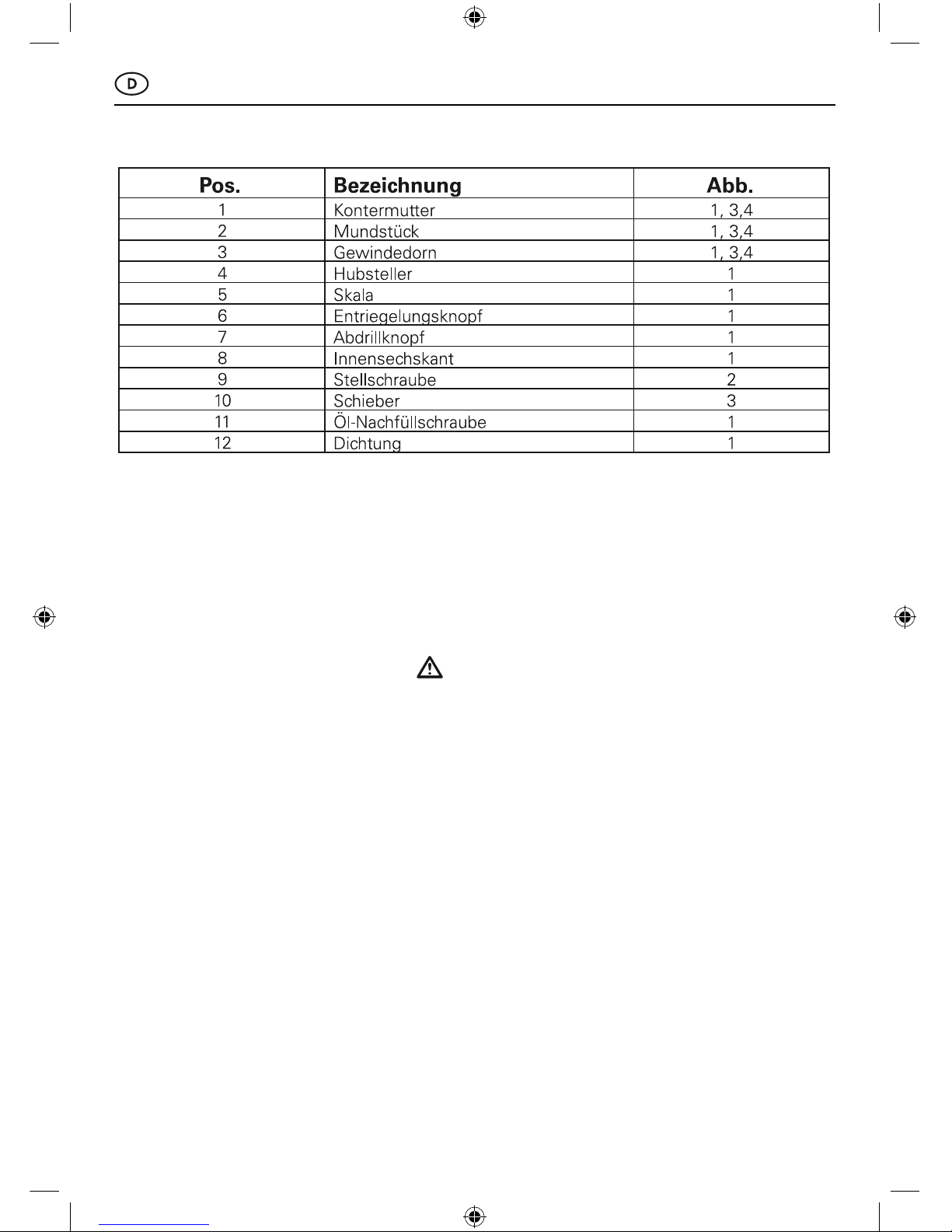
Gesipa FireFox User manual

11/2011 - 1970099


7
Inhaltsverzeichnis
1. Übersicht (Abb. 1-4)
2. Blindnietmutternsetzgerät FireFox®
2.1 Bestimmungsgemäße Verwendung
2.2 Sicherheitshinweise
2.3 Arbeitsbereich
2.4 Technische Daten
2.5 Ausrüstung / Zubehör
3. Inbetriebnahme
3.1 Wechsel des Gewindedornes
3.2 Einstellen der Gewindedornlänge „X“
4. Einstellen des Setzhubes oder der Setzkraft
4.1 Einstellen des Setzhubes
4.2 Einstellen der Setzkraft
5. Arbeitsweise
5.1 Aufdrillen der Mutter
5.2 Setzen der Mutter
5.3 Manuelles Abdrillen der Mutter
6. Wartung und Pflege
7. Behebung von Störungen
8. Umwelthinweise
9. Garantie
10. Konformitätserklärung
Seite
..................................................................... 4
.................................. 8
............................................................ 8
..................................................................... 8
................................................................ 9
......................................................... 9
............................................. 9
............................... 10
................................................. 10
.................................................... 11
......................................................... 11
.............................................................. 12
........................................ 12
..................................................................... 12
........................................................... 13
.......................................................................... 13
........................................................................................ 13
................................................................ 13

8
1. Übersicht (siehe Bild 1 - 4)
2. Blindnietmutternsetzgerät FireFox®
Das Nietgerät darf nur, wie in dieser Betriebs-
anleitung beschrieben, zum Setzen von Blind-
nietmuttern und Blindnietbolzen verwendet
werden.
Die Sicherheitshinweise sind
einzuhalten!
2.1 Bestimmungsgemäße Verwendung
Das Nietgerät ist ausschließlich zum Setzen
von Blindnietmuttern und Blindnietbolzen zu
verwenden.
Beim Aufdrillen und beim Setzen der Mut-
ter besteht bei unsachgemäßer Anwendung
Quetschgefahr für die Finger!
Überlasten Sie das Nietgerät nicht; arbeiten
Sie im angegebenen Leistungsbereich.
Zulässigen Betriebsdruck nicht überschreiten.
Nicht ohne Fügegut nieten.
Anschlussleitungen für die Druckluft regelmä-
ßig auf Festsitz und Dichtheit prüfen.
Bei allen Wartungsarbeiten am Nietgerät,
auch zum Wechseln der Gewindedorne, und
bei Nichtgebrauch ist das Gerät immer vom
Druckluftnetz zu trennen.
Beim Arbeiten mit dem Nietgerät stets Schutz-
brilletragen.PersönlicheSchutzausrüstungwie
Schutzkleidung,Handschuhe,Sicherheitshelm,
rutschfeste Schuhe, Gehörschutz und Siche-
rung gegen Absturz wird empfohlen.
Beim Ablegen das Nietgerät gegen Herunter-
fallen sichern.
Reparaturen sind nur durch eine geeignete
Fachkraft auszuführen. Bei Reparaturen nur
Originalersatzteile verwenden. Im Zweifelsfal-
le ist das Nietgerät unzerlegt an den Lieferer
oder GESIPA®einzusenden.
Vermeiden Sie übermäßigen Kontakt mit Hy-
drauliköl. Falls Hautreizungen auftreten, Haut-
stellen gründlich mit Wasser waschen!
Entsorgung des Hydraulik-Altöls nach den gel-
tenden Umweltvorschriften.
2.2 Sicherheitshinweise
Das Nietgerät ist zum Setzen von Blindniet-
muttern und Blindnietbolzen M3 bis M 12 aller
2.3 Arbeitsbereich
Werkstoffe geeignet.

9
Gewicht: 2,4 kg
Betriebsdruck: 5 bis 7 bar
Gerätehub: max. 10 mm
Schlauchanschluss: Ø6 mm (1/4“)
Luftverbrauch: ca. 2 -4 Liter/Setzvorgang (abhängig von Mutterngröße)
Setzkraft bei 5 bar: 18,5 kN
Hydrauliköl: ca. 30ml (ISO VG 32 bis 46)
Geräuschemission Lpa: 75 dB
Vibration: < 2,5 m/s²
Unsicherheit: K=1 m/s²
Druckluftqualität: gefiltert
2.4 Technische Daten
Gewindedorne und Je nach gewählter Gerätevariante in
Mundstück: Arbeitsposition
Werkzeug: Sechskantschraubendreher SW4
2 Stück Doppelmaulschlüssel SW24/27
Aufhänger: ausziehbar aus Gerätekopf
Hydrauliköl: 1 Flasche Hydrauliköl 100ml
1 Ölnachfüllbehälter
2.5 Ausrüstung/Zubehör
3. Inbetriebnahme
Vor Inbetriebnahme des Nietgerätes ist der passende Gewindedorn mit Mundstück zu mon-
tieren.
• Blindnietgerät vom Druckluftnetz trennen.
• Kontermutter 1 mit Doppelmaulschlüssel
SW27 lösen
• Mundstück 2 mit Kontermutter
1 abschrauben
• Schieber 10 bis zum Anschlag nach
hinten schieben und festhalten
• Gewindedorn 3 ausschrauben
• Neuen Gewindedorn gleicher Größe
(falls verschlissen) oder Gewindedorn
mit passender Gewindegröße bis zum
Anschlag einschrauben.
• Schieber loslassen. Dabei darauf
3.1 Wechsel des Gewindedornes
achten, dass der Gewindedorn sicher
mittels Innensechskant des Schiebers
verriegelt wird. Bei Bedarf den
Gewindedorn leicht zurückschrauben,
bis der Schieber einrastet.
• Zur jeweiligen Gewindegröße
passendes Mundstück mit der
Kontermutter 1 einschrauben und
mittels Doppelmaulschlüssel leicht
kontern.
• Gewindedornlänge „X“ gemäß
Punkt 3.2 einstellen.

10
• Lösen der Kontermutter 1 mittels
Doppelmaulschlüssel
• Durch Drehen des Mundstückes 2 die
Gewindedornlänge „X“ auf die
Mutternlänge einstellen (siehe Bild 4)
• Bei geschlossenen Blindnietmuttern
(Bild 4) Gewindetiefe voll nutzen
3.2 Einstellen der Gewindedornlänge „X“
• Mundstück 2 mit Kontermutter
1 gegen Verstellen sichern
Der eingestellte Setzhub des Nietgerätes
wird durch das Einstellen der Dornlänge nicht
verändert!
4. Einstellen des Setzhubes oder der Setzkraft
Der FireFox®kann entweder mit einem fest eingestellten Setzhub oder mit einer auf die jewei-
lige Mutterngröße abgestimmten Setzkraft betrieben werden.
Wann benutzt man diese Einstellung?
Wenn immer die gleiche Blindnietmutterngröße und -länge in eine gleiche Materialstärke ge-
setzt wird, kann mit einem konstanten Setzhub gearbeitet werden.
4.1 Einstellen des Setzhubes
Die Einstellung des Setzhubes erfolgt
in 4 Schritten:
1. Die Stellschraube 9 (Bild 2) ist mit dem
beiliegenden Sechskantschraubendreher
SW4 bis zum Anschlag einzudrehen
2. Der grüne Entriegelungsknopf 6 wird
vollständig eingedrückt
3. Durch Drehen des Hubstellers 4 wird der
Setzhub mit Hilfe der Skala 5 eingestellt.
(1 Strich der Skala entspricht 1 mm Setzhub)
4. Den grünen Entriegelungsknopf loslassen.
Falls der Entriegelungsknopf 6 nicht
selbständig einrastet, den Hubsteller
vorsichtig drehen, bis der Hubsteller 4
verriegelt ist.
Die Werte für den Setzhub in der folgendenTabelle sind lediglich Richtwerte und stark abhängig
von der Materialstärke! Der einzustellende Setzhub ist durch Versuche mit der exakten Materi-
alstärke zu ermitteln. Für jeden Versuch ist eine neue Mutter zu verwenden!
Richtwerte für den Setzhub

11
4.2 Einstellen der Setzkraft
Wann benutzt man diese Einstellung?
• Wenn eine Blindnietmutterngröße (z.B. M6) in unterschiedlich dicke Materialstärken
gesetzt wird.
• Eine Blindnietmutterngröße mit unterschiedlichen Längen
(z.B. M6x15,5 oder M6x18) in unterschiedlich dicke Materialstärken gesetzt wird.
In diesen Fällen sollte der FireFox®auf eine für
die jeweilige Blindnietmutterngröße (z.B.M6)
geeignete Kraft eingestellt werden. Dadurch
wird sichergestellt, dass alle Blindnietmuttern
einer Abmessung (z.B. M6) auch mit unter-
schiedlichen Mutternlängen immer exakt in
unterschiedlich dicke Materialien gesetzt wer-
den.
Die Einstellung der Setzkraft wird folgender-
maßen durchgeführt:
1. Der grüne Entriegelungsknopf 6 wird
vollständig eingedrückt.
2. Durch Drehen des Hubstellers 4 den
Setzhub auf Maximalhub von 10 mm
einstellen (bis alle Striche der Skala
sichtbar sind).
3. Herausdrehen der Stellschraube 9 (Bild 2)
bis die Vorderkante der Stellschraube 9 ca.
10 mm aus dem Gerätekopf heraussteht.
4. Aufdrillen der zu setzenden Blindnietmutter
(siehe Punkt 4.1).
Die Blindnietmutter in das zu vernietende
Material stecken. Dabei möglichst bei
unterschiedlich dicken Materialien die
dickste Materialstärke wählen.
5. Auslösen eines Setzvorganges durch
Drücken des Betätigungsknopfes. Wird
die Mutter dabei nicht verformt, wird die
Stellschraube jeweils um ca. 1 bis 2
Umdrehungen mit dem Sechskantschrau-
bendreher SW4 eingeschraubt.
(Die Blindnietmutter kann für den Einstell-
vorgang mehrfach benutzt werden, bis eine
exakte Verformung eintritt!)
Durch Einschrauben der Stellschraube 9 wird die Setzkraft des Nietgerätes erhöht; durch
Herausschrauben wird die Setzkraft reduziert!
Man muss sich vorsichtig an die optimale Setzkraft durch Einschrauben der Stellschraube 9
herantasten, in dem der komplette Setzvorgang (Aufdrillen – Setzvorgang starten) solange wie-
derholt wird, bis die Blindnietmutter ausreichend verformt wurde.
5. Arbeitsweise
• Blindnietmutter ohne zu verkanten am
Gewindedorn 3 ansetzen.
• Danach mit der Blindnietmutter fest auf
den Gewindedorn in Richtung Blindniet-
gerät drücken. Der Aufdrillvorgang wird
durch das Andrücken automatisch gestartet.
(Nicht den Betätigungsknopf drücken!)
5.1 Aufdrillen der Mutter
• Die Blindnietmutter während des gesamten
Aufdrillvorganges festhalten, bis die Blind-
nietmutter am Mundstück 2 anliegt.
Der Aufdrillvorgang wird automatisch
beendet.

12
• Aufgedrillte Blindnietmutter bis zum
Anschlag in die Bohrung des Werkstückes
einführen.
• Den Setzvorgang durch Drücken des Betä-
tigungsknopfes starten.
Betätigungsknopf festhalten!
• Nachdem entweder der eingestellte Setz-
hub oder die eingestellte Setzkraft erreicht
5.2 Setzen der Blindnietmutter
wurde (siehe dazu Punkt 4!), wird automa-
tisch der Abdrillvorgang gestartet. Der Ab-
drillvorgang läuft dabei solange, wie der Be-
tätigungsknopf gedrückt wird. Erst nachdem
der Gewindedorn vollständig aus der gesetz-
ten Mutter ausgedrillt wurde, darf der Betäti-
gungsknopf losgelassen werden.
• Wenn z.B. nach einem Setzvorgang der
Betätigungsknopf zu früh losgelassen und
dadurch der Gewindedorn noch nicht voll-
ständig ausgedrillt wurde oder beim Auf-
drillen die Mutter schief angesetzt wurde,
kann durch Drücken des Abdrillknopfes 7
(siehe Bild 1) manuell ein Abdrillvorgang
gestartet werden.
• Kann der Gewindedorn nicht durch Drü-
5.3 Manuelles Abdrillen der Mutter
cken des Abdrillknopfes 7 ausgedrillt werden
(z.B. Gewinde in der Mutter stark deformiert),
kann der Gewindedorn mit der Hand ausge-
drillt werden. Dazu den beiliegenden Sechs-
kantschraubendreher SW4 in den Innen-
sechskant 8 am Luftaustritt des Luftmotors
(siehe Bild 1) einstecken und durch Linksdre-
hung den Gewindedorn lösen.
Der Aufbewahrungsort des Blindnietmuttern-
setzgerätes muss trocken sein.
Bei Bedarf sind verschlissene Gewindedorne
gemäß Punkt 3.1 zu ersetzen.
Nach längerem Gebrauch kann es erforderlich
sein, dass Hydrauliköl nachgefüllt oder ersetzt
werden muss. Das Nachfüllen von Hydrauliköl
erfolgt in folgenden Schritten:
• Nietgerät vom Druckluftnetz trennen
• Mundstück 2 mit Kontermutter 1
abschrauben
• Setzhub auf 10 mm stellen (alle Striche
der Skala 5 sichtbar)
• Öl- Nachfüllschraube Nr. 11 und Dichtung
Nr. 12 mit Torx-Schraubendreher T20
abschrauben
• Beiliegenden Öl-Nachfüllbehälter mit
Deckel aufschrauben
• Nietgerät an Druckluftnetz anschließen und
Auslöser betätigen; danach Nietgerät vom
Druckluftnetz trennen
6. Wartung und Pflege
• Altes Öl aus Öl-Nachfüllbehälter ausgießen
• Öl-Nachfüllbehälter bis zur Markierung mit
Hydrauliköl füllen
• Am Gewindedorn 3 die Zugkolbeneinheit
von Hand mehrfach vorsichtig hin- und her-
bewegen bis Öl blasenfrei austritt; Zug-
kolbeneinheit vollständig bis Anschlag nach
hinten schieben und hinten stehen lassen
• Ölnachfüllbehälter abschrauben und
Ölnachfüllschraube 11 mit Dichtung 12
einschrauben
• Nietgerät an Druckluftnetz anschließen
• Ölnachfüllschraube 11 vorsichtig ca. 2
Umdrehungen lösen; Zugkolbeneinheit
bewegt sich langsam bis in die vordere
Endlage. Dabei austretendes Öl mit
Lappen auffangen!
• Ölnachfüllschraube 11 festziehen
• Mundstück 2 mit Kontermutter 1
aufschrauben

13
7. Behebung von Störungen
Ursache
- Mutterngewinde defekt
- Gewindedorn defekt
- Drillvorgang wird nicht gestartet
Mutter wird nicht aufgedrillt
Abhilfe
- neue Mutter nehmen
- Gewindedorn wechseln (siehe Punkt 3.1)
- Setzhub auf Mindestmaß vergrößern
Ursache
- Gewinde der Mutter deformiert
- Ausdrillzeit zu kurz
- Mutter wird nicht automatisch abgedrillt
- Setzhub oder Setzkraft nicht erreicht
- Mutter auf Gewindedorn fest
Mutter wird nicht abgedrillt
Abhilfe
- Setzhub oder Setzkraft zu hoch > reduzieren
- Betätigungsknopf länger drücken
- Betätigungsknopf länger drücken bis Mutter
automatisch abgedrillt wird
- Hydrauliköl nachfüllen
- Durch Drücken des Abdrillknopfes 7 abdrillen
oder mittels Sechskantschraubendreher aus-
drehen (siehe Punkt 5.3)
Ursache
- Setzhub „Y“ zu kurz
- Setzkraft zu gering
- Luftdruck zu gering
Gesetzte Mutter ist locker
Abhilfe
- Setzhub vergrößern (siehe Punkt 4.1)
- Setzkraft erhöhen (siehe Punkt 4.2)
- Luftdruck erhöhen auf 5 - 7 bar
8. Umwelthinweise
Hydraulik-Altöl ist gemäß den geltenden Umweltvorschriften zu entsorgen.
Gefahrstoffverordnung beachten!
9. Garantie
Für dieses Nietgerät leisten wir 24 Monate
Garantie ab Liefertag. (Nachweis durch Rech-
nung oder Lieferschein)
Schäden, die auf natürliche Abnutzung, Über-
lastung oder unsachgemäße Behandlung zu-
rückzuführen sind, werden von der Garantie
ausgeschlossen. Schäden, die durch Material-
oder Herstellungsfehler entstanden sind, wer-
den unentgeltlich durch Ersatz oder Reparatur
beseitigt.
Beanstandungen können nur anerkannt wer-
den, wenn das Nietgerät unzerlegt an den Lie-
ferer oder an GESIPA®gesandt wird.
10. CE Konformitätserklärung
Wir erklären in alleiniger Verantwortung, dass die Produkte mit folgenden Normen und Richtli-
nien übereinstimmen: a. 2006/42/EG
ppa. Matthias Rink Hans-Ulrich Harder

14
Table of Contents
1. Overview (images 1-4)
2. Blind rivet nut gun FireFox®
2.1 Correct use
2.2 Safety instructions
2.3 Working environment
2.4 Technical Specifications
2.5 Equipment / accessories
3. Commissioning
3.1 How to change a threaded mandrel
3.2 How to set threaded mandrel length “X“
4. How to adjust the setting stroke or setting force
4.1 How to adjust the setting stroke
4.2 How to adjust the setting force
5. Sequence of operations
5.1 How to wind down a nut
5.2 How to set a nut
5.3 How to remove a nut manually by turning
6. Maintenance and care
7. Troubleshooting
8. Notes on environment
9. Warranty
10. Declaration of conformity
Page
................................................................ 4
.......................................................................... 15
............................................................. 15
........................................................ 15
.................................................... 16
................................................... 16
................................. 16
......................... 16
..................................... 17
....................................... 17
................................................. 18
............................................................... 18
.................... 19
................................................................ 19
.......................................................................... 19
............................................................... 20
...................................................................................... 20
........................................................... 20

15
1. Overview (See images 1 - 4)
2. Blind rivet nut gun FireFox®
The Blind rivet nut gun is designed exclusively
for setting blind rivet nuts and blind rivet nut
studs as described in the operating instructions.
Please comply with all safety instructions!
2.1 Correct use
The Blind rivet nut gun must only be used for set-
ting of blind rivet nuts and blind rivet nut studs.
Improper use during winding down and setting
of nuts poses a risk of crushing your fingers!
Do not overstrain the Blind rivet nut gun; work
within the specified range of capacity.
Do not exceed permitted operating pressure.
Do not rivet without joint material.
Check connecting lines for compressed air at
regular intervals for force fit and tightness.
Disconnect the device from the compressed
air network prior to carrying out any mainte-
nance work to the Blind rivet nut gun, chan-
ging threaded mandrels or when not in use.
Wear safety goggles at all times when wor-
king with the Blind rivet nut gun. We recom-
mend the use of personal safety equipment,
such as protective clothing, gloves, safety
helmet, ear protection and anti-fall protection.
When putting down the Blind rivet nut gun,
secure it against falling.
Repairs must only be carried out by qualified
staff. Use genuine parts for repair at all times.
If in doubt Blind rivet nut gun should be re-
turned in original tamper free condition to the
supplier or GESIPA®.
Avoid excessive contact with hydraulic oil. If
irritation of the skin occurs, wash affected
skin parts thoroughly with water!
Dispose of hydraulic waste oil according to
current regulations.
2.2 Safety instructions
The blind rivet nut gun is designed for setting
blind rivet nuts and blind rivet nut studs M3 to
2.3 Working environment
M12 made of any kind of material.

16
Weight: 2,4 kg
Working pressure: 5 to 7 bar
Gun stroke: max. 10 mm
Hose connection: Ø6 mm (1/4“)
Compressed air
consumption: c. 2 -4 litre/setting process (Dependent on nut size)
Setting force at 5 bar: 18,5 kN
Hydraulic oil: ca. 30ml (ISO VG 32 to 46)
Noise emission Lpa: 75 dB
Vibration: < 2,5 m/s²
Uncertainty: K=1 m/s²
Compressed air quality: Filtered
2.4 Technical Specifications
Threaded mandrels and, dependent on selected gun version,
nose piece: work position
Tool: Hexagon screw driver SW4
2 x double open-end spanner SW24/27
Suspension Loop: Expandable from device top
Hydraulic oil: 1 bottle of hydraulic oil 100ml
1 oil filling container
2.5 Equipment/accessories
3. Commissioning
Prior to operating the Blind rivet nut gun, attach the matching threaded mandrel with nose piece.
• Disconnect the Blind rivet nut gun from the
compressed air network.
• Detach lock nut 1, using double open-end
spanner SW27.
• Unscrew nose piece 2 with lock nut 1
• Push slide 10 back all the way to buffer and
hold tight
• Unscrew threaded mandrel 3
• Insert new threaded mandrel of same size
(if worn out) or threaded mandrel of
matching thread size all the way to buffer.
3.1 How to change a threaded mandrel
• Release slide. At the same time make sure
that the threaded mandrel is locked safely
inside the hexagon socket of the slide. If
required, unscrew threaded mandrel
slightly until the slide locks.
• Insert a matching nose piece for each th-
read size using lock nut 1 and lock loosely
with locknut, using a double open-ended
spanner.
• Set threaded mandrel length “X“, as
described under item 3.2.
• How to loosen lock nut 1, using a double
open-ended spanner
• Adjust threaded mandrel length “X“,
according to nut length (See image 4) by
turning nose piece 2.
3.2 How to set threaded mandrel length “X“
• Make full use of depth of thread for closed
blind rivet nuts (image 4).
• Secure nose piece 2 using lock nut 1
The setting stroke of the Blind rivet nut gun is
not affected by adjusting the mandrel length.

17
4. How to adjust the setting stroke or setting force
The Blind rivet nut gun may either be operated using a firmly adjusted setting stroke or by
using a setting force that is adjusted to the respective nut size.
When is this necessary?
In all cases where the same blind rivet nut size and length are set into the same material thick-
ness it is possible to apply a constant setting stroke.
4.1 How to adjust the setting stroke
To adjust the setting stroke, follow the 4
operational steps below:
1. Insert set screw 9 (image 2) all the way to
the buffer, using the supplied hexagon
screw driver
2. Press down completely thr green release
button 6
3. Adjust the setting stroke according to scale
5 by turning the stroke adjuster. (1 line of
the scale equals 1 mm of setting stroke)
4. Release the green release button. If release
button 6 does not lock of its own accord,
turn the stroke adjuster carefully until
stroke adjuster 4 is locked.
The values for the setting stroke shown on the table below merely constitute reference points
and depend greatly on the thickness of the material!The setting stroke to be set must be deter-
mined by carrying out trials with the exact material thickness. Use a different nut for each trial!
Reference points for setting stroke
4.2 How to adjust the setting force
When is this necessary?
• Necessary in all cases where a blind rivet nut size (e.g. M6) is set into materials of varying
thicknesses
• In all cases where a blind rivet nut size of varying lengths (e.g. M6x15.5 or M6x18) is
set into materials of varying thicknesses.

18
In these cases the Blind rivet nut gun should
be adjusted to a force suitable for the respec-
tive blind rivet nut size (e.g.M6). This ensures
that all blind rivet nuts of certain dimensions
(e.g. M6) but with differing nut lengths are al-
ways set precisely as intended into materials
of varying thicknesses.
To adjust the setting force, follow the se-
quence of operations below:
1. Press down completely green release
button 6.
2. Adjust the setting stroke to maximum
stroke of 10 mm (until all lines on the scale
become visible).
3. Unscrew set screw 9 (image 2) until the
front edge of the set screw 9 projects
approx. 10 mm from the device face.
4. Winding down the blind rivet nut to be set
(See item 4.1)
Insert the blind rivet nut into the material to
be riveted. For materials of varying thick-
nesses it is advisable to select maximum
material thickness.
5. Trigger a setting sequence by pressing the
activation button. If the nut becomes
deformed during this process use a
hexagon screw driver SW4 to drive in
the set screw by c. 1 to 2 rotations.
(You can use the same blind rivet nut for
several adjustment processes until the
desired deformation takes place!)
Turning in setscrew 9 increases the setting force of the rivet tool; unscrewing decreases
the setting force!
Finding the best setting force requires delicate adjustments by turning in setscrew 9, repeating
the entire setting process (winding down – setting process) time and again until a perfect de-
formation of the blind rivet nut has been achieved.
5. Sequence of operations
• Position blind rivet nut without tilting on
threaded mandrel 3.
• Then use the Blind rivet nut gun to press the
threaded mandrel towards the blind rivet
tool. This action will automatically start the
winding down process. (Do not press activa-
tion button!)
5.1 How to wind down a nut
• Keep a tight hold of the blind rivet nut
throughout the winding down process until
the blind rivet nut rests on nose piece 2.
The winding down process finishes auto-
matically.
• Insert the wound on blind rivet nut all the
way into the drilled hole of the work piece.
• Start the setting process by pressing the
activation button.
Hold down activation button!
• The removal process will start automati-
cally once either the set setting stroke or
5.2 How to set the blind rivet nut
the set setting force have been reached (See
also item 4!). The removal process will conti-
nue as long as the activation button is being
held down. Do not release activation button
before the threaded mandrel has been com-
pletely removed from the set nut.

19
• In the event that the activation button is
released too early after a setting process
resulting in the threaded mandrel not being
removed completely or when the nut was
positioned askew you have the option to
start a manual removal process by pressing
removal button 7 (See image 1).
• If it proves impossible to remove the threa-
5.3 How to remove a nut manually by turning
ded mandrel with the help of removal button
7 (for instance in the case of a severely de-
formed nut) you have the option of removing
the threaded mandrel manually by turning. To
loosen the threaded mandrel, insert the sup-
plied hexagon screw driver SW4 into hexagon
socket 8 at the air outlet of the air motor (See
image 1) and turn it anti-clockwise.
The Blind rivet nut gun must be kept in a dry
place.
Worn threaded mandrels must be replaced as
described under item 3.1, as required.
After prolonged use it may become necessary
to top up or replace the hydraulic oil. To top up
the hydraulic oil follow the sequence of ope-
rations below:
• Disconnect the Blind rivet nut gun from the
compressed air network
• Unscrew nose piece 2 with lock nut 1
• Set setting stroke to 10 mm (all lines on
scale 5 are visible)
• Unscrew oil refill screw no. 11 and seal no.
12, using Torx screw driverT20
• Unscrew supplied oil refill container with lid
• Connect Blind rivet nut gun to compressed air net-
work and actuate trigger; then detach Blind
6. Maintenance and care
rivet nut gun from compressed air network
• Drain waste oil from oil refill container
• Fill oil refill container up to mark with hydraulic oil
• Move the thrust piston unit at threaded
mandrel 3 carefully to and fro by hand
until the oil starts to escape bubble-free;
push thrust piston unit all the way back to
the buffer and leave it there.
• Unscrew oil refill tank and screw in oil refill
screw 11 with seal 12
• Connect the Blind rivet nut gun to com
pressed air network
• Loosen oil refill screw 11 carefully by c. 2
rotations; thrust piston unit will move slowly
into front end position. Catch any escaping
oil with a rag!
• Tighten oil refill screw 11
• Screw down nose piece 2, using locknut 1
7. Troubleshooting
Cause
- Nut thread defective
- Threaded mandrel defective
- Winding process does not start
Not possible to wind down nut
Remedy
- Use new nut
- Replace threaded mandrel (See item 3.1)
- Increase setting stroke to minimum

20
Cause
- Setting stroke “Y“ too short
- Setting force too small
- Air pressure too small
Set nut is loose
Remedy
- Increase setting stroke (See item 4.1)
- Increase setting force (See item 4.2)
- Increase air pressure to 5-7 bar
8. Notes on environment
Dispose of hydraulic waste oil according to current environmental regulations.
Observe regulations about dangerous substances!
9. Warranty
Our Blind rivet nut gun is covered by a
24-months guarantee from the date of delive-
ry. (Proof by invoice or delivery note)
Damages resulting from natural wear and
tear, overloading or inexpert handling will be
excluded from the guarantee. Damages resul-
ting from material or manufacturing faults will
be removed free of charge by replacement or
offering repair. Claims can only be accepted
if the Blind rivet nut gun is returned in origi-
nal tamper free condition to the supplier or
GESIPA®.
10. Declaration of Conformity EC
We hereby declare under our sole responsibility that the products conform to the following
standards and guidelines: a. 2006/42/EG
Cause
- Thread of nut deformed
- Removal period too short
- Nut not automatically
- Setting stroke or setting force not reached
- Nut stuck on threaded mandrel
Nut is not removed by turning
Remedy
- Setting stroke or setting force too great
> Reduce
- Press activation button longer
- Keep holding down activation button until re-
moved nut has been removed by turning
- Refill hydraulic oil
- Remove by pressing the removal button 7 or
unscrew with the help of a hexagon screw
driver (See item 5.3)
ppa. Matthias Rink Hans-Ulrich Harder

21
Sommaire
1. Aperçu (Fig. 1-4)
2. Outil de pose d‘écrous aveugles FireFox®
2.1 Utilisation conforme aux fins prévues
2.2 Consignes de sécurité
2.3 Domaine de travail
2.4 Données techniques
2.5 Équipement/Accessoires
3. Mise en service
3.1 Remplacement du mandrin fileté
3.2 Réglage de la longueur du mandrin fileté « X »
4. Réglage de la course de pose ou de la force de pose
4.1 Réglage de la course de pose
4.2 Réglage de la force de pose
5. Principe de travail
5.1 Vissage de l’écrou sur le mandrin fileté
5.2 Pose de l’écrou
5.3 Dévissage de l’écrou du mandrin fileté
6. Entretien et maintenance
7. Recherche et correction des pannes
8. Consignes sur l‘environnement
9. Garantie
10. Déclaration de conformité
Page
.......................................................................... 4
............................. 22
........................................................ 22
............................................................. 22
.......................................................... 23
................................................... 23
..................................... 23
.............. 23
.......................................... 24
............................................ 24
.......................... 25
.................................................................. 25
.......................... 26
........................................................... 26
......................................... 26
................................................. 27
........................................................................................ 27
.......................................................... 27

22
1. Aperçu (voir Photos 1 - 4)
2. Outil de pose d‘écrous aveugles FireFox®
L‘outil doit être uniquement utilisé pour la
pose d’écrous aveugles ou de goujons filetés,
à l’exclusion de toute autre utilisation, comme
indiqué dans les présentes instructions.
Les consignes de sécurité doivent être
respectées !
2.1 Utilisation conforme aux fins prévues
L‘outil est exclusivement destiné à poser des
écrous aveugles et des goujons filetés.
Lors du serrage par torsion et de la pose des
écrous, il y a un risque d‘écrasement des do-
igts en cas d‘utilisation inappropriée !
Ne surchargez pas l‘outil; travaillez exclusive-
ment dans la plage de puissance indiquée.
Ne dépassez pas la pression de service ad-
missible.
N‘effectuez pas de pose sans matériau.
Contrôlez régulièrement la bonne tenue et
l‘étanchéité des conduites de raccordement à
l‘air comprimé.
Pour tous les travaux d‘entretien à effectuer
sur l‘outil, même pour remplacer les mandrins
filetés, et lorsque l‘outil n‘est pas utilisé, dé-
branchez-le toujours du réseau d‘alimentation
en air comprimé.
Lorsque vous utilisez l‘outil, portez toujours
des lunettes de protection. Nous recomman-
dons également un équipement de protection
personnel comme une tenue de protection,
des gants, un casque de sécurité, des chaus-
sures antidérapantes, une protection de l‘ouïe
et un système de sécurité contre les chutes.
Au moment de poser l‘outil entre deux usa-
ges, assurez-vous qu’il ne puisse pas tomber.
Ne confiez les réparations qu‘à du personnel
spécialisé. En cas de réparations, n‘utilisez
que des pièces détachées d‘origine. En cas
de doute, l‘outil doit être renvoyé en l‘état non
démonté au fournisseur ou à GESIPA®.
Évitez tout contact excessif avec le fluide hy-
draulique. En cas d‘irritations de la peau, lavez
soigneusement les parties de peau touchées
avec de l‘eau !
Évacuez le fluide hydraulique usé selon les
prescriptions de protection de l‘environnement
en vigueur.
2.2 Consignes de sécurité
L‘outil est destiné à la pose d‘écrous aveugles et de goujons filetés en tous matériaux de M3 à M12.
2.3 Domaine de travail

23
Poids: 2,4 kg
Pression de service: 5 à 7 bar
Course de l‘appareil: max. 10 mm
Raccord flexible: Ø6 mm (1/4“)
Consommation d‘air: Env. 2 -4 litres par opération de pose (selon la taille des écrous)
Force de pose à 5 bar: 18,5 kN
Fluide hydraulique: Env. 30 ml (ISO VG 32 à 46)
Émission de bruit Lpa: 75 dB
Vibrations: < 2,5 m/s²
Incertitude: K=1 m/s²
Qualité d‘air comprimé: Filtré
2.4 Données techniques
Mandrins filetés et Selon la version choisie en
embouchures: position de travail
Tool: Tournevis hexagonal OC4
2 clés doubles OC24/27
Hook: Escamotable de la tête de l‘appareil
Hydraulic oil: 1 flacon de fluide hydraulique de 100ml
1 réservoir de remplissage
2.5 Équipement/Accessoires
3. Mise en service
Le mandrin fileté adapté avec l‘embout doit être monté avant la mise en service de l’outil.
• Déconnecter l’outil du réseau d‘air comprimé.
• Débloquer le contre-écrou 1 avec la double
clé OC 27
• Dévisser l‘embouchure 2 avec le contre-écrou 1
• Pousser le coulisseau 10 en arrière jusqu‘à
la butée et le maintenir dans cette position
• Dévisser le mandrin fileté 3
• Visser le nouveau mandrin fileté de même
dimension (si usé) ou visser le mandrin fileté
avec la bonne taille de pas de vis jusqu‘à la
butée
3.1 Remplacement du mandrin fileté
• Relâcher le coulisseau. Veiller à ce que le
mandrin fileté soit verrouillé en toute sécurité
avec la vis hexagonale du coulisseau. Si
nécessaire, dévisser légèrement le mandrin
fileté jusqu‘à ce que le coulisseau
s‘encliquette en revenant en butée avant.
• Visser l‘embouchure adaptée à la taille
respective du filet avec le contre-écrou 1 et le
bloquer légèrement à l‘aide de la clé double.
• Régler la longueur du mandrin fileté « X »
selon le point 3.2.
• Débloquer le contre-écrou 1 à l‘aide de la
double clé
• En tournant l‘embouchure 2, régler la
longueur du mandrin fileté « X » sur la
longueur des écrous (voir photo 4)
• Dans le cas d‘écrous aveugles étanches
3.2 Réglage de la longueur du mandrin fileté « X »
(photo 4), utiliser la pleine profondeur filetée
• Bloquer l‘embouchure 2 avec le contre-
écrou 1 pour éviter un déréglage
La course de pose réglée de l‘appareil n‘est
pas modifiée par le réglage de la longueur du
mandrin!

24
4. Réglage de la course de pose ou de la force de pose
Le FireFox®peut fonctionner soit avec une course de pose fixe ou avec une force de pose
adaptée à la taille respective des écrous.
Quand utilise-t-on ce réglage ?
Il est possible d‘utiliser une course de pose constante lorsque les mêmes tailles et longueurs
d‘écrous aveugles sont employées dans la même épaisseur de matériau.
4.1 Réglage de la course de pose
Le réglage de la course de pose se fait en 4
étapes :
1. La vis de réglage 9 (photo 2) doit être vissée
jusqu‘à la butée avec le tournevis hexago-
nal OC4 fourni
2. Le bouton de réarmement 6 vert doit être
complètement enfoncé
3. En tournant le régulateur de course 4, la
course de pose peut être réglée à l‘aide de
l‘échelle graduée 5. (1 trait de l‘échelle gra-
duée correspond à 1 mm de course de pose)
4. Relâcher le bouton de réarmement vert. Si
le bouton de réarmement 6 ne s‘enclenche
pas de lui-même, tourner le régulateur de
course 4 avec précaution jusqu‘à ce qu‘il
soit encliqueté.
Les valeurs de course de pose du tableau suivant sont uniquement des valeurs directrices qui dépen-
dent énormément de l‘épaisseur du matériau! La course de pose à régler doit être déterminée par
des essais avec l‘épaisseur de matériau exacte. Un écrou neuf doit être utilisé pour chaque essai!
Valeurs directrices pour la course de pose
4.2 Réglage de la force de pose
Quand utilise-t-on ce réglage ?
• Lorsqu‘une taille d‘écrou aveugle (par ex. M6) est posée dans des matériaux de différentes
épaisseurs.
• Une taille d‘écrou aveugle en différentes longueurs (par ex. M6x15,5 ou M6x18) est posée
dans des matériaux d‘épaisseurs différentes.
Table of contents
Languages:
Other Gesipa Power Tools manuals

Gesipa
Gesipa AccuBird Pro Guide

Gesipa
Gesipa taurus 1 User manual

Gesipa
Gesipa taurus 1 User manual

Gesipa
Gesipa FireFox2 User manual

Gesipa
Gesipa FireBird User manual

Gesipa
Gesipa FireBird Guide

Gesipa
Gesipa PowerBird Guide

Gesipa
Gesipa AccuBird Guide

Gesipa
Gesipa Taurus 7560001 User manual

Gesipa
Gesipa Olympic RV74G Operation instructions