Gfp 44TH User manual

Gfp 44TH
October 2017
0
Operating Manual 44TH
Please read this manual carefully before starting operation!
Unpacking, assembly, and operating videos are available at
www.gfpsmoothstart.com

Gfp 44TH
October 2017
1
Table of Contents
Contents Page
1. Introduction …………………………………………………...........................................….2
2. Important Safety Instructions………………………………………………………………..2
3. Installation Safeguards …………………………………………………………………........3
4. General Safeguards…………………………………………………………………….…….4
5. Operating Conditions …………………………………………………………………….….5
6. Packing List …………………………………………………………..………….……..……6
7. Installation
a. Uncrate the machine ……………..7 f. Attach Upper rewind support brackets….9
b. Assemble machine stand………....7 g. Attach upper shafts…………………….10
c. Remove the machine from base….8 h. Attach Safety Shield……………………11
d. Bolt the machine on the stand……8 i. Attach Print Hold Down Clamp….……..11
e. Attach rear platform……………...9
8. System Components ………………………………………………………………….…….12
9. Control Panel …………………………………………………………………………….....13
10. Roller Gap Adjustment..……………………………………………………………….……14
11. Operation.……..….. …………….…………….…………………………………………....14
12. Loading top supply roll……………………………………………………………………...15
13. Threading film……………………………………………………………………………….15
14. Adjusting Brake Tension…………………………..………………………………….……..16
15. Laminating Cold PSA Film
a. Single sheets or media from a roll…..…16 b. Single sheets using a sled…...17
16. Laminating and mounting in one pass
a. Heat-activated pouch boards…..……....17 b. Thermal film & board…….....18
17. Laminating Pouches…………………………………………………………………………18
18. Mounting
a. Mounting vinyl to boards……..………..19 c. Mounting prints .....……........20
b. Pre-coating mounting boards…………..19
19. Heat Sensor Blocked function………………………………………………………..…..….20
20. Roller Cleaning function…………………………………………………………….……....20
21. Auto-Sleep function………………………………………………………………….…..….21
22. Photo safety eye…………………………………………………………………………..….21
23. Troubleshooting …………………………………………………………………………..…22
24. Specifications ………………………………………………………………………………..23
25. Warranty …………………………………………………………………………………..…24

Gfp 44TH
October 2017
2
1. Introduction
Thank you for choosing a Gfp 44TH laminating machine. It has been designed and manufactured
to provide years of continuous service. Please read this manual thoroughly before operating.
Please inspect the box and the laminator for shipping damage. Damage should be brought to the
attention of the delivering carrier immediately
We reserve the right to make changes to this publication and to the products described in
it without notice. The details given in this manual are based on the most recent information
available to us. They may be subject to change in the future. We retain the right to make
changes to the construction or the design of our products without accepting any responsibility for
modifying earlier versions
WARNING! Any unauthorized changes or modifications to this unit without our prior written
approval will void the user’s warranty and will transfer health and safety obligations to the end
user.
CAUTION! Please pay attention to all passages with these symbols. This
information is vital to preventing user injury and/or damage to the unit. Failure to follow this
information could void the user’s warranties and transfer all safety obligations to the user.
2. Important Safety Instructions
In this operating manual, you will find important safety messages regarding the product.
Read these instructions carefully, failure to comply with the following safety procedures
could result in serious injury.
WARNING Do not attempt to service or repair the laminator. Only authorized
maintenance and service technicians should make repairs.
WARNING Do not connect the laminator to an electrical supply or attempt to operate the
laminator until you have completely read these instructions. Maintain these
instructions in a convenient location for future reference.
WARNING To guard against injury, the following safety precautions must be observed in
the installation and use of the laminator

Gfp 44TH
October 2017
3
3.
Installation Safeguards
Shipping damage should be brought to the immediate attention of the delivering
carrier
Avoid locating the laminator near sources of heat or cold. Avoid locating the
laminator in the direct path of forced, heated or cooled air
The receptacle must be located near the equipment and easily accessible.
Connect the attachment plug provided with the laminator to a suitably
grounded outlet only. This machine must have reliable earth wire to ensure the
safety of the machine during operations
Contact an electrician should the attachment plug provided with the laminator not
match the receptacles at your location
Ensure that the voltages of the power supply you are using match the rated
working voltages before operations. Do not use incorrect power supply
Do not use damaged wires or sockets. If abnormal conditions occur, switch
off the power supply first.
Only a licensed electrician should install wiring and outlet for the laminator
Do not defeat or remove electrical and mechanical safety equipment such as
interlocks, shields and guards
NOTE: This equipment has been tested and found to comply with the limits for a Class B
digital device, pursuant to part 15 of the FCC Rules. These limits are designed to provide
reasonable protection against harmful interference in a residential installation. This
equipment generates, uses and can radiate radio frequency energy and, if not installed
and used in accordance with the instructions, may cause harmful interference to radio
communications. However, there is no guarantee that interference will not occur in a
particular installation. If this equipment does cause harmful interference to radio or
television reception, which can be determined by turning the equipment off and on, the
user is courage to try to correct the interference by one or more of the following
measures:

Gfp 44TH
October 2017
4
—Reorient or relocate the receiving antenna.
—Increase the separation between the equipment and receiver.
—Connect the equipment into an outlet on a circuit different from that to which the
receiver is connected.
—Consult the dealer or an experienced radio/TV technician for help.
Changes or modifications not expressly approved by the party responsible for
compliance could void the user's authority to operate the equipment.
4. General Safeguards
Keep hands, long hair, loose clothing, and articles such as neckties away from rollers
to avoid entanglement and entrapment. The rollers have pinch points that can trap
body parts or clothing and cause serious injury
Do not use the machines for purposes other than lamination and mounting, otherwise
damages to the machine or accidents may occur
Keep out of reach of children
Keep flammable and wet objects away from the machine.
Do not use flammable sprays or materials when cleaning the machine
Do not leave the machine unattended during operations.
Do not mount metal materials or other hard objects.
Do not put burrs, sharp blade or rigid materials in between the two rubber rollers.
Do not attempt to laminate items that exceed total recommended material thickness
of the unit.
Do not place foreign object inside the machine.
Do not cut adhesive films directly on the surface of the rollers to avoid damaging the
rubber coating.
Shut down the machine after laminating to avoid misusing this machine by others.
Shut down the power before moving the machine
Note the locations of foot wheels while moving or operating this machine to avoid
injuries to your feet.
Disconnect from the power supply before repair or maintenance.
Disconnect from the power supply when the machine is not in use for a long
time.
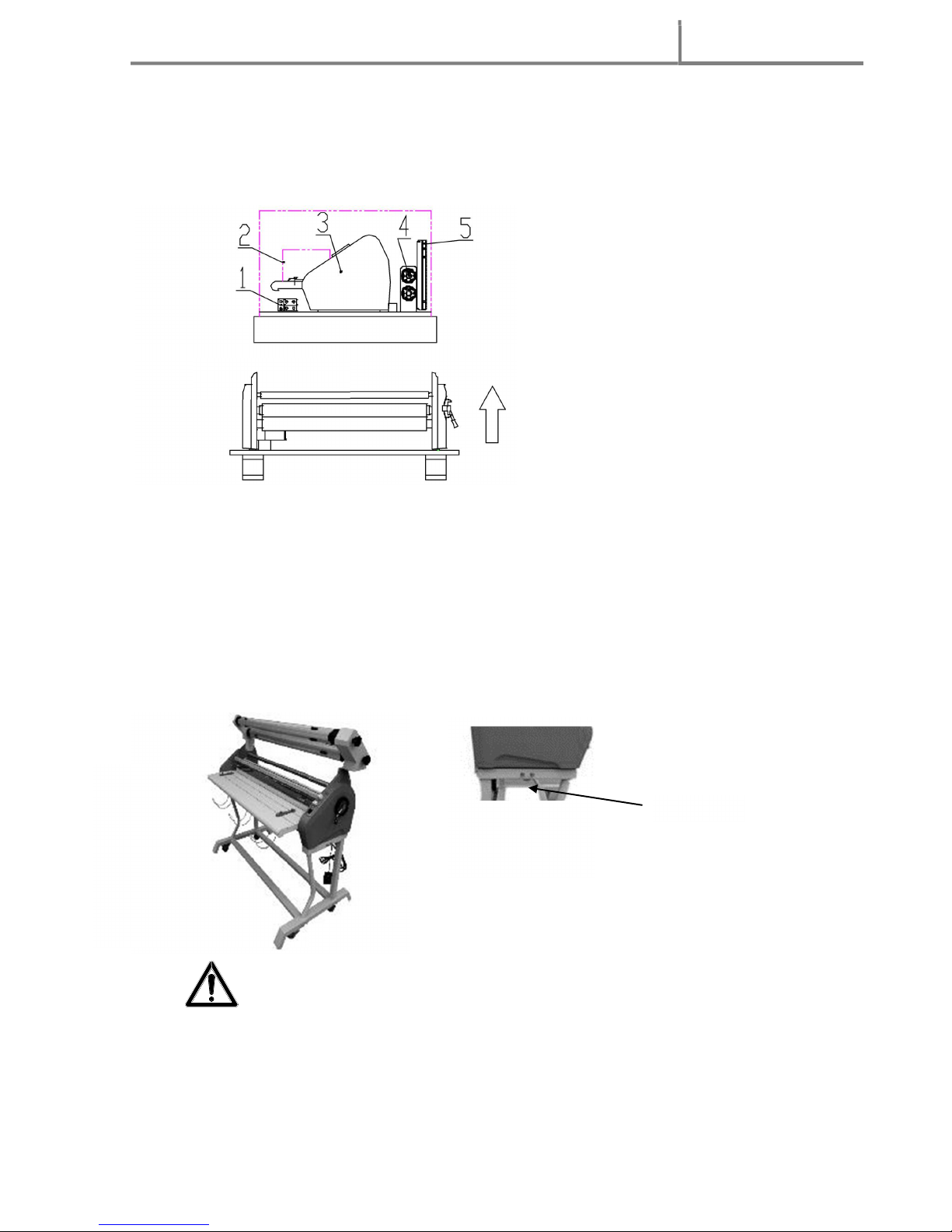
When the machine sits idle for an extended period of time, raise the top rubber roller
to avoid the distortion of the rubber surface.
Perform only the routine maintenance procedures referred to in these instructions
Do not leave excess adhesive build up on the rollers overnight

Gfp 44TH
October 2017
5
5. Operating Conditions
Place machine on level surface
Environment requirements:
Ambient temperature: 50⁰ F - 104⁰ F
Humidity:30%—80%;ideal humidity:55%
Due to the static on film rolls, you should try to keep the environment clean.
Provide enough space around machine to ensure the safe and effective operation. The
minimum area covered is 8 ft. x 10 ft.
Do not directly cut the films on the surfaces of the rubber rollers to avoid damages to the
rollers.
Do not put burrs, sharp knives or extra thick and hard materials in between the rollers.
Do not leave objects like tools, rulers, knives, etc. on the working panels or the side
cabinets to avoid their being rolled into the machine accidentally and damaging the
rollers.
For repairs and replacements, please contact your local distributor. unauthorized repairs
and dismantling will affect future maintenances of the machines.
The machine can laminate continuously objects up to 1/4” thick.
If this machine will not be used for a long period of time, please remove all films and gap the
rollers to prevent flat spots.
Warning: Do not keep the machines in direct sunshine or near it.
Do not keep the machine in dusty place or places with strong vibrations.

Gfp 44TH
October 2017
6
6. Packing List
Remove all parts from shipping create and boxes. Inspect parts and the machine
carefully. Any missing parts should be reported to the shipper upon receipt of
shipment.
NOTE: Refer to the System Components section for hardware locations
Machine Crate
Part Quantity
Part Quantity
Main Machine 1 Right rewind housing (#7) 1
Quick-Grip shafts 2 Locking Bolt 2
Stand locking screw 2 Feed Tray 1
Cardboard rewind tube 1 Allen wrench 8mm 1
Foot switch 1 Left rewind housing (#14) 1
Zippy knife 1 Hex screw 8mm x 80 12
Safety Shield 1 Flat washer 8 12
Rear Platform 1 Lock washer 8 12
Right stand side frame 1 Operating manual 1
Left stand side frame 1 Print hold down 1
Upper cross member 1 Print roll holder brackets 3
Lower cross members 2
Allen wrench 4mm (#7, #14) 1
Hex screw 5mm x 12
(#7, #14)
6
Flat washer 5 (#7, #12, #14) 10
Lock washer 5mm (#7,
#12, #14)
10
M5X10 (#12) 8
Phillips screwdriver
(#12)
1

Gfp 44TH
October 2017
7
7. Installation
7a. Uncrate the machine
1. Remove all the screws holding the crate to the base, lift and set to the side.
2. Remove all the screws holding the lid to the crate and remove the stand side frames
from the top of the crate.
3. Remove the cross members packed below the laminator feed tray.
7b. Assemble the stand
1. Assemble the stand as shown below.
Hint: The stand is easier to assemble upside down, then flip over when completed.
1. Fastening bolts 2. Side frames 3. Frame cross members
Upper cover
Side frames

Gfp 44TH
October 2017
8
7c. Remove the machine from base
1. Remove accessory boxes, shafts, and other components around the machine
2. Pull back plastic dust cover around the machine
7d. Bolt Machine to the Stand
1. Position the assembled stand close to the base and orient it to the machine. Stand
locking wheels are to the front of the machine.
2. Lift the machine and set it on the stand
3. Secure the machine to the stand using securing bolts in the accessory box.
Heavy! Handle with care!!
Warning: when moving the machine, lift by the machine side frames. Do not use
roller gap adjustment handle for lifting!
Locking bolt
1. Stand cross members
2. Rewind housing boxed
3. Machine
4. Unwind/rewind shafts
5. Rear platform assembly

Gfp 44TH
October 2017
9
7e. Attach rear platform
1. Secure the folding support of the rear platform to the rear of the machine by using bolts
in the accessory box
7f. Attach Upper Rewind supporting brackets
1. Use the Allen head screws to affix the rewind supporting plates to the machine side
frames
1. Left Rewind housing
2. Unwind shaft
3. Rewind shaft
4. Right rewind housing
5. Idler bar
5
Securing screws

Gfp 44TH
October 2017
10
7g. Attach upper shafts
1. Rotate the locking outer sleeves in the direction of the arrow indicated in Figure 1,
to their open position aligned with the inner sleeve as in Figure 2.
2. Insert slotted end of each upper shaft into the right shaft housing with tension adjustment
knobs and drop shaft into place as in Figure 3.
3. Rotate all outer locking sleeves to lock shafts in place
4. A cardboard core is used on upper rewind shaft to take up film liner as in Figure 4
Figure 1 Figure 2
Figure 3 Figure 4
Locking Outer
Sleeve
Locking Inner
Sleeve
Shaft slot
Cardboard rewind tube

Gfp 44TH
October 2017
11
7h. Attach Safety Shield
1. Hold the handles at both ends of the safety shield and align mounting block on safety
shield with spring loaded pin in left side frame. Move shield in the direction of the arrow
below
2. Align right mounting block on safety shield with locating pin on right side frame
3. The safety shield may be rotated up for access to the rollers.
7i. Attach Print Hold Down Clamp
1. Rotate the safety shield up and unscrew the thumbscrews at the both ends of the feed
table. Then insert the print hold down clamp under each thumbscrew and tighten. To
remove, rotate the safety shield up and unscrew the thumbscrews at the both ends of
the feed table, and remove the print hold down clamp, then tighten the thumbscrews.
Thumbscrew

Gfp 44TH
October 2017
12
8. System Components
1. Left Side Cover
2. Feed tray
3. Print roll hangers
4. Stand
5. Roller gap handle
6. Right side cover
7. Rewind housing
8. Idler bar
9. Safety shield
10. Rear exit panel
11. Rear Platform
12. Support hinges
13. Emergency stop switch
14. Left rewind housing
15. Quick -grip unwind shaft
16. Quick-grip rewind shaft

Gfp 44TH
October 2017
13
9. Control Panel
1. When illuminated, indicates that the machine is turned on.
2. The temperature adjustment knob is used to adjust temperature of upper roller. When
turned all the way counterclockwise the heat is off. Rotating it clockwise will adjust
the temperature of the roller. Maximum temperature is 302° F.
3. Speed knob is used to adjust speed of the roller.
4. The forward, stop, and reverse switch is used to stop rotation of the roller and switch
rotation direction of the rollers
5. The green LED Ready light will illuminate when the upper roller gets to the set
temperature.
6. Temperature display screen is used to display actual temperature of the upper roller.
Note: The machine does not have continuous reverse. The reverse function can only be
utilized with the foot switch.
1.
Power indicator 4. Motor function switch
2. Temperature adjustment knob 5 Ready light
3. Speed adjustment knob 6. Temperature display screen
Note: Reserve operation can only be utilized with the foot switch
.
1
2
3
4
5
6

Gfp 44TH
October 2017
14
10. Roller Gap Adjustment
1. The roller gap adjustment handle (see Fig.) is located on the right-side cover of the
laminator and is used to adjust the roller gap and pressure.
2. There are four mounting gap settings; 1/4” (6mm), 3/16” (5mm),1/8” (3mm)and
1/16” (1.5mm). Zero is for full pressure when laminating.
Caution! When not in use, set the Gap handle to the fully open position. When warming
up the machine, set the Gap handle to ZERO and turn the motor speed to 1/2.
11. Operation
1.
Connect the attachment plug provided with the laminator to a suitably grounded outlet
only. This machine must have reliable earth wire to ensure the safety of the machine
during operation.
2. Contact an electrician should the attachment plug provided with the laminator not
match the receptacles at your location.
3. Ensure that the voltages of the power supply you are using match the rated working
voltages before operations. Do not use incorrect power supply.
4. Make sure the Motor function switch on the front control panel is in the center, stop
position.
5. Connect the power cord to the wall outlet and turn on the power switch to ON as
shown in the figure below. You should hear three audible beeps, this means the
machine is in the operation mode. If you only hear two beeps, check the Motor
function switch for the proper location.

Gfp 44TH
October 2017
15
12. Loading top supply roll
1. Slide the top supply roll onto the rear Supply unwind shaft
a. If using Liner-in film, the web should come off the bottom of the roll, for Liner-out
film the web should come off the top of the roll
2. Position the roll in the middle of the supply shaft.
3. Adjust the brake tension by turning the Tension adjustment knob
(Note: the brake tension should not prevent roll from turning)
4. Slide empty cardboard tube onto the top, front Liner rewind shaft
13. Threading film
1. Turn the Roller Gap adjustment handle to full open position to lift the upper rubber roller.
2. Pass the film web under the idler bar and down in front of the roller
3. Separate 1” of the paper liner from the film web and attach film web to a leader
board the width of the film roll then insert leader board into the rollers
4. Lower the top rubber roller onto the leader board
5. Pull the liner up and attach to a cardboard tube on the liner rewind shaft as in the diagram
below
6. Use foot pedal to advance the film web until the leader board is under the roller
Note: The film should be wrinkleless and tight to the surface of the roller. If the
film is not tight enough, increase the roller pressure. If wrinkles appear in the
film web, adjust the brake tension on the top film supply roll.
1. Feed tray 5. PSA Film
2. Print 6. Idler roller
3. Top roller 7. Rear platform
4. Release Liner 8. Rolled graphics

Gfp 44TH
October 2017
16
14. Adjusting Brake Tension
1. Adjust the brake tension so the film does not wind up on the rewind and the release liner does
not get pulled into the rollers.
2. The release liner should have a small amount of sag as it releases from the overlaminate but not
so much that it will be pulled into the nip area of the rollers.
1. Brake pressure adjusting knob; 2. Rewind/unwind locking sleeve; 3. Rewinding shaft; 4. Unwind shaft; 5.
Roll film; 6. Rewind tube
15. Laminating Cold PSA film
Note: It is hard to remove film adhesive once it gets onto the rubber rollers.
When laminating, always use film rolls the same width as the materials. If your
sheets are narrower than the film roll, use a laminating sled to keep the film
adhesive from sticking to the bottom rubber roller of the machine. Always use a
media roll the same width or wider than the film supply roll.
To clean the rollers, use rubber eraser or Isopropyl Alcohol and a lint free cloth.
15a. Single sheets or media from a roll
1. Load a roll of laminating film on the top roller (see Loading top Roll supply section 12)
2. Turn the Roller Gap adjustment handle to full open position to lift the upper rubber roller.
3. Pass the film web under the idler bar and down in front of the roller
4. Separate 1” of the paper liner from the film web and attach film web to a leader
board the width of the film roll, then insert leader board into the rollers
5. Lower the top rubber roller onto the leader board
6. Pull the liner up and attach to a cardboard tube on the liner rewind shaft
7. Use foot pedal to advance the film web until the leader board is under the roller
8. Pull the bottom media web up or slide single sheet to adhere to the exposed film web
9. Use foot pedal to advance both webs until cleared of the nip rollers
10. Lower the Gap adjustment handle to a gap position suitable for your image

Gfp 44TH
October 2017
17
15b. Single sheets using a sled
1. Load a roll of laminating film on the top roller (see Loading top Roll supply section 12)
2. Turn the roller gap handle to lift the upper roller.
3. Select a piece of Gatorboard or other PVC mounting board the width of the film
web to use as a sled under the print to be laminated
4. Insert the sled between the nip rollers and lower the top roller until it touches the sled
5. Reverse the motor to back the sled out of the rollers
6. Pass the film web under the idler bar and down in front of the roller
7. Separate 1” of the paper liner from the film web, attach film web to a leader board
the width of the film roll and insert leader board into the rollers
8. Use foot pedal to advance the film web half way through the roller and stop
9. Position print on the sled and insert into rollers
10. Depress the foot switch and run sled through
11. Insert another leader board or next sled right behind the first sled
16. Laminating and Mounting in one pass
16a. Heat-activated pouch boards
1. The recommended temperature setting is 10 on Temp dial
2. The recommended speed setting is 1/2
Note: If the board comes out cloudy, reduce the speed and run the board back through
the machine.
3. Remove the print hold down clamp.
4. When the READY light illuminates, you are ready to run the boards.
5. Place the print to be laminated under the film layer on the adhesive side of the board
then bring the film layer down over the print
6. Set the roller gap handle to the correct setting for the board thickness
7. Insert the board, sealed edge first, into the rollers and press FWD or use the foot pedal

Gfp 44TH
October 2017
18
16b. Thermal film and thermal boards
1. Load a roll of laminating film on the top roller (see Loading Top Roll supply section 12)
2. The recommended temperature setting is 10 on Temp dial (302° F)
3. The recommended speed setting is 1/2
Note: If the board comes out cloudy, reduce the speed and run the board back
through the machine.
4. Remove the print hold down clamp
5. When the READY light illuminates, you are ready to run the boards.
6. Place the print to be laminated on the adhesive side of the board Set the roller gap
handle to the correct setting for the board thickness
7. Insert the board into the rollers and press FWD or use the foot pedal
8. Insert another leader board or next board right behind the first board to keep the film
adhesive from touching the bottom roller
17. Laminating pouches
1. The recommended temperature setting is 10 on Temp dial (302° F)
2. The recommended speed setting is 1
Note: If the pouch comes out cloudy, reduce the speed and run the board back
through the machine.
3. When the READY light illuminates, you are ready to run the boards.
4. Insert the material to be laminated into the pouch ensuring there is a boarder of film all
the way around the print.
6. Place the pouch with the print into a carrier provided by the pouch manufacturer.
7. Smooth out any wrinkles with side of your hands or soft scraper.
8. Adjust the roller gap adjustment handle to the 1/16” setting.
9. If the print comes out cloudy or has air bubbles, lower the pressure setting to ‘0’ and
run back through the rollers.
NOTE: Always run a test sheet similar to the finished product to ensure you have the
proper settings before the actual job is run.

Gfp 44TH
October 2017
19
18. Mounting
18a. Mounting Adhesive back vinyl to boards
1. Load a roll of printed adhesive back vinyl on the top supply roller (see Loading top Roll
supply section 12)
2. Turn the roller gap handle to lift the upper roller.
3. Select a piece of Gatorboard or other PVC mounting board the width of the vinyl web
and the same thickness as the board to be coated for use as a leader board
4. Insert the leader board between the nip rollers
5. Lower the top roller onto the leader board to the preset gap setting on the gap
adjustment handle
6. Pass the vinyl web under the idler bar and down in front of the roller
7. Separate 1” of the paper liner from the vinyl web, attach vinyl web to a leader board
8. Use foot pedal to advance the leader board half way through the roller and stop
9. Insert mounting board to be coated and depress foot switch
10. After the last board, insert leader board to keep adhesive from contacting the rollers
18b. Pre-coating mounting boards
1. Load a roll of mounting adhesive on the top roller
2. Insert leader board the same thickness as the board to be coated and the width of
the mounting adhesive, between the nip rollers and lower the top roller to the
preset gap setting on the gap adjustment handle
3. Pull mounting adhesive down over the idler bar and over the front of nip roller
and adhere to the leader board
4. Run leader board half way through the roller and stop
5. Insert mounting board to be coated and depress foot switch
6. After the last board, insert leader board to keep adhesive from contacting the
rollers
Other manuals for 44TH
1
Table of contents
Other Gfp Laminator manuals