Gfp 455 TH User manual

Gfp
400 Series
January 2011
1
OPERATING MANUAL Gfp 455 TH
Gfp 463 TH
Please read this manual carefully before operating!

Gfp
400 Series
January 2011
2
Table of Contents
Contents Pa e
1. Introduction …………………………………………………… 3
2. Important Safety Instructions………………………………….. 3
3. Installation Safe uards ……………………………………….. 4
4. General Safe uards……………………………………………. 5
5. Operatin Conditions …………………………………………. 6
6. System Components ………………………………………….. 7
7. Control Panel …………………………………………………. 8
8. Packin List ………………………………………………… .. 9
9. Installation
A. Uncrate the machine……………………………………. 10
B. Remove heat tube packa e……………………………... 10
C. Remove machine from Skid……………………………. 11
D. Assemble machine stand……………………………….. 12
E. Set Machine on stand…………………………………... 13
F. Attach supply support brackets………………………… 14
10. Installin heat tube
A. Insert heat tube…. .…………………………………….. 15
B. Connect electric wires..………………………………… 16
11. Installin Take up Reel ……………………………………….. 17
12. Additional installation items …………………………………. 18
13. Removin Press roller assembly……………………………… 18
14. Loadin film ………………………………………………….. 19
15. Threadin Film ……………………………………………….. 20
16. Operation ……………………………………………………... 21
17. Roller Gap………….. ………………………………………… 21
18. Roller Gap adjustment…………………………………………. 22
19. Optional Rewind ……………………………………………… 23
20. Troubleshootin ………………………………………………. 24
21. Specifications …………………………………………………. 25
22. Warranty ………………………………………………………. 26

Gfp
400 Series
January 2011
3
1. Introduction
Thank you for choosin a Gfp laminator. It has been desi ned and manufactured to
provide years of continuous service. Please read this manual thorou hly before
operatin . Please inspect the box and the laminator for shippin dama e. Dama e
should be brou ht to the attention of the deliverin carrier immediately. For a list of
shippin components see “Packin List” on pa e 9.
2. Important Safety Instructions
In this operatin manual you will find important safety messa es re ardin the product.
Read these instructions carefully, failure to comply with the followin safety procedures
could result in serious injury.
WARI Do not attempt to service or repair the laminator. Only authorized
maintenance and service technicians should make repairs.
WARI Do not connect the laminator to an electrical supply or attempt to
operate the laminator until you have completely read these instructions.
Maintain these instructions in a convenient location for future reference.
WARI To uard a ainst injury, the followin safety precautions must be
observed in the installation and use of the laminator

Gfp
400 Series
January 2011
4
3.
Installation Safeguards
• Shippin dama e should be brou ht to the immediate attention of the
deliverin carrier
• Avoid locatin the laminator near sources of heat or cold. Avoid locatin
the laminator in the direct path of forced, heated or cooled air
• The receptacle must be located near the equipment and easily accessible.
• Connect the attachment plu provided with the laminator to a
suitably rounded outlet only. This machine must have reliable earth wire
to ensure the safety of the machine durin operations
• Contact an electrician should the attachment plu provided with the
laminator not match the receptacles at your location
• Ensure that the volta es of the power supply you are usin match the rated
workin volta es before operations. Do not use incorrect power supply
• Do not use dama ed wires or sockets. If abnormal conditions occur, switch
off the power supply first.
• Only a licensed electrician should install wirin and outlet for the
laminator
• Do not defeat or remove electrical and mechanical safety equipment such as
interlocks, shields and uards

Gfp
400 Series
January 2011
5
4. eneral Safeguards
• Keep hands, lon hair, loose clothin , and articles such as neckties away from
rollers to avoid entan lement and entrapment. The rollers have pinch points that
can trap body parts or clothin and cause serious injury
• Do not use the machines for purposes other than lamination and mountin ,
otherwise dama es to the machine or accidents may occur
• Keep out of reach of children
• Keep flammable and wet objects away from the machine.
• Do not use flammable sprays or materials when cleanin the machine
• Do not leave the machine unattended durin operations.
• Do not mount metal materials or other hard objects.
• Do not put burrs, sharp blade or ri id materials in between the two rubber rollers.
• Do not attempt to laminate items that exceed total recommended material thickness
of the unit.
• Do not touch the rollers when they are hot or place forei n object inside the
machine.
• Do not cut adhesive films directly on the surface of the rollers to avoid dama in
the rubber coatin .
• Shut down the machine after laminatin to avoid misusin this machine by others.
• Shut down the power before movin the machine
• Note the locations of foot wheels while movin or operatin this machine to avoid
injuries to your feet.
• Disconnect from the power supply before repair or maintenance.
• Disconnect from the power supply when the machine is not in use for a
lon time.
• When the machine lies idle for a lon period of time, raise the top rubber roller to
avoid the distortion of the rubber surface.
• Do not cover the surface of the machine until the machine has completely cooled.
• Perform only the routine maintenance procedures referred to in these instructions

Gfp
400 Series
January 2011
6
5. Operating Conditions
Place machine on level surface
Environment requirements:
Ambient temperature: 50⁰ F - 104⁰ F
Humidity:30%—80%;ideal humidity:55%
Due to the static on film rolls, you should try to keep the environment clean.
Provide enou h space around machine to ensure the safe and effective operation.
The minimum area covered is 8 ft. x 10 ft.
Do not directly cut the films on the surfaces of the rubber rollers to avoid dama es to
the rollers.
Do not put burrs, sharp knives or extra thick and hard materials in between the
rollers. Do not leave objects like tools, rulers, knives, etc on the workin panels or the
side cabinets to avoid their bein rolled into the machine accidentally and dama in
the rollers.
For repairs and replacements, please contact your local distributor. Unauthorized
repairs and dismantlin will affect future maintenances of the machines.
The machine can laminate continuously objects less than ½” thick.
For objects over ½” but less than 1” thick, use the pedal switch.
Warning: Do not keep the machines in direct sunshine or near it.
Do not keep the machine in dusty place or places with strong vibrations.
Gfp
400 Series
January 2011
7
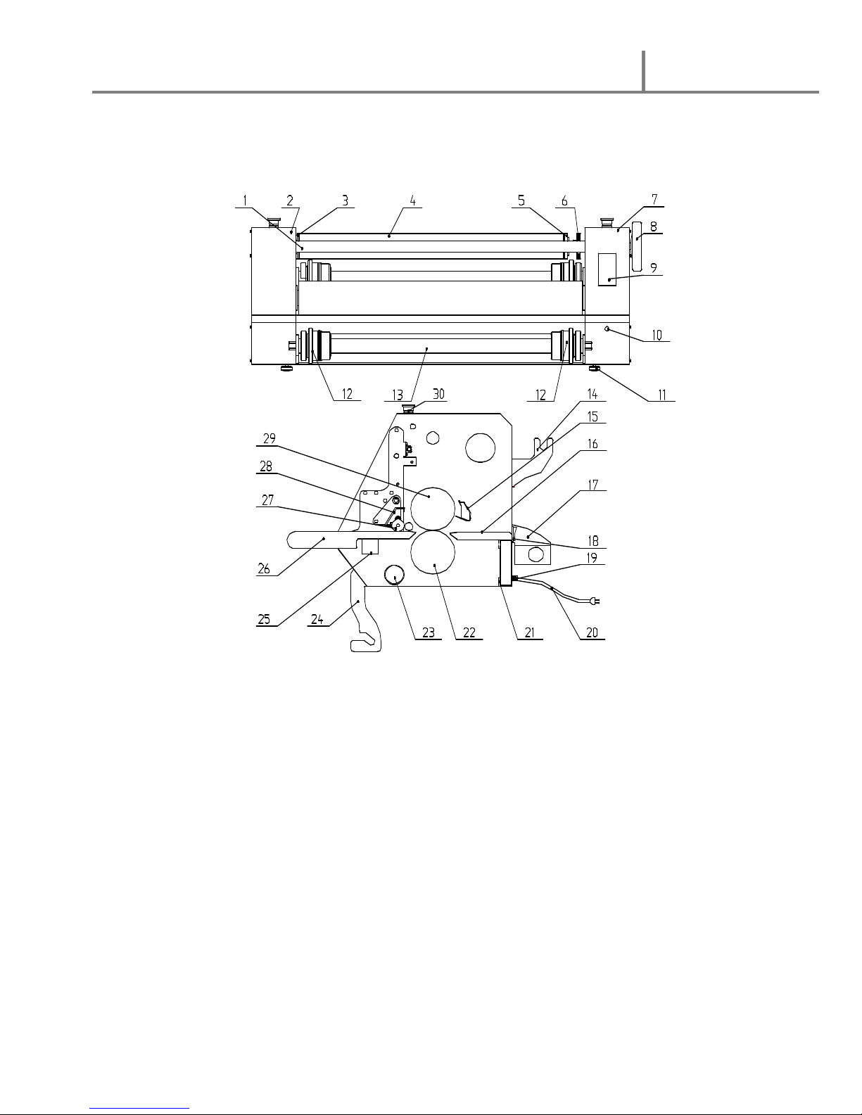
6. System Components
1.
Linka e Axle 16. Exit table
2. Left cabinet 17. Rear rewind assembly
3. Rewind tube axle 18. Main power switch
4. Backin paper rewind tube 19. Fuse
5. Rewind tube positionin sleeve 20. Power cord
6. Brake adjustment wheel 21. Real panel
7. Ri ht cabinet 22. Bottom nip roller
8. Roller Gap adjustment hand-wheel 23. Support crossbar
9. Control panel 24. Bottom supply mandrel bracket
10. Foot pedal plu connection 25. Cross member
11. Levelin foot 26. In-feed table
12. Film Core adaptor/brake 27. Pressin roller
13. Bottom supply mandrel 28. Nip roller safety shield
14. Top supply mandrel bracket 29. Top heat roller
15. Temperature sensor 30. Emer ency stop switch

Gfp
400 Series
January 2011
8
7. Control Panel
1. Cold laminatin indicator 6. Hot / Cold heater switch
2. Hot laminatin indicator 7. Forward / Reverse switch
3. Ready li ht indicator 8. Continuous/ foot pedal operation
4. Temperature display screen 9. Temperature adjustment
5. Speed adjustment
Note:
1. The machine does not have continuous reverse. Reverse can only operate usin the pedal switch
2. If the photo-electric eye stops the machine, move operation switch to “Step” then back to
C
“continuous” operation.
2
3
4
5
6
7
1
9
8
Gfp
400 Series
January 2011
9
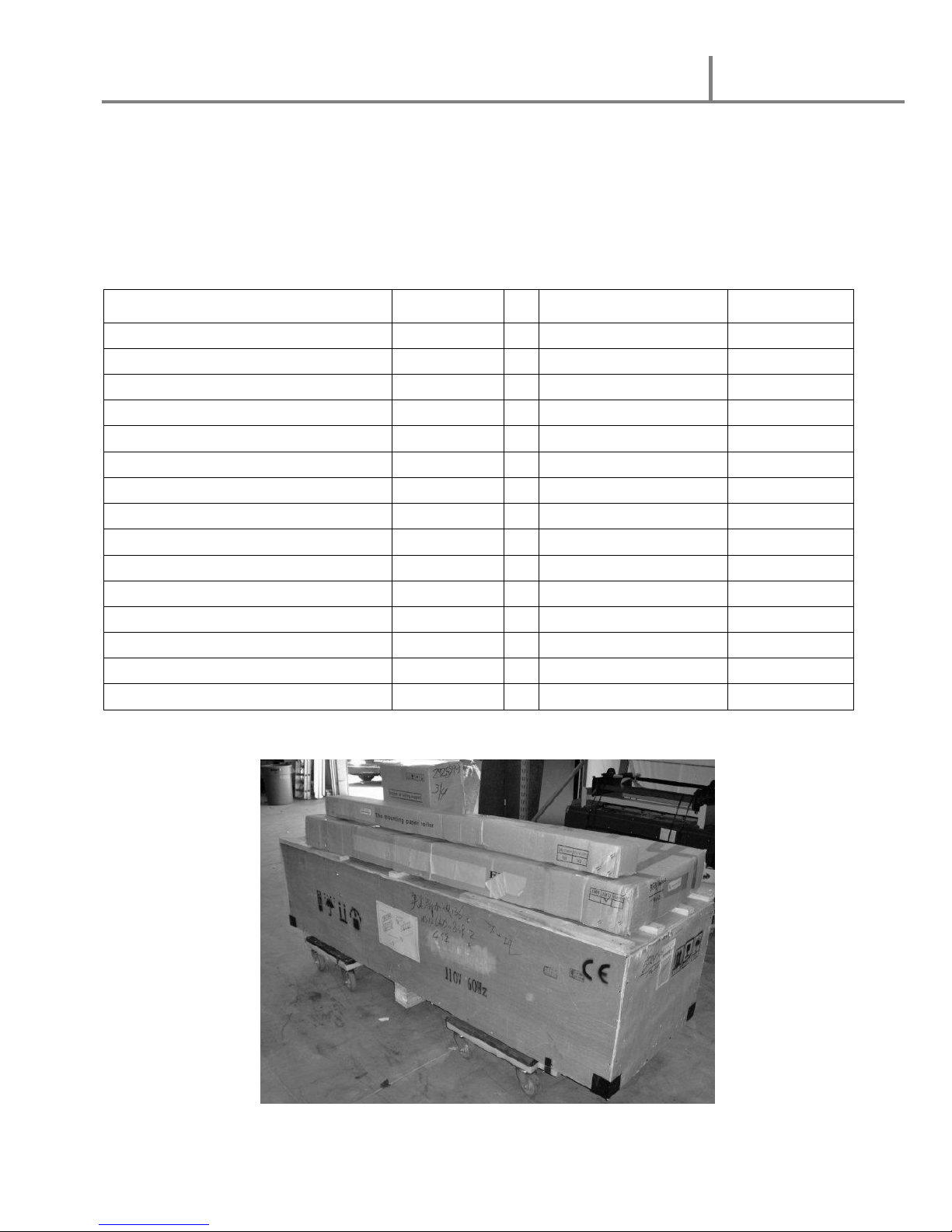
8. Packing List
Remove all parts from shippin create and boxes. Inspect parts and the machine
carefully. Any missin parts should be reported to the shipper upon receipt of shipment.
Main Machine Crate Stand Box
Part Quantity Part Quantity
Main Machine 1 Cross beams 2
Supply Mandel 2 Middle beam 1
Rewind tube 1 Left side stand 1
Supply Mandel brackets 4 Ri ht side stand 1
Foot Pedal 1 Allen key 1
Heat tube 1 8 x100 hex screw 8
Hex Screw 16 8 x 60 hex screw 4
Sprin Spacer 16 #8 flat washer 12
Flat washer 16 #8 lockin washer 12
Levelin Feet 4
Stand anchor bolts 4
Allen wrench 5mm 1
Film cutter 1
Operation manual 1
Gfp
400 Series
January 2011
10
9. Installation
A. Uncrate the machine
1. Remove screws around the base of the crate includin corner supports
2. Lift crate strai ht up and off the skid
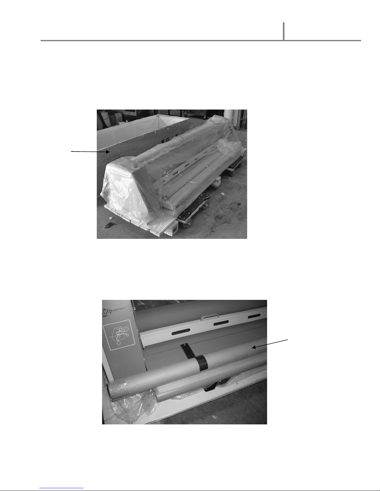
B. Remove Heat tube package
1. Remove nuts on heater support brackets that hold the cardboard tube to
the feed table and remove the heater packa e
2. Bolts in the feed table are used for the paper side uides
Heat tube
packa e
Crate
Other manuals for 455 TH
1
This manual suits for next models
1
Table of contents
Other Gfp Laminator manuals


