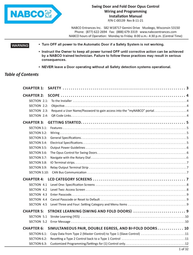
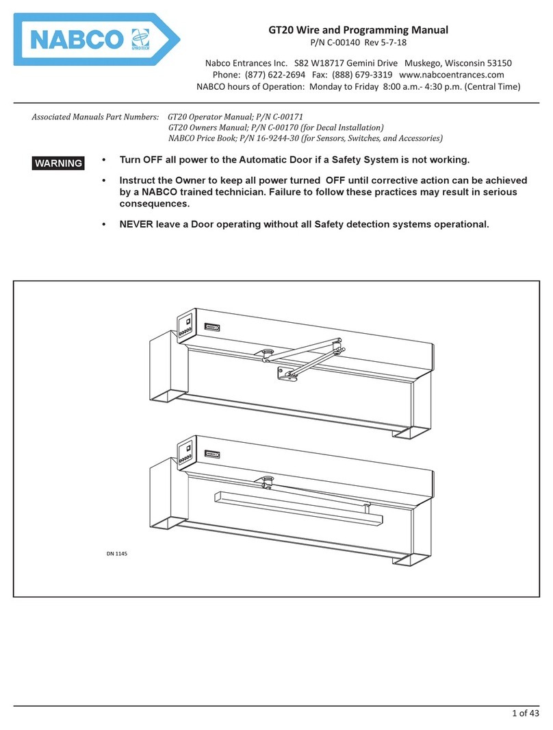
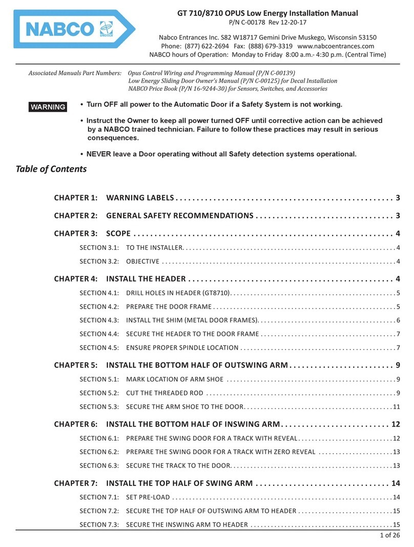
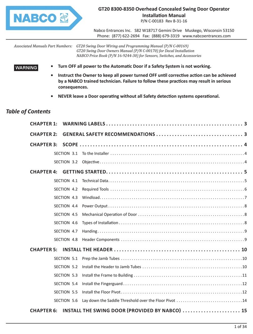
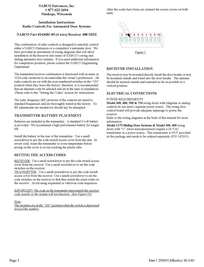
Nabco GT 300 User manual

1 of 38
Opus Overhead Concealed Swing Door GT 300-350-8300-8350
Installaon Manual
P/N C-00175 Rev 5-23-18
Nabco Entrances Inc. S82 W18717 Gemini Drive Muskego, Wisconsin 53150
Phone: (877) 622-2694 Fax: (888) 679-3319 www.nabcoentrances.com
NABCO hours of Operaon: Monday to Friday 8:00 a.m.- 4:30 p.m. (Central Time)
Associated Manuals Part Numbers: Opus Control Wiring and Programming Manual; P/N C-00139
Swing Door Owners Manual; P/N C-00110 (for Decal Installation)
NABCO Price Book; P/N 16-9244-30 (for Sensors, Switches, and Accessories)
• Turn OFF all power to the Automatic Door if a Safety System is not working.
• Instruct the Owner to keep all power turned OFF until corrective action can be achieved
by a NABCO trained technician. Failure to follow these practices may result in serious
consequences.
• NEVER leave a Door operating without all Safety detection systems operational.
WARNING
GT 8300
GT 8350
GT 300
GT 350
DN 0376

2 of 38
GT 300-350-8300-8350 Opus Overhead Concealed Swing Door Installaon Manual www.NabcoEntrances.com
P/N C-00175 Rev 5-23-18
Table of Contents
4
4
5
5
5
5
5
6
6
6
6
6
7
8
8
9
9
10
11
11
11
12
13
13
16
17
18

3 of 38
www.NabcoEntrances.com GT300-350-8300-8350OpusOverheadConcealedSwingDoorInstallaonManual
Rev 5-23-18 P/N C-00175
21
22
22
23
25
25
26
26

GT 300-350-8300-8350 Opus Overhead Concealed Swing Door Installaon Manual www.NabcoEntrances.com
P/N C-00175 Rev 5-23-18
Warning labels are universal and used to alert an individual of potential harm to one’s self or to others. The following warning labels are
listed in a hierarchy order that denes the most potential danger rst, and the least potential danger last. Please refer to this page in the
event that a warning label is displayed within this manual and further denition needs to be explained.
Indicates potentially dangerous situations. Danger is used when there is a hazardous
situation where there is a high probability of severe injury or death. It should not be
considered for property damage unless personal injury risk is present.
Indicates a hazardous situation which has some probability of severe injury. It should not be
considered for property damage unless personal injury risk is present.
Indicates a hazardous situation which may result in a minor injury. Caution should not be
used when there is a possibility of serious injury. Caution should not be considered for
property damage accidents unless a personal injury risk is present.
Notice: Indicates a statement of company policy as the message relates to the personal safety or protection
of property. Notice should not be used when there is a hazardous situation or personal risk.
Note: Indicates important informaon that provides further instrucon.
Do not install, operate or service this product unless you have read and understand the
General Safety Recommendations, Warning Labels, contained in this manual. Failure to do
so may result in bodily injury, or property damage.
Read, study and understand the installation and operating instructions contained in, or
referenced in this manual before operating. If you do not understand the instruction, ask a
qualied technician. Failure to do so may result in bodily injury, or property damage and will
nullify all warranties.
Disconnect all power to the junction box prior to making any electrical connections. Failure
to do so may result in seriouc personal or fatal injury. When uncertain whether power supply
is disconnected, always verify using a voltmeter.
Do not place nger or uninsulated tools inside the electrical controller. Touching wires or
other parts inside the enclosure may cause electrical shock, serious injury or death.
The Ground wire from the Opus Control 120 VAC Harness, and the Incoming 120 VAC
Ground wire must be connected to the Ground screw located within the Swing door Header.
If the door appears broken or does not seem to work correctly, it should be immediately
removed from service until repairs can be carried out or a qualied service technician is
contacted for corrective action.
Notice: This manual, the owner’s manual and all other associated manuals must be given to and retained
by the purchasing facility or end user.
Notice: Wiring must meet all local, state, federal or other governing agency codes.
Notice: All electrical troublshooting or service must be performed by qualied
electrical technicians and must comply with all applicable governing
agency codes.
DANGER
WARNING
CAUTION
WARNINGWARNINGWARNING
WARNING
DANGER
DANGER
CAUTION
CAUTION

5 of 38
www.NabcoEntrances.com GT300-350-8300-8350OpusOverheadConcealedSwingDoorInstallaonManual
Rev 5-23-18 P/N C-00175
A pedestrian Door that does not have Its glass sections installed at the Factory
shall specify that the glazing material employed is to comply with the requirement in UL
325 par.29.5.1:
Base Model OHC Bottom Load OHC Side Load
GT300 GT8300
GT350 GT8350
SIDE LOAD
HEADER
Access Cover
Swing Arm
5.50”
6.00”
1.00”
DN 0530
BOTTOM LOAD
HEADER
Access Cover
Swing Arm
5.50”
5.00”
1.00”
CAUTION

6 of 38
GT 300-350-8300-8350 Opus Overhead Concealed Swing Door Installaon Manual www.NabcoEntrances.com
P/N C-00175 Rev 5-23-18
XUtilize Sensor(s) to open a Swing door.
• Sensors activate the Control by detecting motion of pedestrians (or moving objects) that come into range.
X
XUtilize a Knowing Act to open a Swing door.
• A conscious effort that is carried out in many different ways, including (but not limited to): manually opening/
X
Specification Measurement
Bottom Load Side Load
6-1/8” (156 mm) 7-18” (181 mm)
DN0461
Inswing
Single
Right Hand
Inswing
Single
Le Hand
IN
OUT
IN
OUT
IN
OUT
IN
OUT
IN
OUT
IN
OUT
IN
OUT
IN
OUT
Simultaneous
Outswing Pair
Simultaneous
Inswing Pair
Outswing
Single
Right Hand
Outswing
Single
Le Hand
Dual Inswing
Outswing Pair
Dual Inswing
Outswing Pair

7 of 38
www.NabcoEntrances.com GT300-350-8300-8350OpusOverheadConcealedSwingDoorInstallaonManual
Rev 5-23-18 P/N C-00175
DN 0463
Base Plate Front Side of Header
#10-24 x 3/4”
Phillips Head Screw
Snap In Dress Channel
Dress Plate
Boom Lock Cover Plate
Snap In Channel Pivot
(Finger Guard or No Finger Guard)
Figure 1 Open Bottom Load Header
XDuring Automatic Operation: the Inswing door opens to the Interior side of the building/room. The Panic Latch is
then used as a Door Stop.
XDuring Emergency Operation: the Inswing door is manually pushed Out to the exterior side of the building/
immediately shuts the Swing door OFF.
Figure 2 Panic Latch during Automatic Operation (Panic Latch acts as Door Stop)
DN 0466
Panic Latch
(In Automac Posion)
EXTERIORINTERIOR
INSWING
DN 0316
EXT
Back of Panic Latch
(EXT→ must point to
Exterior side of Building)
Panic
Latch
Screws
Washers
Strike Side
of Header
Figure 3 Install the Panic Latch

8 of 38
GT 300-350-8300-8350 Opus Overhead Concealed Swing Door Installaon Manual www.NabcoEntrances.com
P/N C-00175 Rev 5-23-18
DN 0487
Insert Wires and Spring Coil
Figure 4
X
X
DN 0465
Screws
Door Stop
(Outswing Confi gura on)
Washers
Door Stop
(Inswing Confi gura on)
Strike Side
(of Header)
Figure 5 Install the Door Stop
Figure 6 Adhere Jamb Drilling Template
DN 0469
Line marking
Center of Jamb Tube
Jamb Drilling Template

9 of 38
www.NabcoEntrances.com GT300-350-8300-8350OpusOverheadConcealedSwingDoorInstallaonManual
Rev 5-23-18 P/N C-00175
X
X
Figure 7 Layout Header and Jamb Tubes
DN 0468
Top of Header
Rough
Opening Interior Side of Building
Jamb Tube
ON
Figure 8 Secure Bottom Load Header to Jamb Tubes
DN 0448
Jamb Tube
Header
Note: Incoming 120 VAC Power wires must be pulled through the Strike end of Header for a single Swing door or the middle of
Header for a simultaneous pair Swing door. It is recommended to install wires into an Electrical conduit.
Figure 9
1/4” Shim and plumb
for proper clearance
DN 0758
Jamb Tube
Horizontal
Transom
1/4” Shim and plumb
for proper clearance

10 of 38
GT 300-350-8300-8350 Opus Overhead Concealed Swing Door Installaon Manual www.NabcoEntrances.com
P/N C-00175 Rev 5-23-18
Figure 10 Anchor Placement
36” max
48” max
48” max
Y Y Y
Y YY
Note: It is recommended to countersink holes as required to ush the surface.
Note: It is recommended to drill tap threads for anchors in a steel or aluminum structure.
Figure 11 Screw Anchors
DN 0658
1/4” Fasteners
1/4” Anchor Hole(s)
Note: Screws must be appropriate for the type of structure being fastened into. Screws are not provided by NABCO.
Note: Do not overghten screws to prevent deforming Weatherstrip Extrusion. Ensure each screw is ush to the Jamb tube.
Figure 12 Install Weather Strip onto Finger Guard Mounting Plate
DN 0470
Weather Strip
Channels
Weather Strip
Channels
Finger Guard Mounng Plate
SIDE VIEW Assembled Finger Guard

11 of 38
www.NabcoEntrances.com GT300-350-8300-8350OpusOverheadConcealedSwingDoorInstallaonManual
Rev 5-23-18 P/N C-00175
Figure 13 Secure Weatherstrip Extrusion to Hinge Jamb Tube
DN 0471
Hinge Jamb Tube
Weatherstrip Extrusion
Center Line
Plumb Line
1/8” Screw Hole
1/8 x 1” Self Tapping
Steel or Zinc Plated Screw
Note: Locaon of Contents within Header are subject to change according to Swing door specicaons.
DN 0462 ①
②③④
⑤
⑥
ON
SIGNAL
INPUT
MOTOR
J5
LESS
SENSITIVE
R28
CURRENT LIMIT
LED
SW2
SW1
CLOSELCHKTDPGTDASBCHKOPENSTOP
R2 R3 R4 R5 R6 R7 R8
MAGNUM IV
TRANSFORME R
FUSE1:3A 120/240
AUX
PWR
FUSE 2; 0.5 A 24 VAC
Figure 14 Contents of Header
DN 0472
Route wires through white plasc Wire Clip
White plasc Wire Clip
Figure 15
Note: If 120 VAC Power wires must be installed from Hinge Side of Header, ensure that wires are securely clipped, to prevent
pinching of the wires during the Motor/Operator installaon process.

12 of 38
GT 300-350-8300-8350 Opus Overhead Concealed Swing Door Installaon Manual www.NabcoEntrances.com
P/N C-00175 Rev 5-23-18
DN 0464
Motor/Operator
Rear Mount Bracket
Washer
Hex Jam Nut
Motor/Operator
Mount
Figure 16
Figure 17 Mount Motor/Operator into Header
DN 1058
Pivot Base TabsMotor Operator Mount
Motor/Operator
ENTRANCESINC.
R3J724456
NABCO
Tabs on Brackets
Switch Harness
Note: It may be necessary to mount a So Starter Capacitor on the Operator prior to installing the Analog Control. For detailed
informaon, please refer to the “Analog Control Wiring and Adjustment Manual; P/N 15-10745”.
Figure 18
DN 1525
Insert Opus/bracket with bracket being
parallel to the header.
Boom of Header (w/Access Cover)
Rotate Opus/bracket so that Opus is parallel
to the header. Then ghten capscrews. To p of Header
Channel
10-24x.875" Socket Head Cap screws
Opus Control
Rotate Mounng Bracket

13 of 38
www.NabcoEntrances.com GT300-350-8300-8350OpusOverheadConcealedSwingDoorInstallaonManual
Rev 5-23-18 P/N C-00175
Figure 19 Adhere Jamb Drilling Template
DN 0469
Line marking
Center of Jamb Tube
Jamb Drilling Template
X
X
Figure 20 Layout Header and Jamb Tubes
DN 0468
Top of Header
Rough
Opening Interior Side of Building
Jamb Tube
ON
Figure 21 Secure Bottom Load Header to Jamb Tubes
DN 0448
Jamb Tube
Header

GT 300-350-8300-8350 Opus Overhead Concealed Swing Door Installaon Manual www.NabcoEntrances.com
P/N C-00175 Rev 5-23-18
Note: Incoming 120 VAC Power wires must be pulled through the Strike end of Header for a single Swing door or the middle of
Header for a simultaneous pair Swing door. It is recommended to install wires into an Electrical conduit.
Figure 22
1/4” Shim and plumb
for proper clearance
DN 0758
Jamb Tube
Horizontal
Transom
1/4” Shim and plumb
for proper clearance
Note: It is recommended to countersink holes as required to ush the surface.
Note: It is recommended to drill tap threads for anchors in a steel or aluminum structure.
Figure 23 Anchor Placement
36” max
48” max
48” max
Y Y Y
Y YY
Figure 24 Screw Anchors
DN 0658
1/4” Fasteners
1/4” Anchor Hole(s)
Note: Screws must be appropriate for the type of structure being fastened into. Screws are not provided by NABCO.
Note: Do not overghten screws to prevent deforming Weatherstrip Extrusion. Ensure each screw is ush to the Jamb tube.

15 of 38
www.NabcoEntrances.com GT300-350-8300-8350OpusOverheadConcealedSwingDoorInstallaonManual
Rev 5-23-18 P/N C-00175
Figure 25 Install Weather Strip onto Finger Guard Mounting Plate
DN 0470
Weather Strip
Channels
Weather Strip
Channels
Finger Guard Mounng Plate
SIDE VIEW Assembled Finger Guar
d
Figure 26 Secure Weatherstrip Extrusion to Hinge Jamb Tube
DN 0471
Hinge Jamb Tube
Weatherstrip Extrusion
Center Line
Plumb Line
1/8” Screw Hole
1/8 x 1” Self Tapping
Steel or Zinc Plated Screw
Shut the installation site branch Circuit Breaker OFF. Failure to do so may result in serious
personal or fatal injury. When uncertain whether power supply is disconnected, always
verify using a voltmeter.
All high voltage electrical connections must be made by licensed electricians according to
National and Local electrical codes/regulations.
Permanent wiring shall be employed as required by local codes.
Electrical circuit to Nabco operator must not be not shared with other equipment such
as lighting, cash registers, or any device that might cause electrical interference on the
circuit.
Keep sufcient spacing between high-voltage and low-voltage wiring. 120 VAC Power
wires must be routed (separate from other wiring) located near the top of inside Header.
Ensure that incomming electrical ground is properly secured to the grounding screw or
grounding wire, whichever is provided.
Note: It is recommended for the Installer to house all Incoming 120 VAC wires within an Electrical Conduit.
WARNING
WARNING
CAUTION
CAUTION
CAUTION
CAUTION

16 of 38
GT 300-350-8300-8350 Opus Overhead Concealed Swing Door Installaon Manual www.NabcoEntrances.com
P/N C-00175 Rev 5-23-18
DN 1335
SINGLE
120 VAC
SIMULTANEOUS PAIR
120 VAC
WHITE
BLACK
NEUTRAL
HOT
GROUND
OPUS CONTROL
BLACK
BLACK
1413121110
98
7
6
54
321
Ground Screw
ON/OFF
Rocker
Switch
WHITE
BLACK
NEUTRAL
HOT
GROUND
OPUS CONTROL
BLACK
BLACK
OPUS CONTROL
BLACK
WHITE
GREEN
GREEN
1413121110
98
7654321
1413121110
98
7654321
Ground Screw
ON/OFF
Rocker
Switch
Motor
21
Motor
BLACK
21
Motor
21
Muskego,WI 53150 USA
Serial Number
GYRO TECH
ENTRANCES
579726
Figure 27 Handing Labeled underneath Operator
X
indicates the Handing.
RIGHT HANDING
DN 1049 LEFT HANDING
Pivot Sle on Swing Door Swing Door
Figure 28
X
Handed. If you swing out your Left arm the Swing Door is Left Handed.

17 of 38
www.NabcoEntrances.com GT300-350-8300-8350OpusOverheadConcealedSwingDoorInstallaonManual
Rev 5-23-18 P/N C-00175
DN 1055
Outswing
Arm Moun ng Bracket
Threshold
INSWING
LEFT HAND
Threshold
Inswing Track
EXTERIOR SIDE OF DOOR
INSWING
RIGHT HAND
OUTSWING
RIGHT HAND
OUTSWING
LEFT HAND
Figure 29 Open the Fold Door
XIf the Swing Arm does not swing underneath the Threshold to open, it is an Inswing Unit, and vice versa.
DN 1345 MOTOR
OPUS CONTROL
BREAK MODULE
HARNESS
MOTOR HARNESS
HANDING HARNESS
MOTOR CONNECTOR
141312
1110
9
8
7
6
54
32
1
21
12
21
12
21
12
21
Figure 30 Connect the Handing Harness
X
X
DN 0484
3.75 inches 2.75 inches
2.75 inches 3.75 inches
Pivot Jamb
Floor Pivot
WITH FINGERGUARDWITHOUT FINGERGUARD
Figure 31 Position Floor Pivot according to Finger Guard Installation
DN 0486
Pivot Sha
#14 x 1-1/2”
Sloed Flat Screw
#14 x 1” Anchor
Pivot Jamb
(Center Mark)
Floor Pivot
(Center Mark)
Figure 32 Install Floor Pivot

18 of 38
GT 300-350-8300-8350 Opus Overhead Concealed Swing Door Installaon Manual www.NabcoEntrances.com
P/N C-00175 Rev 5-23-18
DN 0489
1/4”-20 x 7/16”
Flat Head Screw
Pivot Cover
Note:
Cover Plate not used
on Bi-Fold Doors
Figure 33 Install Pivot Cover onto Floor Pivot
Figure 34
DN 0751
Header
4-7/8”
4-1/2”
Jamb Tube
Saddle Threshold
5”
Figure 35
DN 0754
Saddle Track
Cut Out
(Hinge Side of Saddle Track)
Pivot Sha
Center Mark of Hinge Jamb
DN 0752
Strike Jamb
1/4” Screw HolesCut Out for Pivot Plate
4” 4”8”- 12”
Hinge Jamb
Figure 36

19 of 38
www.NabcoEntrances.com GT300-350-8300-8350OpusOverheadConcealedSwingDoorInstallaonManual
Rev 5-23-18 P/N C-00175
DN 0753
Center of Saddle Track
#10 x 1-1/2 inch Sheet Metal Screw
Plasc Anchor
DN 0493
Pivot Sha
(Not Retracted)
Pivot Sha
(Retracted)
Threaded End of
Pivot Sha
Set Screw
Self Riser Screw
Boom side of
Top Pivot
Assembly
Top Pivot
Assembly
Figure 38 The Center Pivot Shaft
Figure 39 Install Swing door onto Floor Pivot Shaft
DN 0495
Pivot Jamb
Boom Rail
Bearing (Located inside Base Pivot)
Pivot Sha
Figure 40
DN 0492
Bearing
Track Assembly
(Door Rail not shown for clarity)
Pivot Sha
Figure 37

20 of 38
GT 300-350-8300-8350 Opus Overhead Concealed Swing Door Installaon Manual www.NabcoEntrances.com
P/N C-00175 Rev 5-23-18
7/8”
2-5/8” 2-1/2” 2-1/2” 2” 1-7/16” 4” 4”
C
L
Top Pivot
Top Rail
Bo om Rail
C
L
Bo om Pivot
23-13/16”
7/8”
2-5/8”
1-3/8” 1-3/8”
3-1/4”
1/2”
3/4”
Re
move mat
erial
as needed
Drill (1) 1/2” diameter
hole through (1) wall
Drill (7) holes with a “Q” drill (.332 dia.)
through (1) wall and countersink to .53 dia x 82
Drill (4) holes with a “Q” drill
(.332 dia.) through (1) wall and
countersink to .53 dia x 82
Re
move mat
erial
as needed
NOTES:
• For other Door Rail requirements not shown: contact customer
service at 1-877-622-2694.
• Prepare Swing door as shown.
• NABCO Entrances self-aligning Pivot requires a 5/8” minimum
web depth within both the top and bo om Rails.
Door Pivot Loca ons:
• For Swing doors WITHOUT fi nger guard: 2-3/4” from Jamb Tube.
This measurement includes 1/8” clearance for door swing
• For Swing doors WITH fi nger guard: 3-3/4” from Jamb Tube.
This measurement includes 1/8” clearance for door swing.
DN 0757
DN 0134
Figure 41
Other manuals for GT 300
2
This manual suits for next models
3
Table of contents
Other Nabco Door Opening System manuals

Nabco
Nabco GT20 Owner's manual

Nabco
Nabco 243681-05 User manual

Nabco
Nabco ICU 2400 User manual

Nabco
Nabco GT20 8300 User manual

Nabco
Nabco GT-1400 User manual

Nabco
Nabco GYRO TECH GT-1175 Owner's manual

Nabco
Nabco C-00139 User manual

Nabco
Nabco GT20 User manual

Nabco
Nabco GYRO TECH GT-1175 User manual

Nabco
Nabco 710 User manual