GLP GT-1 User manual

Instruction Manual
User Manual
From Software Version .87

GT-1 Instruction Manual
Revision 0.6, Applies from firmware version .87
July, 2017
© 2017 German Light Products GmbH (GLP), Industriestr. 2, 76307 Karlsbad, Germany
The GT-1 and this instruction manual are intended for use by experienced professionals
with the knowledge and skills to set up, operate, and maintain high-powered,
remotely controlled lighting equipment safely and efficiently.
Save this manual for future reference. Replacement copies and updates are
available for download in electronic format from www.glp.de.
The information in this manual is subject to change without notice.

German Light Products GmbH
Instruction Manual 3
Table of Contents
1Safety Precautions ...................................................................................................... 4
1.1 DANGER! Prevent Hazards that Will Result in Serious Injury or Death ..............4
1.2 WARNING! Prevent Hazards that Could Result in Serious Injury or Death.......4
1.3 CAUTION! Prevent Hazards that Could Result in Moderate Injury ...................4
1.4 NOTICE! Prevent Damage to Product or other Property ..................................5
2Overview of Features .................................................................................................. 6
2.1 Intended Use............................................................................................................6
2.2 Lamp .........................................................................................................................6
2.3 Pan and Tilt...............................................................................................................6
2.4 Color..........................................................................................................................6
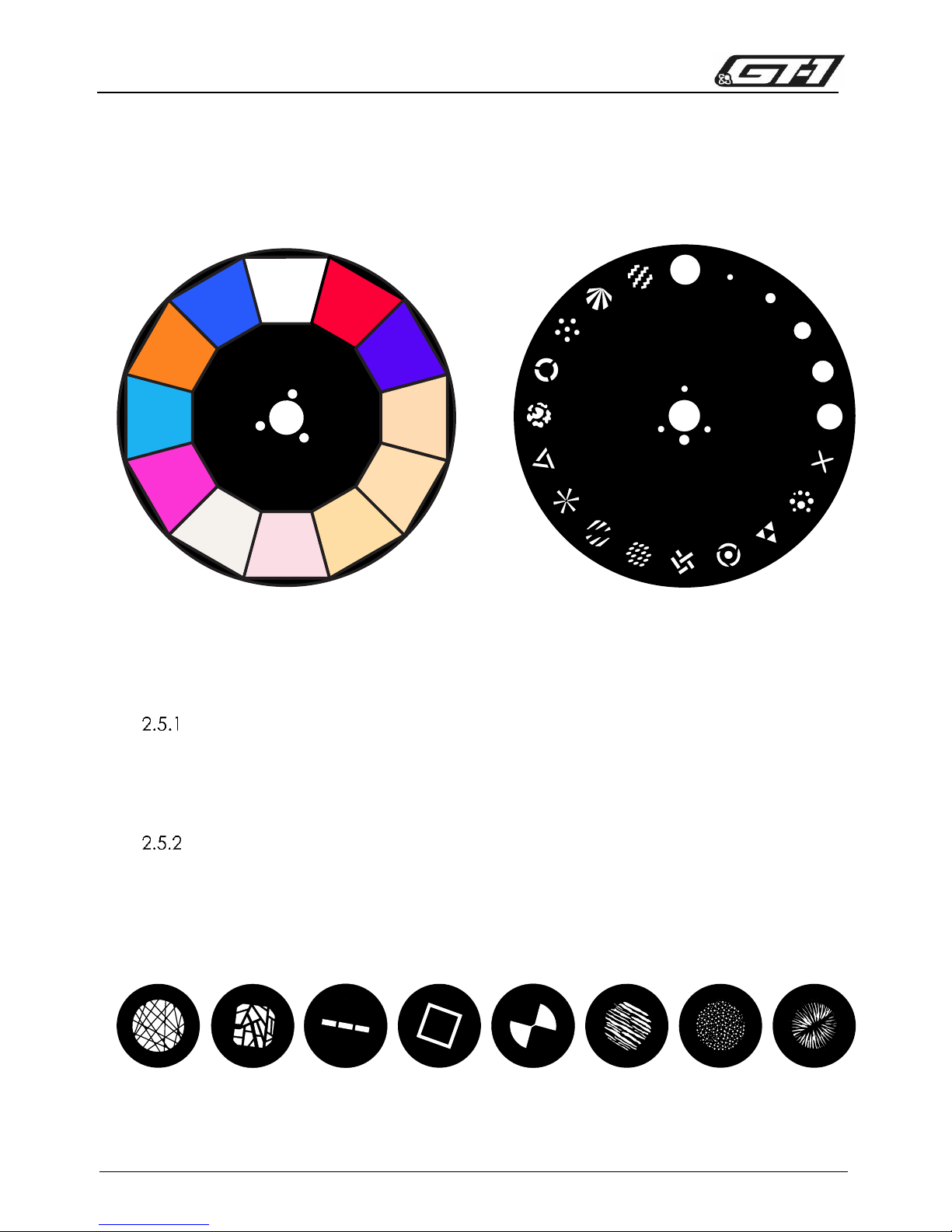
2.5 Gobos .......................................................................................................................7
2.6 Dimming and Shutter Effects .................................................................................8
2.7 Focus and Zoom......................................................................................................8
2.8 Animation Wheel.....................................................................................................8
2.9 Prisms and Frost........................................................................................................9
2.10 Changing Effect Settings by DMX ........................................................................9
2.11 Display.......................................................................................................................9
2.12 Base and rigging options .......................................................................................9
3Preparation for Use.................................................................................................... 10
3.1 Included Items .......................................................................................................10
3.2 Safe Handling ........................................................................................................10
3.3 Mounting ................................................................................................................11
3.4 Securing the Fixture...............................................................................................13
3.5 Connections...........................................................................................................14
3.6 Start/stop operation..............................................................................................14
3.7 Transportation and Storage.................................................................................14
4The Menu Field........................................................................................................... 15
5DMX Channels ........................................................................................................... 18
5.1 Normal Mode (23 DMX Channels)......................................................................18
6Optional Accessories................................................................................................ 20
7Cleaning and Maintenance..................................................................................... 21
7.1 Suggested Maintenance Intervals .....................................................................21
7.2 Cleaning.................................................................................................................21
7.3 Lubrication .............................................................................................................21
7.4 Head Maintenance ..............................................................................................22
7.5 GLP Service and Support .....................................................................................27
8Technical Specifications........................................................................................... 28
9Dimensions................................................................................................................. 30

WWW.GLP.DE
4 Instruction Manual
1Safety Precautions
The GT-1 and this instruction manual are intended for use by experienced
professionals with the knowledge and skills to set up, operate, and maintain high-
powered, remotely controlled lighting equipment safely and efficiently. These
operations require expertise that is not provided in this manual.
Read this manual and familiarize yourself with the safety precautions before installing
or using the product. The manufacturer will take no responsibility for damages or
harm caused by disregard for the information in this manual.
Should you have questions about the safe operation of the GT-1, please contact
an authorized GLP distributor, a list of which can be found at www.glp.de.
1.1 DANGER! Prevent Hazards that Will Result in Serious Injury or Death
Avoid direct exposure to a hot or operating lamp. Discharge lamps operate at high
internal pressure and can explode without warning. The extremely hot shards of
broken glass from an unshielded lamp will cause serious injury. Looking directly at an
unshielded lamp can cause serious eye damage. Direct exposure to UV radiation
can cause skin burns. Operate the lamp only with all covers in place. Turn off the
lamp and allow to cool for at least 60 minutes before removing any head cover.
Wear safety goggles whenever the lamp is exposed.
1.2 WARNING! Prevent Hazards that Could Result in Serious Injury or Death
Do not look directly into the beam of light: brief exposure can cause eye injury. Avoid
exposing your eyes to direct radiation! Do not view the light output with optical
instruments or any device that may concentrate the beam. Risk Group 2 product
according to EN 62471.
Do not illuminate surfaces within 16 M (52.5 ft.) of the fixture. When concentrated in
a narrow beam, the light output is powerful enough to cause burns or fire in
illuminated objects at near range.
Installation shall be performed by qualified personnel only in accordance with local
regulations. To prevent falls, suspend the GT-1 with hardware specifically designed
and rated for the purpose and a form of backup attachment such as a safety cable.
Hot surfaces! Avoid touching lights during the operation. This can cause injuries
and/or damage. Avoid placing lighting fixtures in locations where there is risk of
accidental contact. Allow fixtures to cool before handling.
Connect the fixture only to a grounded (earthed) power supply with overload
protection for protection against electric shock. Verify that power cables and
connectors are in good condition. Replace a blown fuse with one of the specified
rating only.
1.3 CAUTION! Prevent Hazards that Could Result in Moderate Injury
Avoid using strobe effects for extended periods. Flashing light, particularly between

German Light Products GmbH
Instruction Manual 5
5 and 30 flashes per second, may cause seizures in persons with photosensitive
epilepsy. Check local regulations on use of strobe lighting and notify the public in
advance when strobe effects are used. If a seizure occurs, stop using strobe effects.
Help the person sit in a safe place or lay them on their side with their head supported
to prevent it from hitting the floor. Do not use force. Seek emergency medical help if
the seizure lasts for more than a few minutes.
Do not operate a fixture with damaged, cracked, or missing pieces. All optical
components and covers must be in good condition to prevent injury from UV
radiation.
The lamp contains mercury. Do not attempt to clean or repair damage from a
broken lamp. Special safety precautions must be taken. Refer the fixture to an
authorized service facility.
The fixture is heavy. When handling, use a two-person lift to prevent injury.
1.4 NOTICE! Prevent Damage to Product or other Property
Avoid pointing the front of the fixture towards direct sunlight
or other strong light sources. The front lens focuses and
concentrates light just like a magnifying glass. Direct
sunlight and other bright light sources can cause internal
damage to the fixture, melting components or starting an
internal fire within seconds.
Damage can occur whether the fixture is powered on or off. To avoid problems:
Never expose the front of a fixture to direct sunlight or any other strong light sources.
For outdoor applications during daylight, make sure that the front face of any fixture
is shielded or points away from the sun, even when not in use.
Avoid pointing other high-powered beam lights directly at the fixture.
Ensure that the moving head can rotate through its full range of motion before
powering up the fixture, and that fans and air vents are clean and unobstructed.
Do not pick up or carry the fixture by the front lens bezel. The LCD display is also
fragile. Picking up or supporting the fixture in these spots could result in damage
that is not be covered by the warranty.
Use only original spare parts. Any structural modification on the system will terminate
all warranty claims.
Do not exceed 1500 lamp hours. Risk of damage from lamp explosion increases as
the lamp approaches its specified usage life. For best performance, replace the
lamp after 1000 hours of operation.
Clean optical components only as directed. Oils, solvents, and other chemicals
commonly used for cleaning can damage the lens coatings and surfaces.

WWW.GLP.DE
6 Instruction Manual
2Overview of Features
2.1 Intended Use
The GT-1 is for permanent or temporary indoor use in venues where the distance to
illuminated surfaces is at least 16 M (52.5 ft.). It may be used outdoors if it is protected
from moisture and precautions are taken to prevent damage from direct sunlight.
It may be placed upright on a level surface or suspended from a suitable structure
as described in Section 3.3.
It is not suitable for household use, wherever unattended children have access to
it, for permanent outdoor installation, or in areas where the distance from the fixture
to illuminated surfaces is less than specified.
The GT-1 shall be installed, operated, and maintained only by persons with the
training, knowledge and skills to do safely and efficiently.
2.2 Lamp
The GT-1’s OSRAM SIRIUS HRI 440W lamp is a compact reflector lamp with a very
short arc and high light output optimized to create sparkling effects. The lamp was
developed specifically for moving heads to perform in any position. It outputs
22,000 lumens at a color temperature of 7300K with a color rendering index of 80.
The lamp’s average rated life is 1500 hours. It should be replaced every 1000 hours
to minimize the risk of lamp explosion.
2.3 Pan and Tilt
The GT-1 pans through 640° and tilts through 262° with coarse and fine control
channels and self-correcting position feedback. Position feedback can be disabled
and control of pan and tilt can be reversed from the control panel or by DMX.
2.4 Color
The GT-1 provides CMY color mixing with progressively saturated cyan, magenta, and
yellow wheels. The Old CMY curve setting is for use on prototype fixtures that had
different wheels.

German Light Products GmbH
Instruction Manual 7
A separate color wheel supplements the color mixing system with 11 color filters,
including four color correction filters and a light frost filter. The wheel rotates in fixed
color steps, scrolls continuously for split color effects, and rotates clockwise and
counterclockwise with variable speed.
2.5 Gobos
Fixed Gobos
Gobo wheel 2 is an aluminum wheel with 19 patterns, including five iris gobos. The
wheel steps to fixed positions and rotates continuously clockwise and
counterclockwise with variable speed.
Rotating Gobos
Gobo wheel 1 provides eight user-replaceable rotating glass gobos that can be
rotated to indexed positions or continuously with coarse and fine control channels.
Custom gobos shall be 22.9 mm in diameter with a maximum image diameter of 13
mm. They may be manufactured in 0.8 mm 5052 aluminum or 1 mm litho/dichro
coated quartz. See page 23 for the gobo replacement procedure.
1
2
3
4
5
6
7
8
9
10
12
11
13
14
15
16
17
18
19
2
1
3
4
5
6
7
8
9
10
11
Figure 2-1: Color and fixed gobo wheels
1 21 3 4 5 6 7 8
Figure 2-2: Stock rotating gobos

WWW.GLP.DE
8 Instruction Manual
2.6 Dimming and Shutter Effects
The GT-1 features a combined dimmer and shutter system that provides full range
dimming along with flashing pulse and strobe effects up to 10 flashes per second.
Two dimming curves are available: linear and extra soft. The mode can be selected
from the control panel or by DMX.
2.7 Focus and Zoom
The GT-1 has a 3-element optical train with motorized front lens, zoom lens, and
focus lens. The fixture’s two-stage zoom system narrows the focused beam from 56°
down to 3.5° by moving the zoom lens from front to back. It narrows the beam to
2.5° in Beam Mode by moving the front lens forward. The beam may be narrowed
further by inserting iris gobos.
When inserted, the frost filter and prisms are in the path of the zoom lens. When
either of these effects are applied, zoom is not continuous.
Zoom channel values from 82 to 177 are disabled when frost is applied.
Zoom channel values from 107 to 208 are disabled when a prism is inserted.
When taking zoom past these levels in either direction, the frost and prism effects are
automatically removed momentarily.
2.8 Animation Wheel
The GT-1’s animation wheel can be inserted gradually to positions that, when
combined with variable speed clockwise and counterclockwise rotation, give the
appearance of vertical, diagonal, or horizontal movement in two directions.
Figure 2-3: Animation wheel

German Light Products GmbH
Instruction Manual 9
2.9 Prisms and Frost
The GT-1 provides three rotating prisms: a 3-facet, an 8-facet, and a 4-facet linear.
The prisms can be rotated to indexed positions or continuously at variable speed.
Inserting or removing a prism with zoom at a DMX level from 107-208 will cause a
small change in the zoom lens position.
The GT-1 has a split-flag variable frost filter that provides a wide angle wash effect.
Inserting or removing frost at zoom levels from 82-177 will cause a small change in
the zoom lens position.
2.10 Changing Effect Settings by DMX
The Control Channel (23 in Normal DMX Mode) provides the ability to change fixture
settings, turn the lamp on/off, and perform a fixture reset from the control desk. To
send a send a Control Channel command, start from level 0 and hold the
command for three seconds.
2.11 Display
The illuminated graphic LCD display with touch wheel control and self-charging
battery allows you to change fixture settings quickly and intuitively under any
conditions, even when the power is off. See Chapter 4 for settings, readouts, and
related information.
2.12 Base and rigging options
The base provides Camlock attachment points for easy fastening of the included
floor stand, omega clamp attachment brackets, and other rigging accessories. It
also provides 2 M10 threaded sockets for direct fastening of half-coupler clamps.
Two countersunk bolts are provided for clamp attachment.

WWW.GLP.DE
10 Instruction Manual
3Preparation for Use
3.1 Included Items
The GT-1 package includes a floor stand, a power cord with PowerCON connector,
and two M10 x 25 countersunk bolts for fastening half-couplers.
3.2 Safe Handling
Caution! Heavy object. Two person lift required.
Cardboard packaging
To remove a GT-1 from cardboard packaging, open the top of the box and remove
the floor stand and upper piece of foam packing material. Use the cutouts in the
lower piece of foam located by the yoke and base to place hands under fixture. Lift
fixture straight up, out of box, and lower gently onto workspace.
Flight case
To remove a GT-1 from a flight case, mount two omega brackets with handles to the
base. The brackets mount with two Camlock quarter-turn pins. Line up and insert the
pins into the base and turn 90° clockwise to lock. Lift the fixture straight up, out of the
flight case, and lower gently onto workspace.
Installation shall be performed by qualified personnel only, in accordance
with applicable regulations such as BGV C1 and DIN VDE 0711-217.

German Light Products GmbH
Instruction Manual 11
3.3 Mounting
The GT-1 may be rigged in any orientation or placed on a level surface. When
installing, keep the lighting head at least 0.5 m (20 in.) from flammable materials
including curtains and stage scenery.
Accessories are available to mount the GT-1 in various positions. These fasten to the
connectors on the base to ensure safe and stable installation.
Figure 3-1: Mounting Options

WWW.GLP.DE
12 Instruction Manual
Mounting Upright on a Level Surface
For upright installation on a level surface, fasten the floor
stand shipped with the fixture to the base. The floor stand
mounts to the base with two Camlock quarter-turn pins.
Line up and insert the pins into the base and turn 90°
clockwise to lock. Do the opposite to release them.
There are eyelets on both sides of the floor stand that a
ratchet strap can be passed through for additional
bracing if necessary.
Head Down Mounting
To hang the GT-1 with the head down, mount two omega brackets to the base and
fasten a suitable rigging clamp to each omega bracket. The brackets mount to the
base with two Camlock quarter-turn pins. Line up and insert the pins into the base
and turn 90° clockwise to lock. Do the opposite to release them.
Alternatively, two suitable clamps may be bolted directly to the base with suitable 12
mm diameter hardware. Two countersunk 12 mm screws are shipped with the fixture
for this purpose. Notice! The threaded holes are 19 mm (3/4”) deep. Use fasteners that
reach at least 11 mm (7/16 in.) and no more than 19 mm (3/4 in.) into the threaded
hole.
Secure as directed in section 3.4.
Strap eyelet
M10
Gewinde
Camlock Camlock
thread
Figure 3-2 Upright Mounting Details
Camlock pin

German Light Products GmbH
Instruction Manual 13
Sideways Mounting
For sideways mounting, the fixture may be clamped to a vertical truss using two
clamps. See section 3.3.2 above for clamp installation options. Do not attempt to
mount the GT-1 sideways from a horizontal truss.
A dedicated mounting bar, available from GLP as an accessory, may be used to
hang the GT-1 on a vertical support. The mounting bar fastens to the base with
Camlock quarter-turn pins. Line up and insert all four pins into the base and turn 90°
clockwise to lock. Fasten two suitable half-coupler rigging clamps to the mounting
bar to hang the fixture on a truss.
3.4 Securing the Fixture
Warning! Use a secondary attachment (safety wire) that can hold at least 10 times
the weight of the fixture whenever hanging the fixture. Two eyes are provided on the
base for this purpose. Pass the safety wire through the eye in the base and through
or around the truss or supporting structure.
Figure 3-4: Sideways Mounting
Figure 3-3: Omega Clamp Detail

WWW.GLP.DE
14 Instruction Manual
3.5 Connections
Power
The GT-1 provides a 3-conductor, 20 A Neutrik powerCON socket for connection to
AC power. The autosensing power supply accepts 100-240 V, 50/60 Hz AC power. Do
not connect the fixture to any other voltage or an external dimmer.
To prevent arcing at the power connection, turn the power switch off before
connecting or disconnecting a live power cable. Verify that the head is unlocked
before turning the fixture on.
The main fuse is located in a holder in the base. WARNING! Always disconnect the
fixture from the mains supply before replacing the fuse. Replace only with fuse of the
specified type.
Control Data
The GT-1 provides both 3-pin and 5-pin XLR input/output sockets for connection to a
USITT DMX-512 Standard data link. Use only one input and one output. The pin
connections are Pin 1 = [Ground] / Pin 2 = [-] / Pin 3 = [+]. Pins 4 & 5 on the 5-pin
sockets have no contact. Both DMX inputs are connected to both DMX outputs.
The fixture is ACN ready and provides a Neutrik RJ-45 socket for connection to an
ArtNET II compatible Ethernet network.
3.6 Start/stop operation
To start or stop operation, flip the power switch to the “I” (on) or “O” (off) position.
3.7 Transportation and Storage
The GT-1 should be transported either in a flight case or its original packaging to
protect it from damage from shocks during transportation.
When not installed, store the fixture in a dry location.
The AC supply shall provide earth ground connection and overload
protection. Before applying power, verify that the head is unlocked and
can move freely.
Figure 3-5: GT-1 connection sockets

German Light Products GmbH
Instruction Manual 15
4The Menu Field
The LCD display provides access to user settings,
readouts, lamp control, and utilities.
From left to right, the top line of the main menu
displays:
main CPU software version
pan, tilt, and zoom modes: N(ormal) or I(inverse)
DMX mode
dimming mode: L(inear) or E(xtra Soft)
In the example shown in Figure 4-1, the fixture is running software version .71; with
normal pan, inverted tilt, and normal zoom; Normal 23 channel DMX mode; and
linear dimming.
When booting up, the panel displays two screens of fixture information including
component firmware and hardware versions and fixture and lamp hours before
displaying the PCB reset status screen.
Following the label for each effect motor, the reset status screen displays either “---“
(standby), “run”, “ok”, or “err” while the reset is in progress. When completed, the
panel displays the main menu. A flashing display indicates loss of DMX.
Turn the control dial to scroll menu options. Press the Enter button to select a setting,
issue a command, or enter a submenu. Press the Mode button to escape and return
to the top of the menu.
DMX control is disabled when the menu is active.
Figure 4-2: Example of boot sequence and reset displays
Figure 4-1: Menu display

WWW.GLP.DE
16 Instruction Manual
Menu Selection
Value
Remarks
DMX Start Address
1-490
Set the DMX start address
Special
Set dimming mode*
ESOFT
-
Softer, nonlinear dimming
LIN
-
Linear dimming
Show Errors
-
Display error messages
DMX hold*
ON/OFF
Hold last values if DMX signal drops
Test mode
ON/OFF
Run a test sequence
Default*
-
Return all user settings to default values
Temperature main
XX
Readout temperature on main PCB(°C)
Temperature base
XX
Readout temperature in base (°C)
Temperature head
XX
Readout temperature in head (°C)
Boot count
XX
Read number of fixture starts
Fixture hours
XX
Read total fixture hours
Lamp strikes
XX
Read number of lamp starts
Lamp hours
XX
Read number of lamp hours
Reset lamp hours
-
Set hours and strikes counters to 0
Adjust
Key Code
0-255
Enter code to access menu
Pan offset
-99 to 99
Enter position offset values
Tilt offset
Beam lens offset
Zoom offset
Frost1 offset
Frost2 offset
Prism Position offset
Prism Rotation offset
Focus offset
RotGobo Pos. offset
RotGobo Rot. offset
FixGobo offset
ColorWheel offset
Cyan offset
Cyan offset fine
Magenta offset
Magenta offset fine
Yellow offset
Yellow offset fine
Shutter1 offset
Shutter2 offset
LBAM test mode
ON/OFF
Initiate test
*
May be set remotely by DMX

German Light Products GmbH
Instruction Manual 17
Serial
1-9999
Enter user-defined ID number
Lamp on*
-
Switch lamp on
Lamp off*
-
Switch lamp off
Old CMY curve*
ON/OFF
Select dimming curve for early CMY
flags
Position feedback*
ON/OFF
Toggle position feedback
Reverse pan*
ON/OFF
Reverse pan control
Reverse tilt*
ON/OFF
Reverse tilt control
Reverse zoom*
ON/OFF
Reverse zoom control
Reset pan/tilt only*
-
Reset pan/tilt movement
Reset head only*
-
Reset effects in head
Reset*
-
Reset everything
*
May be set remotely by DMX

WWW.GLP.DE
18 Instruction Manual
5DMX Channels
5.1 Normal Mode (23 DMX Channels)
Channel
Function
Time & Value
Percent
DMX
1
Pan, MSB
coarse pan (high/8-bit)
0-640°
0-100%
0-255
2
Pan, LSB
fine pan (low/16-bit)
0-100%
0-255
3
Tilt, MSB
coarse tilt (high/8-bit)
0-262°
0-100%
0-255
4
Tilt, LSB
fine tilt (low/16-bit)
0-100%
0-255
5
Color Wheel
color wheel position and
rotation
(1) open
(2) primary red
(3) primary blue
(4) CTO 4200
(5) CTO 3200
(6) CTO 5600
(7) half minus green
(8) light frost
(9) vivid pink
(10) cyan
(11) medium orange
(12) Congo blue
color scroll / split colors
negative rotation, fast to slow
rotation stop
positive rotation, slow to fast
0-1%
2%
4%
5%
7%
8%
10%
12%
13%
15%
16%
18%
19-65%
66-82%
83%
84-100%
0-3
4-7
8-11
12-15
16-19
20-23
24-27
28-31
32-35
36-39
40-43
44-47
48-167
168-211
212
213-255
6
Cyan
cyan color mixing
no cyan to full cyan
0-100%
0-255
7
Magenta
magenta color mixing
no magenta to full magenta
0-100%
0-255
8
Yellow
yellow color mixing
no yellow to full yellow
0-100%
0-255
9
Gobo Wheel 1
rotating gobo selection
(1) Open
(2) Pick Up Sticks
(3) Window Grills
(4) Dotted Lines
(5) Square Outline
(6) Fan Flags
(7) Linear
(8) Speckle
(9) Explosion
0-12%
14-23%
24-33%
35-44%
46-54%
56-65%
66-75%
77-86%
88-100%
0-33
34-60
61-87
88-114
115-140
141-167
168-194
195-221
222-255
10
Gobo Indexing /
Rotation, MSB
coarse gobo indexing &
rotation
coarse indexing, 0-360°
negative rotation, fast to slow
rotation stop
positive rotation, slow to fast
0-49%
50-74%
75%
76-100%
0-127
128-191
192
193-255
11
Gobo Indexing /
Rotation, LSB
fine gobo indexing &
rotation
fine indexing/rotation speed
0-100%
0-255
12
Gobo Wheel 2
fixed gobo selection
(1) open
(2) gobo 01
(3) gobo 02
(4) gobo 03
(5) gobo 04
(6) gobo 05
(7) gobo 06
(8) gobo 07
(9) gobo 08
(10) gobo 09
(11) gobo 10
(12) gobo 11
(13) gobo 12
(14) gobo 13
(15) gobo 14
0-1%
2%
4%
5%
7%
8%
10%
12%
13%
15%
16%
18%
19%
21%
22%
0-3
4-7
8-11
12-15
16-19
20-23
24-27
28-31
32-35
36-39
40-43
44-47
48-51
52-55
56-59

German Light Products GmbH
Instruction Manual 19
12
Gobo Wheel 2
continued
fixed gobo selection
(16) gobo 15
(17) gobo 16
(18) gobo 17
(19) gobo 18
(20) gobo 19
negative rotation, fast to slow
rotation stop
positive rotation, slow to fast
24%
25%
27%
29%
30%
32-65%
66%
67-100%
60-63
64-67
68-71
72-75
76-79
80-167
168
169-255
13
Shutter
shutter and strobe
effects
closed
random pulse, slow to fast
fade-in pulse, random slow to fast
fade-out pulse, random slow to fast
fade-in/out pulse, rnd slow to fast
flash, delayed 5 sec. to 1 sec.
strobe effect, 1 to 10 Hz
shutter open
0-5%
7-18%
19-30%
32-43%
44-55%
56-77%
79-93%
94-100%
0-15
16-47
48-79
80-111
112-143
144-199
200-239
240-255
14
Dimmer
dimmer
open to closed
0-100%
0-255
15
Focus, MSB
coarse focus (low/8-bit)
near to infinity
0-100%
0-255
16
Focus, LSB
fine focus (high/16-bit)
near to far
0-100%
0-255
17
Zoom
zoom angle
zoom angle, wide to near
beam mode
0-91%
92-100%
0-234
235-255
18
Frost
insert frost filter
full out to full in
0-100%
0-255
19
Prism
prism selection
open (no prism)
8-facet
3-facet
4-facet linear
0-25%
26-49%
50-73%
74-100%
0-66
67-127
128-188
189-255
20
Prism Rotation
prism indexing and
rotation
index 0-360°
negative rotation, fast to slow
rotation stop
positive rotation, slow to fast
0-49%
50-74%
75%
76-100%
0-127
128-191
192
193-255
21
Effect Wheel
insert effect wheel
full out to full in
0-100%
0-255
22
Effect Wheel
Rotation
effect wheel rotation
rotation stop
negative rotation, fast to slow
rotation stop
positive rotation, slow to fast
0%
1-49%
50%
51-100%
0
1-127
128
129-255
23
Control Channel
fixture control: set to
level 0 before sending
command, hold
command for 3 seconds
enable commands
reserved
new CMY curve
old CMY curve
reset head (only)
lamp off
no function
lamp on
Esoft dimmer curve
linear dimmer curve
disable position feedback
enable position feedback
disable DMX hold
enable DMX hold
zoom inverse, Off
zoom inverse, On
tilt inverse, Off
tilt inverse, On
pan inverse, Off
pan inverse, On
factory defaults
fixture reset
0%
1-68%
69%
71%
72%
74%
76%
77%
79%
80%
82%
83%
85%
87%
88%
90%
91%
93%
94%
96%
97%
99-100%
0
1-175
176-179
180-183
184-187
188-191
192-195
196-199
200-203
204-207
208-211
212-215
216-219
220-223
224-227
228-231
232-235
236-239
240-243
244-248
249-251
252-255

WWW.GLP.DE
20 Instruction Manual
6Optional Accessories
Accessory
Part Number
Notes
Omega bracket
87070
For attachment of rigging clamps. 2 required.
Omega bracket with handle
87072
For lifting. 2 required.
Trussbar
call
For sideways rigging.
Table of contents
Other GLP Dj Equipment manuals

GLP
GLP JDC Line 500 User manual

GLP
GLP Impression E350 User manual

GLP
GLP YPOC 575 COLOR User manual

GLP
GLP Impression Series User manual

GLP
GLP inmpression E 350 User manual

GLP
GLP impression X4 Bar 20 User manual

GLP
GLP KNV Series User manual

GLP
GLP impression FR1O BAR User manual

GLP
GLP VOLKSLICHT R-G-B User manual

GLP
GLP Impression X5 IP Bar 1000 User manual

GLP
GLP JDC Line 500 User manual

GLP
GLP impression x4 bar Quick start guide

GLP
GLP impression FR1 TM User manual

GLP
GLP Junior Scan 3 User manual

GLP
GLP IMPRESSION X4L User manual

GLP
GLP Fusion Par FP7 User manual

GLP
GLP impression s350 User manual

GLP
GLP YPOC 575 User manual

GLP
GLP X4 ATOM series User manual

GLP
GLP JDC1 User manual