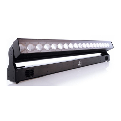
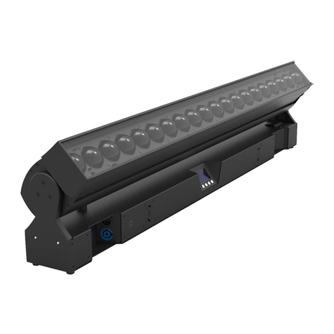
GLP impression X5 User manual

User Manual
impression X5
Document revision: 20220720-01
Fixture software version 1.0.0

Document revisions
Revision number
Notes
Date released
20220720-01
First version available.
Covers firmware v. 1.0.0
July, 2022
GLP® impression X5 User Manual
© 2022 German Light Products GmbH. All rights reserved.
The marks ‘GLP’ and ‘German Light Products’ are trademarks registered as the property of
German Light Products GmbH in Germany, in the United States of America and in other
countries.
The information contained in this document is subject to change without notice. German Light
Products GmbH and all affiliated companies disclaim liability for any injury, damage, direct or
indirect loss, consequential or economic loss or any other loss occasioned by the use of, inability
to use or reliance on the information contained in this document.
Manufacturer’s head office:
German Light Products GmbH (GLP), Industriestrasse 2, 76307 Karlsbad, Germany
Tel (Germany): +49 7248 92719 - 0
Service & Support EMEA:
GLP, Industriestrasse 2, 76307 Karlsbad, Germany
Tel. (Germany): +49 7248 9271955
www.glp.de
Service & Support USA:
GLP USA, 1145 Arroyo St., Ste. A, 91340 San Fernando, California
Tel (USA): +1 818 767 8899
Support (US): info@germanlightproducts.com
www.germanlightproducts.com

Table of Contents
1. Safety..................................................................................................................... 5
Key to symbols................................................................................................. 5
GLP Service and Support ............................................................................... 6
Avoiding damage to the fixture ................................................................... 6
2. Features................................................................................................................. 7
Light source...................................................................................................... 7
Control options................................................................................................ 7
Pan and tilt....................................................................................................... 7
Zoom................................................................................................................. 8
Main and Sub modules .................................................................................. 8
Subfixture Mode .............................................................................................. 8
Color Mix Mode............................................................................................... 9
Mix Priority ........................................................................................................ 9
Color temperature control (CTC) ............................................................... 10
Color Quality Control (CQC)....................................................................... 10
Magenta/Green Shift (M/G Shift) ............................................................... 11
Color wheel ................................................................................................... 11
Tungsten simulation....................................................................................... 11
Shutter ............................................................................................................ 12
Dimmer........................................................................................................... 13
Individual Segment or Pixel Control............................................................ 13
Pattern Control.............................................................................................. 14
Special/Control DMX channel .................................................................... 15
Accessory channels 1and 2......................................................................... 15
3. Settings ................................................................................................................ 16
Color Mix Mode............................................................................................. 16
White point..................................................................................................... 16
Performance settings.................................................................................... 17
Fan modes ..................................................................................................... 17
Subfixture Mode ............................................................................................ 18
PWM Frequency............................................................................................ 18
Pixel mirror ...................................................................................................... 19
Pixel rotation .................................................................................................. 19
No signal......................................................................................................... 20
Pan Invert ....................................................................................................... 20
Tilt Invert.......................................................................................................... 20
Position feedback......................................................................................... 20
Pan Range ..................................................................................................... 21
Accessories and tilt range ........................................................................... 21
Display Mode................................................................................................. 21
Display Orientation ....................................................................................... 21
Hibernation .................................................................................................... 21
Load User Settings......................................................................................... 22
Information..................................................................................................... 22
Manual Control ............................................................................................. 22
Manual DMX.................................................................................................. 22

Service............................................................................................................ 23
Advanced Service........................................................................................ 23
Load Factory Defaults .................................................................................. 24
Factory Menu ................................................................................................ 24
4. Control panel...................................................................................................... 25
Default information screen .......................................................................... 25
Using the control panel ................................................................................ 26
Control button shortcuts .............................................................................. 27
Error codes ..................................................................................................... 28
Loss of DMX signal ......................................................................................... 28
5. Setting up the control protocol........................................................................ 29
6. Control menus .................................................................................................... 30
Quick menu ................................................................................................... 30
Main menu..................................................................................................... 31
7. Error codes .......................................................................................................... 36
8. DMX control modes overview .......................................................................... 37
9. DMX control channel layout............................................................................. 42
Pixel positions ................................................................................................. 42
10.Key to conversion of x and y coordinates ...................................................... 75
11.Color wheel specifications................................................................................ 76

German Light Products®
Rev. 20220720-01 5
1. Safety
Key to symbols
The following symbols are used in the product’s user documentation:
Warning! Read the Quick Start and Safety Manual supplied with the
impression X5 lighting fixture and available for download from www.glp.de
before installing, operating or servicing the fixture. The Quick Start and
Safety Manual contains important information for the safe use of impression
X5 fixtures. If you fail to read that information, you may create a safety
hazard with a risk of injury, death or damage.
If you have any doubts or questions about how to use the product safely, please
contact your GLP® supplier, who will be happy to help.
The user documentation for GLP impression X5 lighting fixtures consists of:
●The impression X5 Quick Start and Safety Manual, supplied with impression X5
fixtures and available for download from www.glp.de. The Quick Start and Safety
Manual contains important safety information and installation instructions that the
installer and user must read. It also contains a detailed product overview,
dimensions drawings and technical specifications for the product.
●The impression X5 User Manual, available for download from www.glp.de. The User
Manual explains features and control of impression X5 fixtures.
●The impression X5 DMX Channel Index, containing the DMX control channel layout
and DMX commands available in the fixture. This information is also included in the
User Manual.
The impression X5 is intended for use by experienced professionals with the knowledge
and skills to set up, operate, and maintain high-powered, remotely controlled lighting
equipment safely and efficiently. These operations require expertise that may not be
provided in this manual.
Warning! Safety hazard.
Risk of severe injury or
death.
Warning! Hazardous voltage.
Risk of lethal or severe
electric shock.
Warning! See user
documentation for
important safety
information.
Warning! Fire hazard.
Warning! Risk of eye
injury.
Warning! Hot surface. Risk of
burn injury.

www.glp.de
6 impresssion X5 User Manual
●Respect all warnings and directions given in the product’s user documentation and
on the product. Read the user documentation and familiarize yourself with the
safety precautions it contains before installing, using or servicing the product. GLP
and affiliated companies will take no responsibility for damage or injury resulting
from disregard for the information in the user documentation.
●Check the GLP website at www.glp.de and make sure that you have the latest
versions of the product’s user documentation.
●Check the fixture software version indicated on page 2 of this User Manual and
then use the fixture’s control panel to check the version installed in the fixture. If the
versions are not the same, the user manual may still cover the fixture, because
software updates do not always affect the use of the fixture. However, it is possible
that this User Manual does not match the fixture perfectly. Software release notes
can help clarify this question. You can consult software release notes and
download the correct version of this manual on the GLP website if necessary.
●Make both the Quick Start and Safety Manual and this User Manual available to all
persons who will install, operate or service the product. Save both documents for
future reference.
●If you have any questions about the safe operation of the product, please contact
an authorized GLP distributor (see list of distributors at www.glp.de).
●Use the product only as directed in this manual. Observe all markings in this manual
and on the product.
GLP Service and Support
Contact information for the nearest GLP Service and Support is available online at
numbers:
●GLP Germany: +49 (7248) 927 19-55
●GLP N. America: +1 818 767-8899
●GLP UK: +44 1392 690140
●GLP Asia: +852 (3151) 7730
●GLP Nordic: +46 737 57 11 40
Avoiding damage to the fixture
The Quick Start and Safety Manual contains important information that is intended to
help you avoid possible damage to the fixture from other light sources, during
transportation, etc. Read that information before storing, transporting or using the
fixture.

German Light Products®
Rev. 20220720-01 7
2. Features
Light source
The impression X5’s light source is a powerful group of 19 x 40 W RGBL LEDs.
Control options
The impression X5 is compatible with DMX 512 and RDM. See the impression X5 Quick
Start and Safety Manual for more details.
The fixture also features GLP’s FPO (Flexible Protocol Option) Port. This port allows you to
use control options such as LumenRadio CRMX or others on request. Contact your GLP
supplier for details.
Pan and tilt
The impression X5 pans through 540° by default and tilts through 264° with coarse and
fine control channels.
The directions of pan and tilt can be reversed using the control panel or via DMX on
the Special/Control channel.
Pan range can be changed from 540° (Standard) to 650° (Extended) if needed using
the Fixture Settings →Pan range setting (see’Pan Range’ on page 21.
Tilt range can be limited using the Fixture Settings →Accessory setting (see’Accessories
and tilt range’ on page 21) if external accessories are installed on the head.
When the fixture is powered up and no valid DMX signal is present, the head moves
automatically to its home position (center/center).
You can adjust the speed (and noise level) of pan and tilt movement, as well as the
speed of all other mechanical effects, by selecting from three different performance
options using the Fixture Settings →Performance setting (see ‘Performance settings’ on
page 17).
Direction of pan and tilt movement
With the fixture standing on the ground, increasing the pan DMX value moves the yoke
clockwise from its home position. Pan direction can be reversed using the Fixture
Settings →Pan Invert setting (see ‘Pan Invert’on page 20) or via DMX on the
Special/Control channel.
With the fixture standing on the ground, increasing the tilt DMX value moves the head
towards the front from its home position. Tilt direction can be reversed using the Fixture
Settings →Tilt Invert setting (see ‘Tilt Invert’on page 20) or via DMX on the
Special/Control channel.
Pan and tilt position feedback and self-correction
The fixture has a pan/tilt position feedback and self-correction system that brings the
head back to its correct position if it was unintentionally moved. When correcting pan
and/or tilt, the fixture at first tries twice to move to the correct position. If it cannot
move to this position, it waits for a short period and then tries again.

www.glp.de
8 impresssion X5 User Manual
Position feedback is automatically disabled for a short time if you press one of the
control panel buttons on the yoke. This feature lets an operator move the yoke
manually for more convenient use of the control panel and display. Pan and tilt remain
automatically disabled while you are using the fixture’s control panel.
Position feedback can also be set to constantly disabled using the Fixture Settings →
Position Feedback setting (see ‘Position feedback’on page 20) or via DMX on the
Special/Control channel.
Zoom
The impression X5 has a zoom range that lets you vary the beam angle from 3.5° to 37°
(half-peak) / vary the field angle from 4.9° to 57° (one-tenth peak).
Control on the Zoom DMX channel moves from spot to flood as the DMX value
increases.
You can adjust the speed (and noise level) of the zoom effect, as well as the speed of
all other mechanical effects, by selecting from three different performance options
using the Fixture Settings →Performance setting (see ‘Performance settings’ on page
17).
Main and Sub modules
Some control modes divide the fixture into two or more modules (Main module and
Sub modules). For example, Control Mode 2 divides the Washlight into:
●Main module (Layer 1 = one RGB(L) Wash fixture)
●Sub module (Layer 2 = pattern engine with segment or individual pixel control).
The Sub module has its own intensity and shutter channels. Professional controllers will
handle this setup in a smart multi-fixture profile.
The Subfixture Mode setting lets you decide whether the Sub module should be
subordinate to or independent of the Main module (see below).
Subfixture Mode
The fixture offers two different options for control of the Main module and Sub modules
using the Fixture Settings →Subfixture Mode setting (see also ‘Subfixture Mode’ on
page 18):
●Normal mode makes the Sub module channels subordinate to the Main module.
This means that the intensity and shutter of the Main module act as global intensity
and global shutter.
●Independent mode makes the Sub module channels completely independent of
the Main module.

German Light Products®
Rev. 20220720-01 9
Color Mix Mode
The main module of the impression X5 features 16-bit color mixing with RGB, RGBL and
x;y (CIE 1931) color control. You can change the color mixing mode using the Fixture
Settings →Color Mix Mode setting (see ‘Color Mix Mode’ on page 16) or via DMX on
the Special/Control channel.
Sub module color mixing is always RGB.
Mix Priority
The Mix Priority channel defines how the color mixing output of the Main module and
the color mixing output of the Sub module are merged together –or which value has
higher priority –in the X5’s color mixing output.
The default setting (DMX 000) is Main and Sub (HTP),where the highest color value of
the Main or the Sub module determines the output color.
The Mix Priority channel gives the following options:
●Main + Sub (HTP) –The fixture takes whichever color value of the Main module or
Sub module is highest and uses that value to determine the output color (Highest
Takes Priority).
●Main Only –The Sub module color value is ignored. The fixture uses the color value
of the Main module.
●Sub Only –The Main module color value is ignored. The fixture uses the color value
of the Sub module.
●Main + Sub additive –The Sub module color value is added to the Main module
color value. The fixture uses the sum of both values.
●Main - Sub subtractive –The Sub module color value is subtracted from the Main
module color value.
●Sub - Main subtractive –The Main module color value is subtracted from the Sub
module color value.
●TrueColor Main over Sub Snap –Sub module color stays in the background. Main
module color has higher priority and will not mix with Sub module color. As soon the
Main module color value is greater than zero, Sub module color blacks out and the
fixture uses the Main module color.
●TrueColor Sub over Main Snap –Main module color stays in the background. Sub
module color has higher priority and will not mix with the Main module color. As
soon as Sub module color value is greater than zero, Main module color blacks out
and the fixture uses Sub module color.
●TrueColor Main over Sub Crossfade –Sub module color stays in the background.
Main module color has higher priority. If you fade in a Main module color, Sub
module color will crossfade to the Main module color.
●TrueColor Sub over Main Crossfade –Main module color stays in the background.
Sub module color has higher priority. If you fade in a Main module color, Sub
module color will crossfade to the Main module color.

www.glp.de
10 impresssion X5 User Manual
●Main to Sub Crossfade –Manually crossfading from Main module color only →Main
and Sub module color (HTP) →Sub module color only.
Color temperature control (CTC)
The impression X5’s three color mixing control modes (RGB, RGBL and x;y) all offer a
separate Color Temperature Correction channel which lets you shift the color
temperature obtained by the Main module and Sub module when all colors are set to
100% (i.e. R255/G255/B255 in RGB mode or R255/G255/B255/L255 in RGBL mode). A
CTC range of 10 000 K to 2500 K is available.
Depending on the selected Color Mix Mode (RGB, RGBL or x;y), if you select a color
temperature on the CTC channel, the fixture will no longer use the specific open color
and will instead use the selected color temperature.
If you select a color temperature on the CTC channel, it is still possible to manipulate
the color temperature using the RGB and RGBL channels.
Note
To obtain the desired color temperature on the CTC channel, all ColorMix channels
need to be set to 100%. If they are not at 100%, the system will mix color relative to the
selected white point of the CTC channel.
The CTC channel affects all the fixture’s modules. Setting the CTC channel to a specific
color temperature will affect the open white of the Main module and Sub modules.
Color Quality Control (CQC)
The CQC channel lets you modify the spectral mix of the white color output in order to
achieve a balance between better color rendering or higher output. Physically, the
richer light spectrum created when deploying multiple LEDs will give better color
rendering but will also give lower output. On the other hand, you can obtain higher
output if you accept lower color rendering.
While using white colored light, the CQC channel lets you change between white with
priority on high-quality color rendering and white with priority on highest output.
Additionally, the CQC channel lets you smoothly desaturate colors. If you have set a
saturated color in the color mix, the CQC channel lets you smoothly desaturate the
color from saturated to fully unsaturated (= white).
The following options are available:
●High Quality (HQ) –Color is mixed with priority given to the best white color
rendering quality. Saturated colors will have maximum saturation at DMX 000 and
will smoothly become unsaturated until they reach 0% saturation (= white) at DMX
value 127.
●High Output (HO) - Color is mixed with priority given to the highest output in white.
Saturated colors will have maximum saturation at DMX 255 and will smoothly
become unsaturated until they reach 0% saturation (= white) at DMX value 128.

German Light Products®
Rev. 20220720-01 11
Note
The CQC channel affects all the fixture’s modules. Setting the CQC channel to a
specific value will affect the colors of the Main module and Sub modules.
Magenta/Green Shift (M/G Shift)
The Magenta/Green Shift channel lets you move the color coordinate of a white point,
a mixed color or a selected CTC color along a vertical line on the color temperature
curve in all three ColorMix modes. The corresponding white point is either shifted
towards Green or Magenta.
If M/G Shift is enabled, it immediately affects all mixed colors as well as the color
temperature that is selected on the CTC channel. It has no effect on the colors of the
virtual color wheel.
Note
The M/G Shift channel affects the entire fixture. Setting the M/G Shift channel to a
specific value will affect the output of the Main module and Sub modules.
Color wheel
The impression X5 features a virtual color wheel channel that gives quick access to a
wide range of LEE-referenced colors in all three ColorMix modes. Color wheel color
presets are always mixed with the best available spectrum. Color filter color
coordinates are based on a Source C (daylight) light source.
Besides static color presets, the color wheel channel also offers continuous color
scrolling in rainbow colors. When set to Rainbow, the fixture runs through the typical
colors of a rainbow with speed variable from slow to fast.
The crossfade time of a color change is relative to the speed: at slow speeds colors
crossfade smoothly and at fast speeds colors snap.
If a color coordinate is outside the possible color gamut of the light source, the fixture
tries to match the target color as closely as possible.
Note
Color wheel color presets have higher priority than the ColorMix, CTO and M/G Shift
channels.
The virtual color wheel channel must be set to DMX 000 in order to use normal RGB,
RGBL or x:y color mixing.
Tungsten simulation
When a tungsten lamp is dimmed, there is a small delay in intensity changes and there
is a color shift along the black body line. The tungsten simulation channel allows the
user to select between different tungsten options in all three ColorMix modes.

www.glp.de
12 impresssion X5 User Manual
The first part of the Tungsten channel offers standard tungsten features with fixed color
temperature, red shift and delayed intensity changes. The color temperature as well as
the color shift and inertia of the selected light source are fully simulated. Tungsten
mode has higher priority than the color wheel or CTC.
The second part of the Tungsten channel lets you apply one of the corresponding
tungsten effects (color shift and inertia) to the currently set mixed color or currently
selected color temperature on the CTC channel.
Note
The Tungsten channel affects the entire fixture. Setting the Tungsten channel to a
specific value will affect the output of the Main module and Sub module.
Shutter
The impression X5’s shutter channel offers continuous blackout, continuous open and a
range of intensity effects.
Depending on the selected Subfixture Mode, the shutter channel of the Main module
channel group acts as either a master shutter or as the shutter channel of the Main
module independently of the Sub module.
The following shutter effects are available:
●Single flash performs exactly one single flash with each value change within this
DMX value slot.
●Pulse dims up and down smoothly with the same fade-in and fade-out times.
Speed can be adjusted from slow to fast.
●Pulse open fades in and then snaps to blackout. Speed can be adjusted from slow
to fast.
●Pulse close fades out and then snaps to full. Speed can be adjusted from slow to
fast.
●Strobe double flash provides a quick double flash. Speed can be adjusted from
slow to fast.
●Strobe pixel random (only available when the fixture is set to a DMX mode with
individual pixel control) strobes individual pixels at random to give a kind of
sparkling effect. Speed can be adjusted from slow to fast.
●Strobe random strobes all of one fixture’s pixels together at random intervals,
allowing a random strobe between multiple fixtures. Speed can be adjusted from
slow to fast. Note that the random effect across multiple fixtures really is random!
●Strobe strobes all of one fixture’s pixels together and also perfectly synchronizes the
strobe in multiple fixtures so that all the fixtures flash at exactly the same time.
Speed can be adjusted from slow to fast.

German Light Products®
Rev. 20220720-01 13
Note
Depending on the selected Subfixture Mode, the dimmer and shutter channels of the
Sub modules can operate independently of or subordinately to the dimmer and
shutter channels of the Main module.
Dimmer
The electronic dimming effect provides smooth 16-bit dimming of the Main module
and Sub modules.
Dimming curves
See Figure 1. Three dimming curve options are available: Linear, S-Curve and Soft.
●The Linear setting gives a dimming curve that the eye perceives as linear.
●The S-Curve setting gives finer control at lower light levels and at higher light levels,
with coarser control at medium light levels.
●The Soft setting gives finer control at lower light levels, where the eye is most
sensitive to changes in light intensity, and coarser control at higher light levels.
You can select the dimming curve using the control panel or via DMX on the
Special/Control channel.
Note
Depending on the selected Subfixture Mode, the dimmer and shutter channels of the
Sub modules can operate independently of or subordinately to the dimmer and
shutter channels of the Main module.
Individual Segment or Pixel Control
The impression X5 offers 19 individually controllable pixels. Each pixel cell houses a 40 W
RGBL LED that can be controlled individually in intensity and color for creating
dynamic effects and pixel mapping.
Figure 1. Dimming curves

www.glp.de
14 impresssion X5 User Manual
The fixture’s different DMX control modes offer different options for working with the
individual segments or pixels.
●In nearly all DMX modes, the Main module gives color mixing control of all pixels
together as one segment.
●Mode 2 (Normal) adds a Sub module as a second layer with pattern effects and
color mixing of all 19 pixels as one segment.
●Mode 3 (Segment) adds a Sub module as a second layer with pattern effects and
color mixing of the segments: the inner, middle and outer rings.
●Mode 4 (Multipixel Advanced) adds a Sub module as a second layer with pattern
effects and RGB color mixing of each individual pixel.
●Mode 5 is a pure pixel mapping mode which is reduced to the main overall control
options plus RGB color mixing of each individual pixel.
Pattern Control
The impression X5 offers a wide range of static and dynamic pre-programmed FX
patterns on the Sub modules. The Sub module color control channels define the color
of the pattern effects. The Sub module Color Mix Mode is always RGB.
A static pattern is a fixed pattern with only one pattern step. This allows you a very
quick selection of a non-dynamic effect. It has active and inactive pixels. Each active
pixel shows the selected pattern color while each inactive pixel is fully transparent.
A dynamic pattern is a sequence of multiple pattern steps and has active and inactive
pixels. Each active pixel shows the selected pattern color while each inactive pixel is
fully transparent. You can set pattern steps to automatically change continuously
(Pattern Speed) or you can directly select pattern steps (Pattern Index).
Note
The Mix Priority channel lets you decide how the output of the Main module and the
Sub module (pattern or pixel mapping) should be merged.
Pattern selection
The pattern selection channel offers a choice of 59 static patterns, 50 dynamic
patterns and some special patterns. The dynamic patterns offer multiple pattern steps
for individual step selection or continuous pattern step chasers.
Pattern 0 (DMX 000) is the idle pattern and just sets all pixels to active.
The Random Pixel FX pattern at the end of the Pattern Select channel randomly selects
pixels to create an attractive sparkle effect.
Pattern speed/index
As a dynamic pattern is a sequence of multiple pattern steps, you can select:
●an automatic clockwise or counterclockwise continuous run-through of the pattern
steps with different speeds (dynamic speed control = DMX values 002 …127), or

German Light Products®
Rev. 20220720-01 15
●one of the available specific pattern steps (static indexing = DMX values 128 …
255).
Note
Bear in mind that different patterns can have a different number of pattern steps. This
can affect synchronization between fixtures, for example, if you run different patterns
in multiple fixtures.
Pattern Step Crossfade
The Pattern Step Crossfading channel lets you choose how one step in a pattern
should change into the next step. This change can be a snap, a normal crossfade or a
fade with tail (quick fade In and variable long fade out).
Pattern Transition
The Pattern Transition channel lets you choose how a Pattern A should change into
Pattern B. This change can be a snap, a soft crossfade, a Fade Over Blackout (FOB) or
Fade Over Full (FOF).
Special/Control DMX channel
The Special/Control DMX channel lets you change fixture settings and perform a fixture
reset from the control desk (a possibility that can be very useful during a show or for a
specific scene). To apply a command on the Special/Control channel, you must hold
the command for the time indicated in the DMX channel index section at the end of
this user manual.
To trigger a reset using the Special/Control channel, you must send the DMX value for
this function for 3 seconds. If you want to trigger an additional reset using the
Special/Control channel, you must first move away from the Reset DMX value and
then return to this value. This requirement to change DMX values eliminates the risk of
the fixture entering an unwanted Reset loop if it is patched wrongly.
Accessory channels 1and 2
It is possible to install optional electromechanical effect modules on the front of the
impression X5 head. These modules can be supplied with power and control data
using the power and data connection available on the back of the head. The two
accessory channels supply two sets of DMX control data at this connection.

www.glp.de
16 impresssion X5 User Manual
3. Settings
The settings described in this chapter let you customize the impression X5. Settings can
be available in the control panel on the fixture’s yoke, via DMX and/or via RDM.
Color Mix Mode
The Color Mix Mode setting offers three different options for color mixing:
●RGB –RGB Mode mixes color using Red, Green and Blue channels. The Lime LED is
mixed automatically using the fixture’s internal GLP iQ.Gamut algorithm.
RGB Mode also offers a clean default white light at open which is considered to be
the white point (RGB at 100%). Fixed white point selection or temporary CTC
channel value selection lets you set different color temperatures.
M/G shift and CQC adjustment are available in this mode.
●RGBL –RGBL Mode mixes color using Red, Green, Blue and Lime channels. The color
gamut is still calibrated to the X5 range, but the white point (open) is not adjusted
to the black body line and will show a white that is mixed using 100% RGBL.
The CTC channel lets you quickly change to any white on the black body line.
M/G Shift correction is available.
●x;y –x;y Mode lets you send x;y color coordinates to the fixture via DMX. The
internal color algorithm mixes the four LED colors perfectly to match the x:y color
coordinates.
White point setting is disabled. CTC channel values overwrite x:y values.
M/G Shift and CQC adjustment are available in this mode.
Note
Color mixing of Sub modules is always RGB.
White point
White point selection is available in RGB Mode and determines the fixture’s color
temperature at “open”. The following white points (color temperatures) are available:
●8000 K (effect light)
●6500 K (daylight –default)
●5600 K (TV and studio)
●4200 K (CDM)
●3200 K (tungsten)
If a white point is enabled, the fixture mixes colors with reference to it. GLP iQ.Gamut
navigates through the color space using the preferred Color Mode color mixing
method.

German Light Products®
Rev. 20220720-01 17
iQ.Gamut
iQ.Gamut is the new LED calibration technology from GLP. The iQ.Gamut settings let
you choose a calibrated color gamut within which the fixture operates.
●FULL (default): Color mixing is calibrated to the X5 color gamut. This setting gives
best results for applications where deep saturated colors are needed.
●Rec.2020: Color mixing is matched to the limits of the Rec.2020 gamut. This setting
gives best results for UHD TV applications and avoids color clipping.
●Rec.709: Color mixing is matched to the limits of the Rec.709 gamut. This setting
gives best results for HD TV applications and avoids color clipping.
Performance settings
You can select between three different settings for the movement speed of the
fixture’s mechanical effects (pan/tilt and zoom):
●Normal sets mechanical effects movement to give an optimum balance between
speed, quietness and smoothness. Normal is the default setting.
●Fast sets movement to maximum speed. This setting gives very fast effect movement
but can result in higher noise levels.
●Smooth optimizes the smoothness of the mechanical effects and gives lowest-noise
performance. This setting gives extremely low noise and smooth performance, but
effect movement will be slower than in Normal mode.
Fan modes
Five cooling fan modes let you give priority to lowest fan noise or most powerful
cooling:
●Regulated mode gives priority to light output and only operates fans as necessary. If
the fixture is blacked out, fans run at minimum speed. When light output intensity is
increased, temperature regulation increases fan speed to the level necessary to
keep the fixture at optimum temperature.
If light output is set to maximum intensity but the fans can keep the fixture at
optimum temperature, there is no regulation of light intensity. If the fixture begins to
exceed optimum temperature and the fans are running at maximum speed, light
intensity is limited until optimum temperature can be maintained.
●High mode sets the fixture to give maximum light output and suits operation in high
ambient temperatures. Fans are set to constant operation at high speed. Light
output intensity is limited smoothly if it becomes necessary in order to keep fixture
temperature at optimum level.
You can also use High mode to cool down a fixture quickly after a period of
operation or to help remove dust from cooling fans.
●Medium mode sets fans to constant operation at medium speed. Light output
intensity is reduced to a level where it will normally remain constant at ambient
temperatures of up to 45° C (113° F). Intensity is smoothly limited further if it
becomes necessary in order to keep fixture temperature at optimum level.

www.glp.de
18 impresssion X5 User Manual
●Low mode sets fans to constant operation at low speed and is optimized for
minimum noise. Light output intensity is reduced to a level where it will normally
remain constant at ambient temperatures of up to 30° C (86° F). Intensity is
smoothly limited further if it becomes necessary in order to keep fixture temperature
at optimum level.
●Off disables all fans which are not necessary to cool important electronic
components. These fans will rotate as slowly as possible in order to reduce the noise
level to a minimum. Light output intensity is reduced as much as becomes
necessary.
Note
In all fan modes, if fixture temperature reaches a dangerous level, the LEDs are shut
down for a period until the fans have brought the temperature down to a safe level.
Subfixture Mode
The impression X5 offers two different options for controlling the Main module and Sub
modules.
●Normal –In this mode, all Sub module channels are subordinate to the Main
module channel group. This means that the intensity and shutter of the Main
module act as master intensity and master shutter for the whole fixture.
●Independent –In this mode, the Sub module channel group can be controlled
independently of the Main module channel group and act as an independent
fixture.
Note
No matter which Subfixture Mode setting you select:
- The Mix Priority channel is still active and will affect how the two dependent or
independent fixtures will be mixed.
- Some of the general color management channels of the Main module such as CTC,
CQC, M/G-Shift and Tungsten effects will still affect the Sub module.
PWM Frequency
This setting lets you select between different PWM frequencies for different applications
and adjust LED frequencies to give the best results at different camera shutter
frequencies. Changing the PWM frequency can help to avoid flicker and beat
frequencies in video images.
The following PWM settings are available:
●Optimum (defaults) sets the fixture to a PWM frequency of approx. 3000 Hz, which
offers best results when dimming.
●High1 sets the PWM frequency to approx. 4800 Hz
●High2 sets the PWM frequency to approx. 9600 Hz

German Light Products®
Rev. 20220720-01 19
●Max increases the PWM frequency to the highest possible frequency the fixture can
operate at. Use this setting for slow motion video or high speed camera
applications. Dimming resolution at the Max setting is the least smooth when
compared with the other PWM settings.
Note that a higher PWM frequency may affect dimming performance. The PWM
frequency setting is stored in the fixture and is not affected by cycling power off and
on. However, it will be affected if you use the Factory Defaults command in the control
menus. As a rule, you should set all the fixtures in an installation to the same PWM
frequency in order to ensure the same performance.
You can set the PWM frequency using the control panel or the Special/Control DMX
channel.
Pixel mirror
The Pixel mirror setting lets you flip the fixture’s pixel layout on the x-axis, y-axis or both
x- and y-axis:
●Off gives the standard pixel layout:
The drawing above shows the pixel layout with the fixture standing on the ground,
pan at 50% (home position) and tilt at 50% (front).
●x-mirror flips the pixel layout along the x-axis.
●y-mirror flips the pixel layout along the y-axis.
●x:y mirror flips the pixel layout along the x-axis and the y-axis.
Pixel rotation
Lets you rotate the fixture’s pixel layout by: 0° –60° –120° –180° –240° –300°.
X axis

www.glp.de
20 impresssion X5 User Manual
No signal
The No signal settings let you manage how the fixture behaves if no DMX signal is
present (if the fixture is being controlled by DMX but the DMX signal stops, or if you
apply power to the fixture when no DMX signal is present):
●Blackout sets the fixture to black out whenever it is not receiving a DMX signal. This is
the default setting.
●Hold sets the fixture to continue using the last DMX values it received.
●Scene (Stand-alone) sets the fixture to play its stored stand-alone scene (see
Capture DMX Values below) when the fixture is not receiving a DMX signal. If no
stand-alone scene is stored in memory, the fixture will black out.
If the fixture is set to Scene (Stand-alone) and if a stand-alone scene has been
stored in its memory using the Capture DMX Values command, it will display its
stand-alone scene at all times when it is powered on but not receiving a DMX
signal. You can therefore use this setting if you want fixtures to automatically start
stand-alone operation when you apply power to them.
●Capture DMX Values takes a snapshot of the DMX values that are currently being
received and stores them in the fixture’s memory as its captured scene. The fixture
will display this scene if it is set to Scene (Stand-alone) (see above) and is not
receiving a DMX signal.
Pan Invert
Reverses the direction of pan.
●Off –In the normal setting, increasing the pan value turns the yoke clockwise (as
seen with the fixture standing on the ground).
●On –In the inverted setting, increasing the pan value turns the yoke
counterclockwise (towards the grey safety eyelet).
Tilt Invert
Reverses the direction of tilt.
●Off –In the normal setting, increasing the tilt value turns the head to the FRONT
(towards the black safety eyelet).
●On –In the inverted setting, increasing the tilt value will turn the head to the BACK
(towards the grey safety eyelet).
Position feedback
Manages pan and tilt auto-correction.
●Pan and tilt position feedback is normally enabled (Position Feedback = On).
●If disabled (Position Feedback = Off), the fixture will not auto-correct pan and tilt
position.
If you need to return pan and tilt to their correct positions, you must perform a reset.
Other manuals for impression X5
2
Table of contents
Other GLP Dj Equipment manuals

GLP
GLP POCKET SCAN User manual

GLP
GLP YPOC 575 COLOR User manual

GLP
GLP Startec-1200 User manual

GLP
GLP YPOC 575 User manual

GLP
GLP IMPRESSION X4L User manual

GLP
GLP Impression Series User manual

GLP
GLP JDC Line 500 User manual

GLP
GLP Impression X5 IP Bar 1000 User manual

GLP
GLP impression FRIO BAR User manual

GLP
GLP GT-1 User manual

GLP
GLP inmpression E 350 User manual

GLP
GLP 7687 User manual

GLP
GLP YPOC 250 Color User manual

GLP
GLP YPOC CMY 700 User manual

GLP
GLP ION.SPOT User manual

GLP
GLP Fusion Par FP7 User manual

GLP
GLP Impression E350 User manual

GLP
GLP Impression XL User manual

GLP
GLP impression x4 bar Quick start guide

GLP
GLP X4 ATOM series User manual