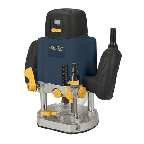
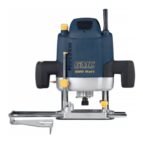
GMC GR710 User manual

Version date: 24.04.17
710W
PLUNGE & TRIMMER
1/4" ROUTER
GR710
INVAL EN TRIMMER BOVENFREES, 1/4"
DÉFONCEUSE AFFLEUREUSE 1/4"
TAUCH- UND KANTENFRÄSE, 1/4ZOLL
FRESATRICE AD IMMERSIONE E DA TAGLIO1/4"
FRESADORA MULTIFUNCIÓN 1/4"
FREZARKA GÓRNOWRZECIONOWA/
PRZECINARKA 710 W 1/4"
732455_MANUAL.indd 1 24/04/2017 16:40

1 2 3
4
5
21
22
23
24
25
26
27 28
29
13
14
15
16
17181920
6
7
8
9
30
31 32
33
34
35
36
10
11
12
732455_MANUAL.indd 2 24/04/2017 16:40

45
55
53 54
51
52
50
49
16
56
46
47
48
40 41 42
43
44
37
38
39
732455_MANUAL.indd 3 24/04/2017 16:40

I
V
IX
II
VI
X
III
VII
XI
IV
VIII
XII
732455_MANUAL.indd 4 24/04/2017 16:40

English 6
Nederlands 14
Français 22
Deutsch 30
Italiano 38
Español 46
Polski 54
710W
PLUNGE & TRIMMER 1/4” ROUTER
GR710
732455_MANUAL.indd 5 24/04/2017 16:40

6
GB
Introduction
Thank you for purchasing this GMC tool. This manual contains information necessary for safe and effective
operation of this product. This product has unique features and, even if you are familiar with similar products,
it is necessary to read this manual carefully to ensure you fully understand the instructions. Ensure all users of
the tool read and fully understand this manual.
Description of Symbols
The rating plate on your tool may show symbols. These represent important information
about the product or instructions on its use.
Wear hearing protection
Wear eye protection
Wear breathing protection
Wear head protection
Wear hand protection
Read instruction manual
Caution!
Always disconnect from the power supply when adjusting, changing accessories, cleaning,
carrying out maintenance and when not in use!
Toxic fumes or gases!
Warning: Sharp blades or teeth!
WARNING: Moving parts can cause crush and cut injuries
Do not touch the blades before the machine is disconected from the supply and the blades have
come to complete stop.
Class II construction (double insulated for additional protection)
Conforms to relevant legislation and safety standards.
Environmental Protection
Waste electrical products should not be disposed of with household waste. Please recycle where
facilities exist. Check with your local authority or retailer for recycling advice.
Specification
Technical Abbreviations Key
Original Instructions
Model number: GR710
Voltage: 230V~ 50Hz
Power: 710W
No load speed: 10,000-32,000min-1
6 speed setting (1-6) min-1: (1) 10,000, (2) 14,000, (3) 18,000,
(4) 23,000, (5) 27,000, (6) 32,000
Constant speed under load: Yes
Max cutting depth: 36mm
Max router cutter diameter: Ø32mm
Plunge stroke: 0-40mm
Trimmer height adjustment: 0-25mm
Collet size: ¼" & 8mm
Base shape: Combined circular & flat
Power cord length: 2.5m
Ingress protection: IP20
Protection class:
Dimensions (L x W x H): 115 x 225 x 210mm
Weight: 3.42kg
As part of our ongoing product development, specifications of GMC products may alter without notice.
Sound and vibration information:
Sound pressure LPA: 83dB(A)
Sound power LWA: 94dB(A)
Uncertainty K: 3dB
Weighted vibration ah: 4.94m/s2
Uncertainty K: 1.5m/s²
The sound intensity level for the operator may exceed 85dB(A) and sound protection measures are
necessary.
VVolts Hz Hertz
~, AC Alternating current , DC Direct current
A, mA Ampere, milli-Amp W, kW Watt, kilowatt
AhAmp hours (battery capacity) rpm Revolutions per minute
n° No load speed /min or min-1 Operations per minute
°Degrees dB (A) Decibel sound level
(A weighted)
ØDiameter m/s2Metres per second squared
(vibration magnitude)
732455_MANUAL.indd 6 24/04/2017 16:40

GB
7
WARNING: Always wear ear protection where the sound level exceeds 85dB(A) and limit the time of exposure
if necessary. If sound levels are uncomfortable, even with ear protection, stop using the tool immediately and
check the ear protection is correctly fitted and provides the correct level of sound attenuation for the level of
sound produced by your tool.
WARNING: User exposure to tool vibration can result in loss of sense of touch, numbness, tingling and
reduced ability to grip. Long-term exposure can lead to a chronic condition. If necessary, limit the length of
time exposed to vibration and use anti-vibration gloves. Do not operate the tool with hands below a normal
comfortable temperature, as vibration will have a greater effect. Use the figures provided in the specification
relating to vibration to calculate the duration and frequency of operating the tool.
Sound and vibration levels in the specification are determined according to international standards. The figures
represent normal use for the tool in normal working conditions. A poorly maintained, incorrectly assembled, or
misused tool, may produce increased levels of noise and vibration.
www.osha.europa.eu provides information on sound and vibration levels in the workplace that may be useful
to domestic users who use tools for long periods of time.
General Safety
WARNING Read all safety warnings and all instructions. Failure to follow the warnings and instructions
may result in electric shock, fire and/or serious injury.
WARNING: This appliance is not intended for use by persons (including children) with reduced, physical
or mental capabilities or lack of experience or knowledge unless they have been given supervision or
instruction concerning use of the appliance by a person responsible for their safety. Children must be
supervised to ensure that they do not play with the appliance.
Save all warnings and instructions for future reference.
The term “power tool” in the warnings refers to your mains-operated (corded) power tool or battery-operated
(cordless) power tool.
1) Work area safety
a) Keep work area clean and well lit. Cluttered or dark areas invite accidents.
b) Do not operate power tools in explosive atmospheres, such as in the presence of flammable
liquids, gases or dust. Power tools create sparks which may ignite the dust or fumes.
c) Keep children and bystanders away while operating a power tool. Distractions can cause you
to lose control.
2) Electrical safety
a) Power tool plugs must match the outlet. Never modify the plug in any way. Do not use any adapter
plugs with earthed (grounded) power tools. Unmodified plugs and matching outlets will reduce risk of
electric shock.
b) Avoid body contact with earthed or grounded surfaces, such as pipes, radiators, ranges and
refrigerators. There is an increased risk of electric shock if your body is earthed or grounded.
c) Do not expose power tools to rain or wet conditions. Water entering a power tool will increase the risk
of electric shock.
d) Do not abuse the cord. Never use the cord for carrying, pulling or unplugging the power tool. Keep
cord away from heat, oil, sharp edges or moving parts. Damaged or entangled cords increase the risk of
electric shock.
e) When operating a power tool outdoors, use an extension cord suitable for outdoor use. Use of a
cord suitable for outdoor use reduces the risk of electric shock.
f) If operating a power tool in a damp location is unavoidable, use a residual current device (RCD)
protected supply. Use of an RCD reduces the risk of electric shock.
3) Personal safety
a) Stay alert, watch what you are doing and use common sense when operating a power tool. Do not
use a power tool while you are tired or under the influence of drugs, alcohol or medication. A moment of
inattention while operating power tools may result in serious personal injury.
b) Use personal protective equipment. Always wear eye protection. Protective equipment such as dust
mask, non-skid safety shoes, hard hat, or hearing protection used for appropriate conditions will reduce
personal injuries.
c) Prevent unintentional starting. Ensure the switch is in the off-position before connecting to power
source and/or battery pack, picking up or carrying the tool.
Carrying power tools with your finger on the switch or energising power tools that have the switch on
invites accidents.
d) Remove any adjusting key or wrench before turning the power tool on. A wrench or a key left
attached to a rotating part of the power tool may result in personal injury.
e) Do not overreach. Keep proper footing and balance at all times. This enables better control of the
power tool in unexpected situations.
f) Dress properly. Do not wear loose clothing or jewellery. Keep your hair, clothing and gloves away from
moving parts. Loose clothes, jewellery or long hair can be caught in moving parts.
g) If devices are provided for the connection of dust extraction and collection facilities, ensure these
are connected and properly used. Use of dust collection can reduce dust-related hazards.
4) Power tool use and care
a) Do not force the power tool. Use the correct power tool for your application. The correct power tool
will do the job better and safer at the rate for which it was designed.
b) Do not use the power tool if the switch does not turn it on and off. Any power tool that cannot be
controlled with the switch is dangerous and must be repaired.
c) Disconnect the plug from the power source and/or the battery pack from the power tool before
making any adjustments, changing accessories, or storing power tools. Such preventive safety
measures reduce the risk of starting the power tool accidentally.
d) Store idle power tools out of the reach of children and do not allow persons unfamiliar with the
power tool or these instructions to operate the power tool.
Power tools are dangerous in the hands of untrained users.
e) Maintain power tools. Check for misalignment or binding of moving parts, breakage of parts and any
other condition that may affect the power tool’s operation. If damaged, have the power tool repaired
before use. Many accidents are caused by poorly maintained power tools.
f) Keep cutting tools sharp and clean. Properly maintained cutting tools with sharp cutting edges are less
likely to bind and are easier to control.
g) Use the power tool, accessories and tool bits etc. in accordance with these instructions, taking into
account the working conditions and the work to be performed. Use of the power tool for operations
different from those intended could result in a hazardous situation.
Additional Safety for Routers
WARNING
• Hold the power tool by insulated gripping surfaces only, because the cutter may contact its own
cord. Cutting a "live" wire may make exposed metal parts of the power tool "live" and could give the
operator an electric shock.
• Use clamps or another practical way to secure and support the workpiece to a stable platform.
Holding the work by your hand or against the body leaves it unstable and may lead to loss of control.
• If the replacement of the supply cord is necessary, this has to be done by the manufacturer or his
agent in order to avoid a safety hazard.
• It is strongly recommended that the tool always be supplied via a residual current device with a
rated residual current of 30 mA or less.
a) Use safety equipment including safety goggles or shield, ear protection, dust mask and protective
clothing including safety gloves
b) Cloths, cord, string etc should never be left around the work area
c) Ensure the mains supply voltage is the same as the tool rating plate voltage
d) Ensure any cable extensions used with this tool are in a safe electrical condition, and have the
correct ampere rating for the tool
e) Completely unwind cable drum extensions to avoid potential overheating
f) Use appropriate detectors to determine if utility cables or pipes are below the surface of the work
area. Consult utility companies for assistance if necessary. Contact with electric cables can lead to
electric shock and fire. Damaging a gas pipe can lead to explosion. Contact with water lines can lead to
major property damage
g) Ensure embedded objects such as nails and screws have been removed from the workpiece before
commencing operation
h) Handle router bits with care as they can be extremely sharp
i) Before use, check the bit carefully for signs of damage or cracks. Replace damaged or cracked
bits immediately
j) Ensure router cutters/bits are sharp and maintained correctly. Dull cutting edges can lead to
uncontrolled situations including stalling, increased heat and possible injury
k) ALWAYS use both handles and maintain a firm grip on the router before proceeding with any work
l) Keep handles and gripping surfaces dry, clean and free of oil and grease to ensure
the tool can be securely held in use
m) Before using the tool to make a cut, switch on and let it run for a while. Vibration could indicate an
improperly installed bit
732455_MANUAL.indd 7 24/04/2017 16:41

8
GB
n) Take notice of the direction of rotation of the bit and the direction of feed
o) Keep your hands away from the routing area and router bit cutter. Hold the auxiliary handle or an
insulated gripping surface with your second hand
p) NEVER start the router while the cutter is touching the workpiece
q) Ensure the plunge spring is always fitted when using hand-held
r) Ensure the cutter has completely stopped before plunging to the collet lock position
s) The maximum speed of the router bit/cutter must be at least as high as the maximum speed of the
power tool
t) Parts of the router bits may become hot during operation. Do not handle immediately after use to
avoid risk of burns
u) Do not allow parts to come into contact with combustible materials
v) The shank size of the router cutter/bit must be matched to the exact same size
collet fitted to the router. Incorrectly fitted router cutter/bits will rotate irregularly and have increased
vibration that could lead to loss of control
w) DO NOT press the spindle lock button, or attempt to switch the tool into bit change mode while the
router is operating
x) Keep pressure constant while cutting into the workpiece, allowing the router bit cutter to dictate
the speed of cut. DO NOT force the tool and overload the motor
y) Ensure rating labels and safety warnings on the tool remain clear to read and are replaced if
marked or damaged
z) When operating the router, be prepared for the router bit cutter stalling in the workpiece and
causing loss of control. Always ensure the router is firmly held and the on/off switch is immediately
released in such circumstances
• After switching on the router, check the router bit is rotating evenly (not ‘wobbling’) and there is no
additional vibration due to the router bit being incorrectly tted. Operating the router with an incorrectly
tted router bit can lead to loss of control and severe injury
• EXTREME care must be taken when using cutters with a diameter greater than 2" (50mm). Use very
slow feed rates and/or multiple shallow cuts to avoid overloading the motor
• ALWAYS switch off and wait until the bit has come to a complete standstill before removing the
machine from the workpiece
• Disconnect from the power supply before carrying out any adjustment, servicing or maintenance
WARNING: Dust generated by using power tools can be toxic. Some materials may be chemically
treated or coated and be a toxic hazard. Some natural and composite materials may contain toxic chemicals.
Some older paints may contain lead and other chemicals. Avoid prolonged exposure to dust generated from
operating a router. DO NOT allow dust to get onto skin or eyes and do not allow the dust to enter your mouth
to prevent absorption of harmful chemicals. Where possible, work in a well-ventilated area. Use a suitable dust
mask and dust extraction system where possible. Where there is a higher frequency of exposure, it is more
critical that all safety precautions are followed and a higher level of personal protection is used.
Product Familiarisation
1. Live Tool Indicator
2. Variable Speed Control
3. Insulated Surface
4. ON/OFF Switch
5. Rack Teeth
6. Height Graduations
7. Collet Assembly
8. Spindle Lock Button
9. Fan Exhaust
10. Main Body
11. Brush Access Cover
12. Motor Vents
13. Depth Stop Micro Adjustment
14. Depth Scale
15. Right Handle
16. Accessory Connector
17. Guide Rod
18. Guide Rod Locking Knob
19. Guard
20. Plunge Base
21. Turret Stop
22. Turret Stop Height Lock Nut
23. Turret Stop Height Adjuster
24. Depth Stop
25. Rotation Direction Indicator
26. Depth Stop Release Button
27. Depth Stop Lock
28. Depth Stop Height Indicator
29. Depth Stop Micro Adjuster Indicator
30. Router Tool Grip Adjustment Knob
31. Tool Lock Lever
32. Plunge Lock Lever
33. Left Handle
34. Plunge Column
35. Right Side Locking Knob Thread
36. Guide Rod Locking Knob
37. Drive External Thread
38. Collet
39. Collet Nut
40. Trimmer Base Tool Housing
41. Pinion Wheel
42. Trimmer Tool Lock Lever
43. Dust Hood Thread
44. Trimmer Base
45. Base Thread
46. Accessory Mounting Knob
47. Height Adjustment Knob
48. Insulated Holding Surface
49. Guide Bolt
50. Guide Bar
51. Guide Plate
52. Guide Knob
53. Roller Guide Adjusting Knob
54. Roller Guide
55. Roller Guide Securing Knob
56. Dust Extraction Assembly
Accessories (not shown):
• 8mm & ¼” Collets
• Collet Spanner
• Soft Carry Case
Intended Use
Portable mains-powered 2-in-1 router and trimmer for cutting profiles, grooves, edges and elongated holes
in natural and composite wood. Can be used with trimmer base for slot cutting, edge forming, edge trimming
and hinge mortising.
Unpacking Your Tool
• Carefully unpack and inspect your tool. Familiarise yourself with all its features and functions
• Ensure that all parts of the tool are present and in good condition. If any parts are missing or damaged,
have such parts replaced before attempting to use this tool
732455_MANUAL.indd 8 24/04/2017 16:41

GB
9
Before Use
WARNING: Ensure the tool is disconnected from the power supply before attaching or changing any
accessories, or making any adjustments.
Fitting to plunge base
1. If the router is inserted in the Trimmer Base (44), remove it by releasing the Trimmer Tool Lock Lever (42)
and lifting out of the Trimmer Base
2. Release the Tool Lock Lever (31) of the Plunge Base (20)
3. Ensure Plunge Base tool mounting surface and Main Body (10) are clean and free of oil and grease
4. Insert the main tool into the tool mounting of the Plunge Base lining up the Rack Teeth (5) with the front
vertical slot of the Plunge Base between the Router Tool Grip Adjustment Knob (30) and Tool Lock Lever
5. Fasten the Tool Lock Lever to secure the main tool in the Plunge Base
Note: If the main tool is not held securely enough in the Plunge Base, adjust the nut on the end of the Router
Tool Grip Adjustment Knob to create a little more gripping tension.
Fitting to trimmer base
1. Remove the router from the Plunge Base (20), release the Tool Lock Lever (31) and lift out of the Plunge
Base
2. Ensure the Trimmer Base Tool Housing (40) and surface of Main Body (10) are clean and free of oil and
grease
3. Release the Trimmer Tool Lock Lever (42) and insert the main tool into the Trimmer Base Tool Housing,
lining up the Rack Teeth (5) with Pinion Wheel (41) before fastening the Trimmer Tool Lock Lever
Connecting dust extraction
IMPORTANT: Dust from certain materials can be toxic. Before using the router, attach a dust extraction system
or vacuum cleaner to the dust extraction port of the Dust Extraction Assembly (56) which fits to the Trimmer
Base (44), and wear respiratory protection. If no workshop dust extraction system is available when using the
Plunge Base, clean and vacuum frequently to prevent the build-up of dust and chippings.
1. Fit the tool to the Trimmer Base (44)
2. Fit the Dust Extraction Assembly (56) into the recess of the Trimmer Base (Fig. IV)
3. Secure the Dust Extraction Assembly using the Thumb Screw arrowed in Fig. IV
4. Attach the hose of your extraction system/vacuum to the Dust Extraction Assembly
Installing a router bit
WARNING: Wear protective gloves when inserting and removing router bits due to the sharp edges of the
cutters.
1. For ease of fitting, remove the main tool from either the Plunge Base (20) or Trimmer Base (44)
2. Press in the Spindle Lock Button (8) and rotate the Collet Nut (39) so that the lock engages
3. The Collet Nut can then be slackened (use the supplied Collet Spanner)
4. Ensure the correct size of collet is installed. If it is necessary to change the collet, unscrew the Collet Nut
completely, change the Collet (38) and replace the nut
5. Insert the router bit into the Collet, ensuring that at least 20mm, or half of the shaft (whichever is greater)
is inserted into the Collet
6. The Collet Nut can then be tightened using the Collet Spanner
WARNING: DO NOT over-tighten the Collet Nut, as this could cause damage to the Collet, Collet Nut, Drive
External Thread (37) and spindle lock.
Note: Do not tighten the Collet Nut with no router bit fitted. This can bend and damage the collet. Keep the
Collet Nut partially screwed in until a router bit is fitted.
Removing a router bit
1. Press in the Spindle Lock Button (8) and loosen the Collet Nut (39) with the supplied Collet Spanner.The
router bit should now be loose and can be removed
2. If the router bit does not release from the Collet (38), gently tap the Collet Nut to release
WARNING: ALWAYS keep the Collet, Collet Nut, Drive External Thread (37) and router bit shank clean and free
of oil and grease to ensure a reliable and secure fitting.
Parallel guide
When grooving or chamfering assemble the guide parts as a parallel guide which will help to ensure that
accurate parallel cuts are made.
1. Assemble the Guide Bar (50) and Guide Plate (51) using the Guide Bolt (49) and Guide Knob (52) as shown
to make a parallel guide
2. For the Plunge Base (20), loosen the Guide Rod Locking Knobs (18 and 36) so the Guide Rods (17) can
be inserted
3. Insert the two Guide Rods into the guide rod channels of the Plunge Base to the required length and
tighten the Guide Rod Locking Knobs
4. Attach the parallel guide assembly to the Accessory Connector (16) of the Plunge Base (Fig. II)
5. Alternatively attach the parallel guide assembly to the Trimmer Base (44) as shown in Fig. I
6. When making the cut, keep the vertical edge of the parallel guide held against the edge of the workpiece
as shown in Fig. I and II
Circle guide
When grooving or chamfering in circles, assemble the guide parts as a circle guide which will help to ensure
that accurate circular cuts are made.
1. Assemble the Guide Bar (50) and Guide Plate (51) using the Guide Bolt (49) and Guide Knob (52) as shown
in Fig. III
2. For the Plunge Base (20), loosen the Guide Rod Locking Knobs (18 and 36) so the Guide Rods (17) can
be inserted
3. Insert the two Guide Rods into the guide rod channels of the Plunge Base to the required length and
tighten the Guide Rod Locking Knobs
4. Attach the circle guide assembly to the Accessory Connector (16) of the Plunge Base
5. Alternatively attach the circle guide assembly to the Trimmer Base (44) as shown in Fig. III
6. Insert a rod, bolt, screw or nail through the hole of the Guide Plate (51) at the exact centre of the required
circle through the workpiece through either a pre-drilled hole or by screwing into the required position
7. Loosen the Guide Knob (52) to set the required radius of the circle from the cutter and retighten
IMPORTANT: Note the cutting direction indicated in Fig. III. It is important the cut is made in a clockwise
motion around the pivot point as shown.
Fitting the Roller Guide
The Roller Guide (54) allows the router fitted with the Trimmer Base (44) to follow the contours of a workpiece
to create a profile, chamfer or even a slot cut close to the edge (Fig. VI).
1. Attach the Roller Guide (54) to the Trimmer Base (Fig. V)
2. Adjust the required depth of the cutter by releasing the Trimmer Tool Lock Lever (42) sufficiently so the
height can be adjusted using the Height Adjustment Knob (47), then retighten the Trimmer Tool Lock Lever
3. To set the required distance of the wheel that runs on the side face of the workpiece to the cutter, release
the Roller Guide Securing Knob (55) and adjust the length using the Roller Guide Adjusting Knob (53).Then
retighten the Roller Guide Securing Knob
Fitting a guide bush for use with templates and jigs
A template or jig can be clamped on top of a workpiece so that the router can create exact size shapes,
patterns or writing in a workpiece surface, such as signs. It can also create holes for devices that are mounted
in wood such as basins, taps etc (Fig.VIII). To use a template, a guide bush (not supplied) must be fitted to
the chosen base.
• To fit a guide bush to the Trimmer Base (44), remove the four screws of the plastic base plate indicated
(Fig. IX) and fit the guide bush into the slot (Fig. X), then refit the base plate and screws. The Trimmer Base
uses a circular guide bush of approximately 38mm outer diameter
• To fit a guide bush to the Plunge Base (20), remove the two screws and washers indicated by the left
arrow in Fig. XI. Fit the guide bush in the recess and secure by refitting the two screws and washers. The
outer diameter for the guide bush is approximately 68mm
Note: Make sure that the guide bushes used are recommended for use with this tool or are the exact required
size to fit either base. Ensure the central opening diameter of the guide bush is correct for the required router
cutter fitted to the tool.
732455_MANUAL.indd 9 24/04/2017 16:41

10
GB
Adjusting the plunge depth
1. Release the plunge mechanism by rotating the Plunge Lock Lever (32) to its upper position
2. The Depth Stop (24) can have a major adjustment by slackening the Depth Stop Lock (27), pressing the
Depth Stop Release Button (26) and moving the Depth Stop to the required position
3. Use the Depth Scale (14) and Depth Stop Height Indicator (28) to aid adjustment of the cutter height
4. Minor adjustment of the Depth Stop can be achieved with the Depth Stop Micro Adjustment (13) and
Depth Stop Micro Adjuster Indicator (29). The graduations are marked in 0.1mm graduations but are only
approximate
5. Retighten the Depth Stop Lock at the correct height for the required cut so when plunged the correct depth
of the router bit cutter is exposed to the material
Note: The scales and indicators can be used to check changes in depth setting, but actual cutting depth is
best measured by making a trial cut on scrap material
Using the turret stop
The Turret Stop (21) allows 3 different plunge depths to be configured for fast switching in use. This can
massively speed up operations or allow a 3-cut approach to reaching the final required depth of cut. This is
especially important where the workpiece is more difficult to cut, i.e. harder wood or when better finish is
required in some situations.
1. Release the Turret Stop Height Lock Nut (22) on the Turret Stop you wish to adjust
2. Adjust the Turret Stop Height Adjuster to the required height checking against the Depth Stop (24) as it is
plunged to ensure the exposed cutter height is as required
3. Retighten the Turret Stop Height Lock Nut
4. Rotate the turret stop assembly to the next Turret Stop and repeat as above to set the height
Setting the depth of cut with the plunge base
• To lock the router at a set depth of cut without using plunge in use, plunge the router head down and
rotate the Plunge Lock Lever (32) to its lower position. This will hold the router head in this position
IMPORTANT: It is more dangerous to start the router with the cutter already exposed below the base and
requires extra care in use.
Operation
WARNING: ALWAYS wear eye protection, adequate respiratory and hearing protection, as well as suitable
non-fabric gloves, when working with this tool.
IMPORTANT: Ensure the Motor Vents (12) and other vents of the tool are kept clean. Metallic swarf, fibre glass,
plaster and other particles and dust can damage the tool if allowed to enter the Motor Vents. Use a vacuum
cleaner to ensure the vents are clean. If necessary blow out with compressed air.
Setting the depth of cut with the trimmer base
IMPORTANT: The small base means there is a greater risk of injury caused by the fitted router cutter when
adjusting depth of cut. Extra care is necessary.
1. Adjust the height of the Trimmer Base (44) by loosening the Trimmer Tool Lock Lever (42) slowly until the
Height Adjustment Knob (47) will rotate easily but still holds its position and then adjust the height using
the Height Adjustment Knob
2. Retighten the Trimmer Tool Lock Lever
Switching ON & OFF
1. Ensure the router bit is held securely in the collet, and that the router bit cutter is not in contact with the
workpiece or any other object
2. To start the motor press the ON/OFF Switch (4) on the side marked with ‘I’.The motor will start
• To stop the motor, press the ON/OFF Switch on the side marked with ‘O’
Speed control
• The speed of the router is set using the Variable Speed Control (2): a higher number on the dial
corresponds to a higher motor speed
• Choosing the correct speed for the router bit and material will produce a higher quality finish, and prolong
the service life of your router bits
Making a cut
IMPORTANT: Take extra care when using the Trimmer Base (44). The small base means the tool is less stable
and the hand positions are not as safe as the Plunge Base (20). Work more slowly and carefully and be ready
to press the ON/OFF Switch (4) while operating
Note: NEVER operate the router freehand without some form of guide. Guidance can be provided by a bearing
guided router bit cutter, the parallel guide, or a straight edge (Fig. VII).
1. ALWAYS hold the router using both hands, on the handles provided. Ensure the workpiece does not move.
Use clamps wherever possible
2. Allow the motor to reach the full operating speed it has been set to
3. Lower the router bit cutter into the workpiece whilst moving the router slowly, keeping the base plate held
flat against the workpiece
4. If edge cutting, the cutting of the workpiece should be on the left side relative to the cutting direction
(Fig. XII). Keep the pressure constant and allow the cutter to work steadily through the material.
Be aware that knots and other variations will slow the rate of progress
Note: To avoid 'bit chatter', direct the cut anti-clockwise for external cuts, and clockwise for internal cuts.
Note: Moving the router too fast can result in a poor quality finish and overloading of the motor. Moving the
router too slowly can result in overheating the workpiece.
Note: Normal operation of a router is to plunge the head after the router has been switched on.
Accessories
• A wide range of accessories for this tool, including a large selection of ¼“ router bits and 3.1mm mandrel
accessories is available from your GMC stockist. Spare parts, including carbon brushes, guide bushes and
collets are available from your GMC stockist or www.toolsparesonline.com
Maintenance
WARNING: ALWAYS disconnect from the power supply before carrying out any inspection, maintenance
or cleaning.
General inspection
• Regularly check that all the fixing screws are tight
• Inspect the supply cord of the tool, prior to each use, for damage or wear. Repairs should be carried out by
an authorised GMC service centre. This advice also applies to extension cords used with this tool
Cleaning
• Keep your tool clean at all times. Dirt and dust will cause internal parts to wear quickly, and shorten the
machine’s service life. Clean the body of your machine with a soft brush, or dry cloth. If available, use
clean, dry, compressed air to blow through the ventilation holes
• Clean the tool casing with a soft damp cloth using a mild detergent. Do not use alcohol, petrol or strong
cleaning agents
• Never use caustic agents to clean plastic parts
Lubrication
• All the bearings in this tool are lubricated with a sufficient amount of high-grade lubricant for the life of the
unit under normal conditions. Therefore, no further lubrication is required.
Brushes
• Over time the carbon brushes inside the motor may become worn
• Excessively worn brushes may cause loss of power, intermittent failure, or visible sparking
• To replace the brushes, remove the Brush Access Covers (11) from both sides of the machine. Remove the
worn brushes and replace with new. Replace the Brush Access Covers.Alternatively, have the machine
serviced at an authorised service centre
Storage
• Store this tool in the supplied soft case, in a secure, dry location out of the reach of children
Disposal
Always adhere to national regulations when disposing of power tools that are no longer functional and are
not viable for repair.
• Do not dispose of power tools, or other waste electrical and electronic equipment (WEEE), with household
waste
Contact your local waste disposal authority for information on the correct way to dispose of power tools
732455_MANUAL.indd 10 24/04/2017 16:41

GB
11
732455_MANUAL.indd 11 24/04/2017 16:41

12
GB
Troubleshooting
Problem Possible cause Solution
Router will not operate
No supply of power Check that power is available at source
Brushes worn or sticking Have carbon brushes replaced by an authorised GMC service centre
Switch is faulty Have the tool repaired by an authorised GMC service centre
Motor components faulty or short circuited Have the tool repaired by an authorised GMC service centre
Router runs or cuts slowly
Blunt or damaged cutter Resharpen or replace cutter
Variable Speed Control (2) set low Increase variable speed setting
Motor is overloaded Reduce pushing force on router
Makes an unusual sound
Mechanical obstruction Have the tool serviced by an authorised GMC service centre
Armature has shorted sections Have the tool serviced by an authorised GMC service centre
Excessive vibration
Incorrectly fitted or loose router bit Refit or tighten router bit
Bent or damaged router bit Replace router bit
Heavy sparking occurs inside motor housing
Brushes not moving freely Have carbon brushes checked and replaced by an authorised GMC
service centre
Armature short circuited or open circuited Have the tool serviced by an authorised GMC service centre
Commutator dirty Have the tool serviced by an authorised GMC service centre
732455_MANUAL.indd 12 24/04/2017 16:41

GB
13
CE Declaration of Conformity
The undersigned: Mr Darrell Morris
as authorised by: GMC Tools
Declares that
This declaration has been issued under the sole responsibility of the manufacturer.
The object of the declaration is in conformity with the relevant Union harmonisation Legislation.
Identification code: 732455
Description: 710W Plunge & Trimmer Router 1/4"
Conforms to the following directives and standards:
• Machinery Directive 2006/42/EC
• Low Voltage Directive 2006/95/EC
• EMC Directive 2004/108/EC
• RoHS Directive 2011/65/EU
• EN60745-1:2009+A11:2010
• EN60745-2-17:2010
• EN55014-1:2006+A1:2009+A2:2011
• EN55014-2:1997+A1:2001+A2:2008
• EN61000-3-2:2006+A1:2009+A2:2009
• EN61000-3-3:2013
Guarantee
To register your guarantee visit our web site at
www.gmctools.com and enter your details*.
Your details will be included on our mailing list (unless indicated otherwise) for information on future
releases. Details provided will not be made available to any third party.
Purchase Record
Date of Purchase:
Model: GR710
Serial Number:
(located on motor housing)
Retain your receipt as proof of purchase.
If registered within 30 days of purchase GMC guarantees to the purchaser of this product that if any
part proves to be defective due to faulty materials or workmanship within 24 MONTHS from the date
of original purchase, GMC will repair or, at its discretion, replace the faulty part free of charge. This
guarantee does not apply to commercial use nor does it extend to normal wear and tear or damage as
a result of accident, abuse or misuse.
* Register online within 30 days of purchase.
Terms & conditions apply.
This does not affect your statutory rights.
Notified body: TÜV Rheinland Co., Ltd
The technical documentation is kept by: GMC Tools
Date: 16/03/15
Signed:
Mr Darrell Morris
Managing Director
Name and address of the manufacturer:
Powerbox International Limited, Company No. 06897059. Registered address: Powerbox, Boundary
Way, Lufton Trading Estate, Yeovil, Somerset BA22 8HZ, United Kingdom.
732455_MANUAL.indd 13 24/04/2017 16:41

14
NL
Inleiding
Hartelijk dank voor de aanschaf van dit GMC- gereedschap. Deze instructies bevatten informatie die u nodig
hebt voor een veilige en doeltreffende bediening van dit product. Dit product heeft unieke kenmerken. Zelfs als
u bekend bent met gelijksoortige producten dient u deze handleiding zorgvuldig door te lezen, zodat u in staat
bent alle voordelen te benutten. Houd deze handleiding bij de hand en zorg ervoor dat alle gebruikers van dit
gereedschap de handleiding hebben gelezen en volledig hebben begrepen.
Beschrijving symbolen
Op het gegevensplaatje van uw gereedschap kunnen zich symbolen bevinden. Deze vertegenwoordigen
belangrijke productinformatie en gebruiksinstructies.
Draag gehoorbescherming
Draag een veiligheidsbril
Draag een stofmasker
Draag een veiligheidshelm
Draag handschoenen
Lees de handleiding
Voorzichtig!
Ontkoppel de machine van de stroombron voor het maken van aanpassingen, het verwisselen
van accessoires, het schoonmaken, het uitvoeren van onderhoudt en wanneer de machine niet
in gebruik is!
Giftige dampen of gassen!
WAARSCHUWING: Scherpe bladen of tanden!
WAARSCHUWING: Bewegende delen kunnen ernstig letsel veroorzaken.
Ontkoppel de machine van de stroombron en wacht tot de bladen volledig stil staan voordat u
deze aanraakt.
Beschermingsklasse II (dubbel geïsoleerd)
Voldoet aan de relevante wetgeving en veiligheidsnormen
Milieubescherming
Elektrische producten mogen niet met het normale huisvuil worden weggegooid. Indien de
mogelijkheid bestaat, dient u het product te recyclen. Vraag de plaatselijke autoriteiten of
winkelier om advies betreffende recyclen.
Specificaties
Vertaling van de originele instructies
Technische afkortingen en symbolen
VVolt Hz Hertz
~, AC Wisselspanning , DC Gelijkspanning
A, mA Ampère, milliampère W, kW Watt, kilowatt
AhAmpère-uur (accu capaciteit) rpm Revoluties per minuut
n° Onbelaste snelheid /min or min-1 Operaties per minuut
°Graden dB (A) Decibel geluidsniveau (A)
ØDiameter m/s2Meters per seconde (trilling)
Modelnummer: GR710
Spanning: 230 V~, 50 Hz
Vermogen: 710 W
Onbelaste snelheid: 10.000-32.000 min-1
6 snelheidsstanden (1-6) min-1: (1) 10.000, (2) 14.000, (3) 18.000,
(4) 23.000, (5) 27.000, (6) 32.000
Constante snelheid onder last: Ja
Maximale freesdiepte: 36 mm
Max. frees bit diameter: Ø32 mm
Vrije inval: 0-40 mm
Trimhoogte verstelling: 0-25 mm
Ashals maat: ¼" en 8 mm
Voet vorm: Gecombineerd rond en vlak
Stroomsnoer lengte: 2,5 m
Beschermingsgraad: IP20
Beschermingsklasse:
Afmetingen (L x B x H): 115 x 225 x 210 mm
Gewicht: 3,42 kg
Met het oog op onze aanhoudende productontwikkeling kunnen de specificaties van GMC producten zonder
voorafgaande kennisgeving worden gewijzigd.
Geluid en trilling:
Geluidsdruk LPA: 83 dB(A)
Geluidsvermogen LWA: 94 dB(A)
Onzekerheid K: 3 dB
Trilling ah: 4,94 m/s2
Onzekerheid K: 1,5 m/s²
De geluidsintensiteit voor de bediener kan 85 dB(A) overschrijden en de gehoorbescherming is
noodzakelijk.
732455_MANUAL.indd 14 24/04/2017 16:41

NL
15
WAARSCHUWING: Bij een geluidsintensiteit van 85 dB(A) of hoger is het dragen van gehoorbescherming en
het limiteren van de blootstellingstijd vereist. Bij oncomfortabel hoge geluidsniveaus, zelfs met het dragen
van gehoorbescherming, stopt u het gebruik van de machine onmiddellijk. Controleer de pasvorm en het
geluiddempingsniveau van de bescherming.
WAARSCHUWING: Blootstelling aan trilling resulteert mogelijk in gevoelloosheid, tinteling en een vermindert
gripvermogen. Langdurige blootstelling kan leiden tot chronische condities. Limiteer de blootstellingsduur en
draag anti-vibratie handschoenen. Vibratie heeft een grotere invloed op handen met een temperatuur lager
dan een normale, comfortabele temperatuur. Maak gebruik van de informatie in de specificaties voor het
bereken van de gebruiksduur en frequentie van de machine.
Geluids- en trillingsniveaus in de specificaties zijn bepaald in overeenstemming met internationale normen. De
waarden gelden voor een normaal gebruik in normale werkomstandigheden. Een slecht onderhouden, onjuist
samengestelde of onjuist gebruikte machine produceert mogelijk hogere geluids- en trillingsniveaus. www.
osha.europa.eu biedt informatie met betrekking tot geluids- en trillingsniveaus op de werkplek wat mogelijk
nuttig is voor regelmatige gebruikers van machines.
Algemene veiligheid
WAARSCHUWING Lees alle bediening- en veiligheidsvoorschriften. Het niet opvolgen van alle
voorschriften die hieronder vermeld staan, kan resulteren in een elektrische schok, brand en/of ernstig letsel.
WAARSCHUWING: De machine is niet geschikt voor gebruik door personen met een verminderde mentale
of fysieke gesteldheid of een gebrek aan ervaring, tenzij de persoon wordt begeleid of geïnstrueerd door een
persoon verantwoordelijk voor de veiligheid
Bewaar deze voorschriften voor toekomstig gebruik.
De term “elektrisch gereedschap” in alle hieronder vermelde waarschuwingen heeft betrekking op uw
elektrische gereedschap dat op de stroom is aangesloten (met een snoer) of met een accu wordt gevoed
(snoerloos).
1) Veiligheid in de werkruimte
a) Houd de werkruimte schoon en zorg voor een goede verlichting. Rommelige en donkere ruimtes leiden
vaak tot ongelukken.
b) Werk niet met elektrisch gereedschap in explosieve omgevingen, bijvoorbeeld in de aanwezigheid
van ontvlambare vloeistoffen, gassen of stof. Elektrisch gereedschap brengt vonken teweeg die stof of
dampen kunnen doen ontbranden.
c) Houd kinderen en omstanders uit de buurt wanneer u elektrisch gereedschap bedient. Door afleiding
kunt u de controle over het gereedschap verliezen.
2) Elektrische veiligheid
a) De stekkers van het elektrische gereedschap moeten passen bij het stopcontact. Pas de stekker niet
aan. Gebruik geen adapterstekkers bij geaard elektrisch gereedschap. Het gebruik van ongewijzigde
stekkers en passende stopcontacten vermindert het risico op een elektrische schok.
b) Vermijd lichamelijk contact met geaarde oppervlakken zoals pijpen, radiatoren, fornuizen en
koelkasten. Het risico op een elektrische schok neemt toe als uw lichaam geaard wordt.
c) Laat elektrisch gereedschap niet nat worden. Wanneer elektrisch gereedschap nat wordt, neemt het
risico op een elektrische schok toe.
d) Beschadig het snoer niet. Gebruik het snoer nooit om het elektrisch gereedschap te dragen, te
trekken of om de stekker uit het stopcontact te trekken. Houd het snoer uit de buurt van hitte, olie,
scherpe randen of bewegende delen. Een beschadigd of in de knoop geraakt snoeren verhoogt het risico
op een elektrische schok toe.
e) Wanneer u elektrisch gereedschap buiten gebruikt, maak dan gebruik van een verlengsnoer dat
geschikt is voor gebruik buitenshuis. Gebruik een verlengsnoer dat geschikt is voor gebruik buitenshuis
om het risico op een elektrische schok te verminderen.
f) Indien het onvermijdelijk is elektrisch gereedschap te gebruiken in een vochtige omgeving, gebruik
dan een energiebron met een aard lek beveiliging (Residual Currency Device). Het gebruik van een
RCD vermindert het risico op een elektrische schok.
g) WAARSCHUWING: Wanneer de machine in Australië of Nieuw-Zeeland gebruikt wordt, met een
lekstroom van 30 mA of lager, is het gebruik van een aardlekschakelaar aanbevolen
3) Persoonlijke veiligheid
a) Blijf alert en gebruik uw gezonde verstand wanneer u elektrisch gereedschap bedient. Gebruik
het elektrisch gereedschap niet wanneer u vermoeid bent of onder invloed van drugs, alcohol of
medicijnen. Onoplettendheid tijdens het bedienen van elektrisch gereedschap kan leiden tot ernstig letsel.
b) Maak gebruik van persoonlijke bescherming. Draag altijd een veiligheidsbril. Passende bescherming
voor de omstandigheden, zoals een stofmasker, niet-slippende veiligheidsschoenen een helm of
gehoorbescherming, vermindert het risico op persoonlijk letsel.
c) Zorg ervoor dat het apparaat niet per ongeluk wordt gestart. Controleer of de schakelaar in de ‘uit’
stand staat voordat u de stekker in het stopcontact steekt. Het dragen van elektrisch gereedschap met
uw vinger op de schakelaar of het aansluiten op de stroom van elektrisch gereedschap met de schakelaar
ingeschakeld kan tot ongelukken leiden.
d) Verwijder alle stel- of moersleutels voordat u het elektrische gereedschap inschakelt. Een moer- of
stelsleutel die zich op een draaiend onderdeel van het elektrische gereedschap bevindt, kan leiden tot
letsel.
e) Reik niet te ver. Blijf altijd stevig en in balans staan. Zo houdt u meer controle over het elektrische
gereedschap in onverwachte situaties.
f) Draag geschikte kleding. Draag geen loshangende kleding of sieraden. Houd haren, kleding en
handschoenen uit de buurt van bewegende delen. Loshangende kleding, sieraden en los hangende
haren kunnen vast komen te zitten in bewegende delen.
g) Als er onderdelen voor stofafvoer- en stofverzameling worden meegeleverd, sluit deze dan aan en
gebruik deze op de juiste wijze. Het gebruik van deze onderdelen kan het risico op stofgerelateerde
ongelukken verminderen.
4) Gebruik en verzorging van elektrisch gereedschap
a) Forceer elektrisch gereedschap niet. Gebruik elektrisch gereedschap dat geschikt is voor het werk
dat u wilt uitvoeren. Geschikt elektrisch gereedschap werkt beter en veiliger op een passende snelheid.
b) Gebruik het elektrische gereedschap niet als de schakelaar het apparaat niet in- en uitschakelt.
Elektrisch gereedschap dat niet bediend kan worden met de schakelaar is gevaarlijk en moet gerepareerd
worden.
c) Haal de stekker uit het stopcontact voordat u instellingen aanpast, toebehoren verwisselt of het
elektrische gereedschap opbergt. Dergelijke voorzorgsmaatregelen verminderen het risico op het per
ongeluk starten van het elektrische gereedschap.
d) Berg elektrisch gereedschap dat niet in gebruik is op buiten bereik van kinderen en laat mensen
die niet bekend zijn met het elektrische gereedschap of met deze instructies het elektrische
gereedschap niet bedienen. Elektrisch gereedschap is gevaarlijk in de handen van onervaren gebruikers.
e) Onderhoud uw elektrisch gereedschap. Controleer op foutieve uitlijning of het vastslaan van
bewegende delen, gebroken onderdelen en elke andere afwijking die de werking van het
elektrische gereedschap zou kunnen beïnvloeden. Indien het elektrische gereedschap beschadigd
is, moet u het laten repareren voordat u het weer gebruikt. Veel ongelukken worden veroorzaakt door
slecht onderhouden elektrisch gereedschap.
f) Houd snijwerktuigen scherp en schoon. Goed onderhouden snijwerktuigen met scherpe messen slaan
minder snel vast en zijn gemakkelijker te bedienen.
g) Gebruik het elektrische gereedschap, toebehoren en onderdelen, etc. volgens deze instructies en
volgens bestemming voor het specifieke type elektrisch gereedschap, en houd daarbij rekening
met de werkomstandigheden en het uit te voeren werk. Gebruik van elektrisch gereedschap voor
werkzaamheden die verschillen van die waarvoor het apparaat bestemd is, kan leiden tot gevaarlijke
situaties.
5) Onderhoud
a) Laat uw elektrische gereedschap onderhouden door een gekwalificeerde vakman en gebruik alleen
identieke vervangstukken. Zo bent u er zeker van dat de veiligheid van het elektrische gereedschap
gewaarborgd blijft.
Bovenfrees veiligheid
WAARSCHUWING
• Houdt de machine enkel bij de geïsoleerde oppervlakken vast. Wanneer het frees bit in contact komt
met het stroomsnoer of enige andere stroomdraden komen de metalen onderdelen mogelijk onder stroom
te staan wat kan resulteren in elektrische schok
• Zet het werkstuk met gebruik van klemmen of andere hulpmiddelen op een stevig werkoppervlak
vast. Wanneer u het werkstuk in uw hand vasthoudt of tegen uw lichaam klemt, is de kans op ongelukken
extreme groot
• Laat het stroomsnoer wanneer nodig door de fabrikant vervangen om de kans op gevaren en
persoonlijk letsel te voorkomen
• Het is aanbevolen de machine te gebruiken met een aardlekschakelaar met een maximale lekstroom
van 30 mA
a) Draag de juiste beschermende uitrusting, inclusief een veiligheidsbril, gehoorbescherming, een
stofmasker en beschermende kleding inclusief handschoenen
b) Lappen, kleden, snoeren, koorden en dergelijke mogen nooit in het werkgebied rondslingeren
c) Controleer of de spanning van de stroombron gelijk is aan de spanning vermeld op het
gegevensplaatje van de freesmachine
732455_MANUAL.indd 15 24/04/2017 16:41

16
NL
d) Indien u een verlengsnoer nodig hebt, dient u ervoor te zorgen dat het de juiste ampèrewaarde
heeft voor uw elektrische gereedschap en in goede staat verkeerd
e) Rol verlengsnoeren op een kabelhaspel volledig uit om mogelijke oververhitting te voorkomen
f) Gebruik geschikte detectors om te controleren of kabels en leidingen onder het werkoppervlak
verborgen zitten. Vraag nutsbedrijven wanneer nodig om hulp. De aanraking met elektriciteitsdraden
resulteert mogelijk in elektrische schok en/of brand. Het beschadigen van een gasleiding resulteert
mogelijk in explosie. Het contact met waterleidingen resulteert mogelijk in ernstige schade
aan eigendommen
g) Zorg ervoor dat u vreemde objecten zoals spijkers en schroeven uit het werk hebt verwijderd
voordat u begint
h) Wees voorzichtig met frees bits, ze kunnen erg scherp zijn
i) Controleer de frees bits voor gebruik zorgvuldig op beschadigingen of scheurtjes. Vervang
beschadigde of gescheurde bits onmiddellijk
j) Zorg ervoor dat frees bits goed onderhouden worden en scherp zijn. Botte frees bits leiden mogelijk
tot controle verlies, hitte en persoonlijk letsel
k) Gebruik beide handvaten en zorg ervoor dat u de freesmachine stevig vast hebt voordat u het
freeswerk start
l) Houdt de handvaten en grip oppervlakken droog, schoon en vrij van olie en vet zodat de machine
stevig vast gehouden kan worden tijdens het werk
m) Voordat u het frezen met de machine start, schakelt u de machine in en laat u deze enige tijd
lopen. Overmatige trilling duidt mogelijk op een onjuist gemonteerde frees bit
n) Let goed op de rotatierichting van het frees bit en de werkrichting
o) Houd uw handen uit de buurt van het draaiende frees bit. Houd de machine met beide handen bij de
handvaten vast
p) Start de boven frees NOOIT terwijl de frees het werkstuk raakt
q) Zorg ervoor dat de weerstandveer altijd gemonteerd is wanneer u de boven frees uit de vrije
hand gebruikt
r) Zorg ervoor dat de frees volledig tot stilstand is gekomen alvorens naar de vergrendelpositie van
de ashals te gaan
s) De maximale snelheid van het frees bit dient minimaal even hoog te zijn als de onbelaste snelheid
van de machine
t) Delen van frees bits worden tijdens gebruik mogelijk heet. Laat de bits na gebruik afkoelen voordat u
ze aanraakt
u) Warme/hete onderdelen mogen niet in contact komen met ontvlambare materialen
v) De schacht van het frees bit dient overeen te komen met de maat van de ashals op de machine.
Onjuist bevestigde bits roteren onregelmatig wordt zorgt voor trillingen, waardoor u de controle over de
machine mogelijk verliest
w) Wanneer de machine is ingeschakeld dient de as-vergrendelknop niet ingedrukt te worden en
dient de machine niet in bit wissel stand geschakeld te worden
x) Oefen tijdens de volledige doorgang een gelijke druk op de machine uit zodat het frees bit de
snelheid aangeeft. Forceer de machine niet door het werkstuk
y) Zorg ervoor dat het typeplaatje en de veiligheidswaarschuwingen op de machine te allen tijde
duidelijk leesbaar zijn en vervangen worden wanneer beschadigd
z) Het frees bit kan te allen tijde plotseling in het werkstuk klem komen te zitten waardoor u de
controle over de machine mogelijk verliest. Houdt de machine stevig met beide handen vast en laat de
aan-/uitschakelaar in een dergelijk geval onmiddellijk los
• Controleer of het frees bit centraal roteert, niet wiebelt en niet zorgt voor trillingen wanneer u
de machine inschakelt. Het gebruik van de machine met een onjuist bevestigt frees bit kan leiden tot
controleverlies over de machine ne serieus persoonlijk letsel
• Let er in het bijzonder voor op dat u de motor niet overbelast wanneer u frezen gebruikt met een
diameter groter dan 2" (50 mm). Maak gebruik van zeer langzame snelheden en/of meerdere ondiepe
freessneden om overbelasting van de motor te voorkomen
• Schakel de machine uit en wacht tot het frees bit volledig tot stilstand is gekomen voordat u de
boven frees uit het werkstuk haalt
• Neem de stekker uit het stopcontact voordat u aanpassingen maakt of onderhoud verricht aan de
boven frees
WAARSCHUWING: Stof, geproduceerd door elektrische machines, is mogelijk giftig. Sommige materialen
zijn chemisch behandelt of voorzien van een coating en daarom een giftig gevaar. Sommige natuurlijke
materialen bevatten giftige chemicaliën. Voorkom langdurige blootstelling. Laat het stof niet in contact komen
met de huid en ogen en voorkom de ingang van stof in de mond zodat het niet geabsorbeerd wordt. Werkt,
wanneer mogelijk, in een goed geventileerde ruimte. Het dragen van een stofmasker en het gebruik van
een stof ontginningssysteem is aanbevolen. Bij een hoge blootstellingsfrequentie is het nemen van sterkere
beschermende maatregelen erg belangrijk.
Productbeschrijving
1. Stroomindicator
2. Variabele snelheid controlewiel
3. Geïsoleerd oppervlak
4. Aan-/uitschakelaar
5. Cilindertanden
6. Hoogte schaalverdeling
7. Ashals samenstelling
8. As-vergrendelschakelaar
9. Ventilatoruitlaat
10. Behuizing
11. Koolstofborstel toegangsdop
12. Motor ventilatiegaten
13. Dieptestop microsteller
14. Diepte schaalverdeling
15. Rechter handvat
16. Accessoire aansluiting
17. Geleidestaaf
18. Geleidestaaf vergrendelknop
19. Beschermkap
20. Invalbasis
21. Revolverstop
22. Revolverstop hoogte vergrendelknop
23. Revolverstop hoogtesteller
24. Dieptestop
25. Rotatierichting indicator
26. Dieptestop verlosknop
27. Dieptestop slot
28. Dieptestop hoogte-indicator
29. Dieptestop microsteller indicator
30. Bovenfrees grip stelknop
31. Vergrendelhendel
32. Vrije inval vergrendelhendel
33. Linker handvat
34. Vrije inval cilinders
35. Rechter zijde vergrendelknop draad
36. Geleidestaaf vergrendelknop
37. Aandrijving externe draad
38. Ashals
39. Ashals moer
40. Trimbasis behuizing
41. Tandheugel wiel
42. Trimmer vergrendelknop
43. Stofkap draad
44. Trimbasis
45. Basisdraad
46. Accessoire bevestigingsknop
47. Hoogte stelknop
48. Geïsoleerd oppervlak
49. Geleiderbout
50. Geleiderstaaf
51. Geleiderplaat
52. Geleiderknop
53. Rolgeleider stelknop
54. Rolgeleider
55. Rolgeleider vergrendelknop
56. Stofontginning samenstelling
732455_MANUAL.indd 16 24/04/2017 16:41

NL
17
Accessoires (niet afgebeeld):
• 8 mm en ¼"ashalzen
• Ashals steeksleutel
• Zachte opbergkoffer
Gebruiksdoel
Draagbare, 2-in-1 netstroom bovenfrees en trimmer, voor het frezen van profielen, groeven, randen en
langwerpige gaten in natuurlijk en kunstmatig hout. Te gebruiken met trimbasis voor het trimmen van gleuven,
randvorming en het uitfrezen van scharnieren
Het uitpakken van uw gereedschap
• Pak uw toestel / gereedschap uit. Inspecteer het en zorg dat u met alle kenmerken en functies vertrouwd
raakt
• Controleer of alle onderdelen aanwezig zijn en in goede staat verkeren. Als er onderdelen ontbreken of
beschadigd zijn, zorg dan dat deze vervangen worden voor u dit toestel / gereedschap gebruikt
Voor gebruik
WAARSCHUWING: Zorg er altijd voor dat de machine is ontkoppeld van de stroombron voordat enige
accessoires bevestigd of afgenomen worden en instellingen worden aangepast
Het bevestigen op de vrije inval basisplaat
1. Verwijder de trimbasis (44), wanneer bevestigd door de trimmer vergrendelhendel (42) te ontgrendelen
2. Ontgrendel de vergrendelhendel (31) van de invalbasis (20)
3. Zorg ervoor dat het invalbasis bevestigingsoppervlak en de behuizing (10) vrij zijn van olie en vet
4. Plaats de machine in het bevestigingspunt van de invalbasis waarbij u de cilindertanden (5) uitlijnt met
voorste verticale gleuf van de invalbasis, tussen de grip stelknop (30) en de vergrendelhendel
5. Draai de machine vergrendelknop vast om de machine op de basisplaat te vergrendelen
Let op: Wanneer de machine niet stevig in de invalbasis geklemd wordt, draait u de moer aan het uiteinde
van de grip stelknop aan
Het bevestigen van de trimbasis en het handvat
1. Verwijder de bovenfrees van de invalbasis, verlos de vergrendelhendel (31) en til de machine uit de
invalbasis
2. Haal de trimmer vergrendelknop (42) los en plaats de machine met handvat in de trimmerbehuizing. Lijn
de cilindertanden (5) uit met het tandheugelwiel (41) voordat u de hendel vergrendelt
Het aansluiten van een stofontginning systeem
BELANGRIJK: Stof van verschillende materialen is mogelijk giftig. Bij het gebruik van de machine is het
aansluiten van een stof ontginningssysteem op de stofontginning samenstelling (56) welke op de trimbasis
(44) past aanbevolen. Draag tijdens het gebruik van de machine een geschikt stofmasker. Wanneer een
ontginningssysteem niet verkrijgbaar is dient u de werkomgeving regelmatig te stofzuigen om de ophoping
van zaagsel te voorkomen
1. Bevestig de machine op de trimbasis (44)
2. Bevestig de stofontginning samenstelling (56) in de gleuf van de trimbasis (Fig. IV)
3. Vergrendel het systeem met gebruik van de duimschroef, afgebeeld in Fig. IV
4. Sluit de slang van uw ontginningssysteem/stofzuiger op de samenstelling aan
Het bevestigen van een frees bit of accessoire
WAARSCHUWING: Vanwege de scherpe snijranden is het dragen van beschermende handschoenen bij het
verwisselen van bits/accessoires aanbevolen
1. Voor een gemakkelijke bevestiging van een frees bit, ontkoppelt u de machine van de inval- of trimbasis
(20, 44)
2. Druk de as vergrendelknop (8) in en draai de ashals moer (39) totdat deze is vergrendeld
3. De ashals moer kan nu worden losgedraaid (gebruik daarbij de inbegrepen steeksleutel)
4. Controleer of de juiste grootte ashals is gemonteerd. Indien de ashals moet worden verwisseld, dient u de
ashals moer volledig te verwijderen, wisselt u de ashals (38) en draait u de moer weer vast
5. Plaats het frees bit in de ashals, zodat minstens 20 mm, of de helft van de schacht (naargelang welke het
langst is) in de hals valt
6. Draai de ashals nu met de inbegrepen steeksleutel vast
WAARSCHUWING: Draai de ashals moer niet te strak vast waar dit de ashals, de as-vergrendeling en de
aandrijving externe draad (37) mogelijk beschadigd
Let op: Draai de ashals moer niet volledig vast zonder het bevestigen van een accessoire. Dit kan de ashals
mogelijk buigen en beschadigen. Houdt de ashals moer gedeeltelijk ingeschroefd tot het frees bit bevestigd is
Het verwijderen van een frees bit of accessoire
1. Druk de as-vergrendeling (8) in en draai de ashals moer (39) met behulp van de inbegrepen steeksleutel
los. Het frees bit zit nu los en kan worden verwijderd
2. Indien het frees bit niet loskomt uit de ashals (38), geeft u voorzichtig een tik tegen de ashals om het frees
bit los te maken
WAARSCHUWING: De ashals, ashals moer, aandrijving externe draad (37) en bit schachten dienen te allen
tijde schoon en vrij van olie en vet te zijn om betrouwbaarheid en een juiste pasvorm te verzekeren
Parallelgeleider
Bij groeffrezen en afschuinen stelt u de geleider onderdelen samen als parallelgeleider. De parallelgeleider
helpt bij het verkrijgen van nauwkeurige parallelsneden
1. Stel de geleiderstaaf (50) en de geleiderplaat (51) met behulp van de geleiderbout (49) en de geleiderknop
(52) samen
2. Voor de invalbasis (20) draait u de geleidestaaf vergrendelknoppen (18 + 36) los zodat de geleidestaven
geïnstalleerd kunnen worden
3. Plaats twee geleidestaven op de gewenste lengte in de kanalen van de invalbasis en draai de
vergrendelknoppen vast
4. Bevestig de samenstelling op de accessoire aansluiting (16) van de invalbasis (Zie: Fig. II)
5. Als alternatief bevestigt u de samenstelling op de trimbasis (44) als afgebeeld in Fig. I
6. Bij het maken van een snede houd u de verticale rand van de parallelgeleider tegen de rand van het
werkstuk als afgebeeld in Fig. I en II
Cirkelgeleider
Bij het groeffrezen of afschuinen in cirkels stelt u de onderdelen samen als cirkelgeleider. De geleider helpt bij
het verkrijgen van nauwkeurige cirkelsneden
1. Stel de geleiderstaaf (50) en de geleiderplaat (51) met behulp van de geleiderbout (49) en de geleiderknop
(52) samen als afgebeeld in Fig. III
2. Voor de invalbasis (20) draait u de geleidestaaf vergrendelknoppen (18 + 36) los zodat de geleidestaven
geïnstalleerd kunnen worden
3. Plaats twee geleidestaven op de gewenste lengte in de kanalen van de invalbasis en draai de
vergrendelknoppen vast
4. Bevestig de cirkelsamenstelling op de accessoire aansluiting (16) van de invalbasis
5. Als alternatief bevestigt u de samenstelling op de trimbasis (44) als afgebeeld in Fig. III
6. Plaats een staaf, bout, schroef of spijker door het gat van de geleiderplaat (51) in het midden van de
vereiste cirkel, door een voorgeboord gat of het schroeven op de vereiste positie in het werkstuk
7. Draai de geleiderknop (52) los om de vereiste cirkelradius van het frees bit te stellen en draai de knop
weer vast
BELANGRIJK: Let op de freesrichting, afgebeeld in Fig. III. Het is belangrijk dat de snede rechtsom via het
draaipunt gemaakt wordt, als afgebeeld
Het bevestigen van de rolgeleider
Dankzij de rolgeleider (54) kan de bovenfrees, met de trimbasis (44), gebruikt worden voor het volgen van
werkstukvormen voor het creëren van profielen of gleuven, dicht bij de rand (Fig. IV)
1. Bevestig de rolgeleider (54) op de trimmerbasis (Fig. V)
2. Verstel de gewenste freesdiepte door de trimmer vergrendelknop (42) te ontgrendelen, zodat de hoogte
met behulp van de hoogte stelknop (47) versteld kan worden. Draai de trimmer vergrendelknop weer vast
3. Voor het stellen van de gewenste afstand van het wiel data aan de zijkant van het werkstuk loopt tot
het freesbit draait u de rolgeleider vergrendelknop (55) los en verstelt u de afstand met behulp van de
rolgeleider stelknop (53). Draai de vergrendelknop weer vast
Het bevestigen van een leibus voor het gebruik met mallen
Een mal kan op de bovenzijde van het werkstuk geklemd worden, zodat de bovenfrees precieze vormen,
patronen en woorden uit kan frezen. De machine kan tevens gaten creëren voor objecten die in hout
gemonteerd worden, als wastafels, kranen, etc. (Fig. VIII). Bij het gebruik van mallen dient een leibus (niet
inbegrepen) op de geselecteerde basis bevestigd te worden
• Voor het bevestigen van een leibus op de trimbasis (44) verwijdert u de vier schroeven van de plastic
basisplaat (Fig. IX), bevestigd u de leibus in de gleuf (Fig. X) en bevestigd u de basisplaat met de vier
schroeven. De trimbasis gebruikt een leibus met een buitendiameter van ongeveer 38 mm
732455_MANUAL.indd 17 24/04/2017 16:41

18
NL
• Voor het bevestigen van een leibus op de invalbasis (20) verwijdert u de twee schroeven en sluitringen,
aangeduid door de linker pijl in Fig. XI. Bevestig de leibus in de gleuf en vergrendel deze door het
vastdraaien van de twee schroeven. De buitendiaeter van de leibus is ongeveer 68 mm
Let op: Zorg ervoor dat de leibussen aanbevolen zijn voor gebruik met de machine en exact de juiste maat
hebben voor de gebruikte basis. Zorg ervoor dat de midden-opening diameter van de leibus juist is voor het
vereiste frees bit
Het verstellen van de invaldiepte
1. Om het invalmechanisme te ontgrendelen plaatst u de vergrendelhendel (32) omhoog
2. De dieptestop (24) is te verstellen door de vergrendeling (27) te ontgrendelen, de dieptestop verlosknop
(26) in te drukken en de dieptestop in de gewenste positie te stellen
3. Gebruik de diepte schaalverdeling (14) en dieptestop hoogte indicator (28) om de frees bit hoogte te
verstellen
4. Kleine verstellingen van de dieptestop zijn te maken met de microsteller (13) en dieptestop microsteller
indicator (29). De schaalverdeling is gemarkeerd in 0,1 mm verhogingen maar zijn niet precies
5. Draai de vergrendeling goed vast om de dieptestop in positie te vergrendelen, voor het verkrijgen van de
gewenste freesdiepte
Let op: De schaalverdeling op de dieptestop is te gebruiken voor het schatten van de freesdiepte. De beste
manier voor het meten van de freesdiepte is het maken van oefendoorgangen op afvalmateriaal
Het gebruik van de revolverstop
De revolverstop (21) laat 3 verschillende invaldieptes toe voor snel schakelen tijdens gebruik. Dit kan
werkzaamheden aanzienlijk versnellen en is te gebruiken voor 3-stap frezen. Dit is een erg handige
eigenschap bij het frezen van moeilijk te bewerken werkstukken als hardhout en wanneer het verkrijgen van
een extra fijne afwerking vereist is
1. Verlos de revolverstop hoogte vergrendelknop (22) op de revolverstop die u wilt verstellen
2. Verstel de hoogtesteller in de gewenste hoogte. Check de hoogte tegen de dieptestop (24) waar deze
ingevallen is om ervoor te zorgen dat de frees bit hoogte juist is
3. Draai de revolverstop hoogte vergrendelknop vast
4. Draai de revolverstopsamenstelling tot de volgende revolverstop en herhaal bovenstaande stappen
Het stellen van de freesdiepte met de invalbasis
• Om de freesmachine op een welbepaalde freesdiepte te vergrendelen zonder het gebruik van de
invalbasis, plaatst u de bovenfrees in de laagste positie en draait u de vergrendelhendel (32) in de laagste
positie. De bovenfreeskop is nu in positie vergrendeld
BELANGRIJK: Het is gevaarlijker de machine te starten met het frees bit in positie, voorbij de basisplaat. Dit
vereist extra voorzichtigheid
Gebruik
WAARSCHUWING: Bij het gebruik van de machine is het dragen van de geschikte beschermende
uitrusting, waaronder een stofmasker, gehoorbescherming en beschermende handschoenen aanbevolen
BELANGRIJK: De ventilatiegaten (12) dienen vrijgehouden te worden zodat hete lucht kan ontsnappen. Stof
en zaagsel blokkeren de ventilatiegaten waardoor de machine oververhit. Metaal, glasvezel, plastic en ander
zaagsel kan de machine permanent beschadigen. Houd de ventilatiegaten met behulp van een stofzuiger
schoon. Gebruik wanneer mogelijk/nodig perslucht
Het stellen van de freesdiepte met de trimbasis
BELANGRIJK: De smalle basis betekent een groter risico om in contact te komen met het frees bit bij het
verstellen van de freesdiepte. Extra voorzichtigheid is vereist
1. Pas de hoogte van de trimbasis (44) aan door de trimmer vergrendelknop (42) los te draaien tot de hoogte
stelknop (47) gemakkelijk draait maar in positie gehouden wordt. Stel de basis op de gewenste hoogte
2. Draai de vergrendelknop weer vast
Het in-/uitschakelen van de machine
1. Zorg ervoor dat het frees bit stevig in de ashals vastzit, zonder het werkstuk of een ander voorwerp te
raken
2. Om de motor te starten drukt u de ‘I’ zijde van de aan-/uitschakelaar in
3. Om de machine te stoppen drukt u de ‘O’ zijde van de aan-/uitschakelaar in
Snelheidsregeling
• De snelheid van de machine wordt ingesteld door middel van het snelheid controlewiel (2), waarbij een
hoger cijfer duidt op een hogere snelheid
• De keuze van de juiste snelheid voor het frees bit en materiaal levert een hogere afwerkingskwaliteit op en
verlengt de levensduur van uw frees bits
Het maken van een frees doorgang
BELANGRIJK: Ben extra voorzichtig bij het gebruik van de trimbasis (44). De kleine basis is minder stabiel en
de handposities zijn minder veilig dan bij de invalbasis (20). Werk langzamer en voorzichtiger en ben bereid de
aan/uitschakelaar in te drukken om de machine snel te kunnen stoppen wanneer vereist (Fig. VII)
Let op: Gebruik de machine NOOIT volledig uit de vrije hand. Maak te allen tijde gebruik van een
parallelgeleider (30). Dit kan zijn één van de inbegrepen, een rechte lijn, etc.
1. Houdt de machine altijd stevig met beide handen bij de voorziene handgrepen vast. Zorg ervoor dat het
werkstuk niet kan bewegen, door middel van de nodige klemschroeven
2. Stel de juiste snelheid in en laat de motor op volle snelheid komen
3. Laat de frees in het werkstuk zakken terwijl u de freesmachine langzaam beweegt, en de basisplaat vlak
tegen het werkstuk wordt gehouden
4. Bij het kantfrezen houd u het werkstuk links van de freesmachine (Fig. XII). Oefen een constante druk uit
en laat de frees zich gelijkmatig door het materiaal heen werken. Denk erom dat knoesten en dergelijke de
bewerkingssnelheid afremmen
Let op: Frees tegen de wijzers van de klok in voor externe bewerkingen en met de wijzers van de klok mee
voor interne bewerkingen, om “beschadiging” van het frees bit te voorkomen
Let op: Te snelle verplaatsing van de machine kan resulteren in een slechte afwerkingskwaliteit en
overbelasting van de motor. Te langzame verplaatsing van de machine kan resulteren in oververhitting van
het werkstuk
Let op: Bij normaal gebruik schakelt u de machine in voordat u het bit in het werkstuk geleid
Accessoires
• Verschillende accessoires, waaronder ¼” frees bits en 3,1 mm ashals accessoires, zijn verkrijgbaar
via uw GMC handelaar. Reserve onderdelen als koolstofborstels en ashalzen zijn verkrijgbaar via www.
toolsparesonline.com
Onderhoud
WAARSCHUWING: Haal de stekker uit het stopcontact voor u de machine schoonmaakt of onderhoud uitvoert
Algemene inspectie
• Controleer regelmatig of alle bevestigingsmiddelen nog goed vast zitten. Door vibratie kunnen ze na enige
tijd los gaan zitten
• Inspecteer het stroomsnoer voor elk gebruik op slijtage en beschadiging. Reparaties dienen uitgevoerd
worden bij een geautoriseerd GMC service center. Dit geld tevens voor verlengsnoeren, gebruikt met de
machine
Schoonmaak
• Houd uw machine te allen tijde schoon. Vuil en stof doen de interne onderdelen snel slijten, wat de
levensduur aanzienlijk vermindert. Maak de machine met een zachte borstel of droge doek schoon.
Gebruik wanneer mogelijk zuivere, droge perslucht om door de luchtgaten te blazen
• Maak de behuizing met een vochtige doek en een licht schoonmaakmiddel schoon. Gebruik geen alcohol,
benzine of hardnekkig schoonmaakmiddel
• Gebruik geen bijtende stoffen voor het schoonmaken van plastic onderdelen
Smeren
• Alle lagers in de machine zijn gesmeerd met een goede kwaliteit smeermiddel en vereisen geen verdere
smering
Borstels
• Na verloop van tijd zullen de koolborstels in de motor verslijten.
• Bij overmatige slijtage van de borstels verliest de motor mogelijk vermogen, start het niet meer, en/ of
produceert het overmatig vonken.
• Om de borstels te vervangen verwijdert u de koolstofborstel toegangsdop (11) van beide zijden van de
machine. Trek de versleten borstels voorzichtig uit de machine en plaats de nieuwe borstels in de gaten.
Laat de koolstofborstels als alternatief bij een service center vervangen
Opberging
• Berg de machine in de opbergkoffer op een droge en veilige plek, buiten het bereik van kinderen op
Verwijdering
Bij de verwijdering van elektrische machines neemt u de nationale voorschriften in acht.
732455_MANUAL.indd 18 24/04/2017 16:41

NL
19
• Elektrische en elektronische apparaten en accu’s mogen niet met uw huishoudelijk afval worden
weggegooid
• Neem contact op met uw gemeente voor informatie betreffende de verwijdering van elektrisch
gereedschap
732455_MANUAL.indd 19 24/04/2017 16:41

20
NL
Probleemopsporing
Probleem Mogelijke oorzaak Oplossing
De machine werkt niet
Geen stroomtoevoer Controleer de stroomtoevoer
Versleten koolstofborstels Laat de koolstofborstels bij een GMC service center vervangen
Foutieve schakelaar Laat de machine bij een GMC service center onderhouden
Foutieve motordelen of kortsluiting Laat de machine bij een GMC service center onderhouden
De machine loopt of freest langzaam
Bot of beschadigd frees bit Slijp of vervang het frees bit
Snelheidscontrolewiel (2) staat op een lage instelling Verhoog de snelheid van het frees bit
De motor wordt overbelast Verminder de druk op de machine
De machine maakt een abnormaal geluid
Mechanische obstructie Laat de machine bij een GMC service center onderhouden
Kortsluiting in het anker Laat de machine bij een GMC service center onderhouden
Overmatige trilling
Onjuist bevestigd of los frees bit Bevestig het bit opnieuw of draai het vast
Gebogen of beschadigd frees bit Vervang het frees bit
Hevige vonken in de motorbehuizing
De borstels kunnen niet vrij bewegen Laat de koolstofborstels bij een GMC service center vervangen
Kortsluiting in het anker Laat de machine bij een GMC service center onderhouden
Stroomwisselaar is vuil Laat de machine bij een GMC service center onderhouden
732455_MANUAL.indd 20 24/04/2017 16:41
This manual suits for next models
1
Table of contents
Languages:
Other GMC Power Tools manuals

GMC
GMC 135W AC Rotary Tool DEC003AC User manual

GMC
GMC LS750P JM User manual

GMC
GMC 135W AC Rotary Tool DEC003AC User manual

GMC
GMC DP250LS User manual

GMC
GMC GER1800 User manual

GMC
GMC LS620SR User manual

GMC
GMC GKOMT User manual

GMC
GMC 135W AC Rotary Tool DEC003AC User manual

GMC
GMC MX372 User manual

GMC
GMC LJS750CF User manual
Popular Power Tools manuals by other brands

Ingersoll-Rand
Ingersoll-Rand PowerForce PF700 instructions

Makita
Makita JN3200 instruction manual

Performance Tool
Performance Tool PT BLASTER owner's manual

Makita
Makita DHR202 instruction manual

Kraftixx
Kraftixx KX-AS 18 Li Kit Original operating instructions

Roland
Roland MODELA Pro II ZCL-540 user manual