Page 8 INSTRUCTION MANUAL GR200
TUNING FOR STATIONS
Selecting the Frequency Band
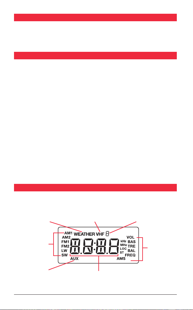
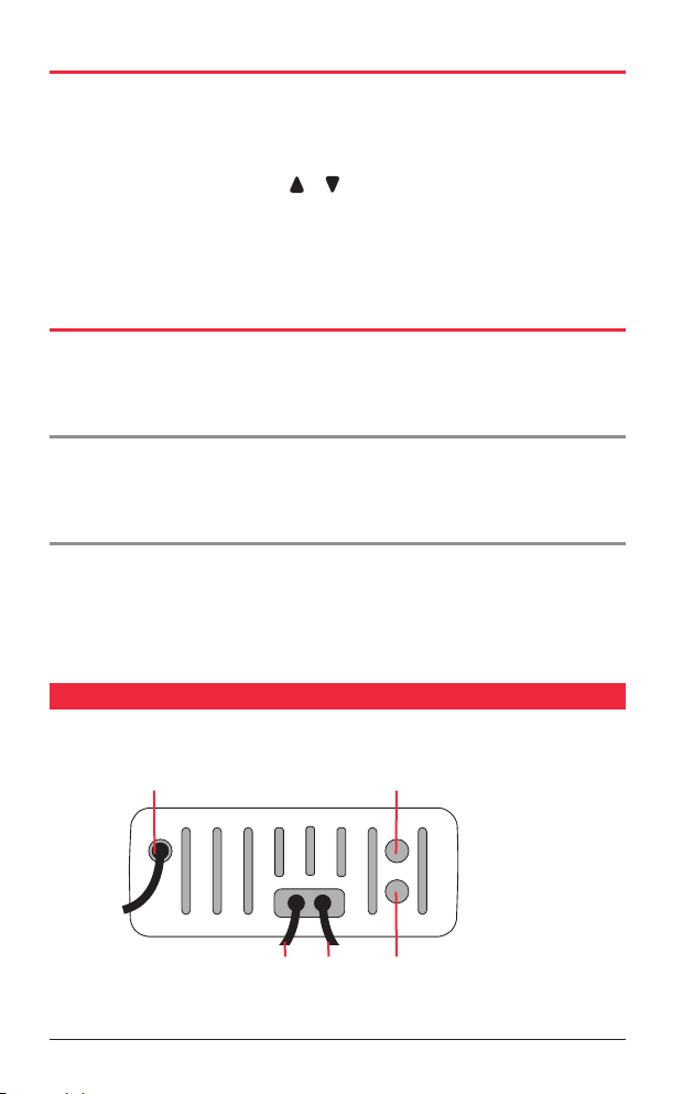
The GR200 has 7 selectable frequency bands plus an Auxiliary audio input. The frequency
bands available are Long Wave (LW), Short Wave (SW), Medium Wave (AM1 and AM2),
FM (FM1 and FM2) and VHF Marine (VHF). The Auxiliary input mode allows audio from
external sources such as MP3 players to be connected via a 3.5 mm socket lead on the
rear panel.
To select the desired frequency band (or the Auxiliary input) briefly press the Band key.
Each press will advance to the next band in the sequence and the corresponding symbol
LW, SW, AUX, AM1, AM2, FM1, FM2 or VHF will appear on the display to confirm your
selection. Note that when the AUX input is selected, ‘In’ will also be displayed when an
external device is connected.
The frequency coverage of each band is listed in the specifications on page 14 of this
manual. For information on the ‘AUX’ selection please see ‘Auxiliary Input’ on page 13.
Selecting USA or European Receiver Standards
The GR200 supports USA, Canadian and European standards for AM and FM reception.
Australian models conform to the European standard and are set that way by default.
Owners in the USA or Canada should select the USA or Canadian standard.
To switch between the standards, press and hold the Band key for 3 seconds. The GR200
will display ‘E’ at the top of the display for European, ‘U’ for USA or ‘C’ for Canada. The
‘E’, ‘U’ or ‘C’ symbols will disappear once any of the memory preset buttons are pressed.
The differences between the European, USA and Canadian bands are listed in the
specifications on page 14 of this manual.
Note: When the VHF marine band is selected, switching between USA, Canadian and
European standards will also select USA , Canadian or International VHF marine
channel allocations.
Manually Tuning the Frequency
Briefly press the Mode key repeatedly until ‘FREQ’ is displayed on the right hand side
of the LCD. You can now manually change the frequency. To adjust the frequency, briefly
press the or key. Pressing the key will increase the frequency while pressing the
Key will decrease the frequency. The frequency will be displayed on the LCD.
Scanning for Stations
While in frequency tuning mode, press and hold the or key for 3 seconds. The
GR200 will automatically scan upwards or downwards in frequency starting at the
present frequency. When a station is found, scanning will stop on that frequency.
Note: When tuning in the VHF band, standard VHF marine channel numbers 1-28 and 60-88
are displayed. If the USA or Canadian standard is selected, an additional ten NOAA weather
channels are also available. When these are selected, ‘WEATHER’ is displayed on the LCD.