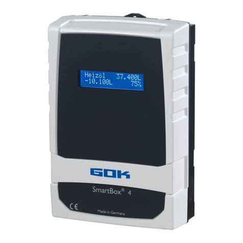
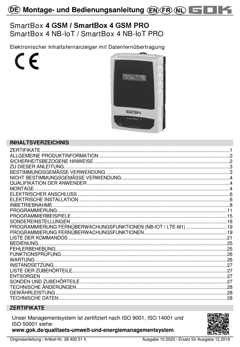
GOK SmartBox 4 LAN User instructions

Translation of the original operating instructions / part no. 28 410 57 b Version 12.2019 / Replaces version 12.2017
Assembly and operating manual
SmartBox®4 LAN / SmartBox®4 LAN PRO
Electronic remote level gauge with network connection
CERTIFICATE
Our management system is certified according to ISO 9001, ISO 14001 and
ISO 50001, see:
www.gok.de/qualitaets-umwelt-und-energiemanagementsystem.
CONTENTS
CERTIFICATE.......................................................................................................................................... 1
GENERAL PRODUCT INFORMATION .................................................................................................... 2
SAFETY ADVICE..................................................................................................................................... 2
WARRANTY ............................................................................................................................................ 2
ABOUT THE MANUAL............................................................................................................................. 3
INTENDED USE ...................................................................................................................................... 3
INAPPROPRIATE USE............................................................................................................................ 4
USER QUALIFICATION ........................................................................................................................... 4
ASSEMBLY.............................................................................................................................................. 4
ELECTRIC CONNECTION....................................................................................................................... 6
NETWORK CONNECTION ...................................................................................................................... 6
ELECTRICAL INSTALLATION ................................................................................................................. 6
START-UP ............................................................................................................................................... 8
TECHNICAL CHANGES ........................................................................................................................ 10
PROGRAMMING ................................................................................................................................... 10
EXAMPLES FOR PROGRAMMING ....................................................................................................... 14
NOTES ON PROGRAMMING ................................................................................................................ 16
CONFIGURING THE NETWORK COMMUNICATION ........................................................................... 19
OPERATION.......................................................................................................................................... 25
FUNCTION CHECK / MAINTENANCE................................................................................................... 26
DISPOSAL ............................................................................................................................................. 26
RESTORATION ..................................................................................................................................... 26
TROUBLESHOOTING ........................................................................................................................... 26
PROBES AND ACCESSORY PARTS .................................................................................................... 27
LIST OF ACCESSORIES ....................................................................................................................... 28
TECHNICAL DATA ................................................................................................................................ 28

SmartBox®4 LAN / SmartBox®4 LAN PRO
2 / 28 part no. 28 410 57 b
GENERAL PRODUCT INFORMATION
The electronic tank management system SmartBox®4 LAN, SmartBox®4 LAN PRO can be
used for remote monitoring of the level in unpressurised tanks containing liquids.
In addition to recording the tank content and remote data transfer, other functions can be
implemented by system enhancements, e. g. temperature measurement, reporting system
faults or connection to master control systems of the building.
The SmartBox®4 LAN has relay control functions, e. g. for activating external alarm devices,
solenoid valves, or the dry-run protection of pumps.
Via an integrated interface, a maximum of three more level gauges indicators
SmartBox®1, 2 or 3 can be connected and their measurements monitored remotely.
SmartBox®4 LAN PRO allows the content of up to four tanks to be recorded and monitored
remotely.
Because of its modular design, the system can be modified to suit many different applications.
The indicated measurements are not calibrated for invoicing.
SmartBox®4 LAN has a 2-line LCD display, a measuring input for connecting the probe, a
programmable relay with make and break switching output, a fault message input and an
integrated network connection for remote data transmission.
SmartBox®4 LAN PRO has a 2-line LCD display, four measuring inputs to connect the
probes, a fault message input and an integrated network connection for remote data
transmission.
SAFETY ADVICE
Your safety and the safety of others are very important to us. We have provided many
important safety messages in this assembly and operating manual.
Always read and obey all safety messages.
This is the safety alert symbol.
This symbol alerts you to potential hazards that can kill or hurt you and others.
All safety messages will follow the safety alert symbol and either the word
“DANGER”, “WARNING”, or “CAUTION”. These words mean:
describes a personal hazard with a high degree of risk.
May result in death or serious injury.
describes a personal hazard with a medium degree of risk.
May result in death or serious injury.
describes a personal hazard with a low degree of risk.
May result in minor or moderate injury.
describes material damage.
Has an effect on ongoing operation.
describes a piece of information
describes a call to action
WARRANTY
We guarantee that the product will function as intended and will not leak during
the legally specified period. The scope of our warranty is based on Section 8 of
our terms and conditions of delivery and payment.

SmartBox®4 LAN / SmartBox®4 LAN PRO
part no. 28 410 57 b 3 / 28
ABOUT THE MANUAL
•This manual is part of the product.
•This manual must be observed and handed over to the operator to ensure that
the component operates as intended and to comply with the warranty terms.
•Keep it in a safe place while you are using the product.
•In addition to this manual, please also observe national regulations, laws and
installation guidelines.
This assembly and operating manual is aimed at users and operators of this
product. These persons must have read and understood the assembly and operating
manual. The physical and psychical requirements for proper and safe handling of the
product must be ensured at all times!
INTENDED USE
Operating media
Operating media with consideration of the otherwise suitable probe type and accessories,
see:
Please comply with the “Level gauge type FSA-W 4-20mA for SmartBox®
1 – 4” assembly and operating manual!
Comply with the “Level probe” assembly and operating manual!
You will find a list of operating media with descriptions, the relevant
standards and the country in which they are used in the Internet at
www.gok.de/liste-der-betriebsmedien.
Escaping, liquid operating media:
•are hazardous to the aquatic environment
•are inflammable category 1, 2 or 3 liquids
•can ignite and cause burning
•can cause injury through people falling or slipping
Capture operating media during maintenance work.
Installation location
•with type of protection IP30, in protected and dry rooms
May not be used in potentially explosive areas.
Can cause an explosion or serious injuries.
Must be installed by a specialised company in accordance with local industrial
health and safety regulations.
Installation outside the defined EX protection zone.
Malfunctions caused by flooding!
The product is not designed for installation in areas prone to flooding or risk
areas.
Following flooding, the product must be replaced!

SmartBox®4 LAN / SmartBox®4 LAN PRO
4 / 28 part no. 28 410 57 b
INAPPROPRIATE USE
All uses exceeding the concept of intended use:
Display unit:
•changes to the product or parts of the product
•installation in a potentially explosive area
Probe:
•e.g. operation with different operating media
•operation with inflammable operating media of categories 1, 2 or 3 with a flash point
<55°C1)
•installation in pressurised tanks and containers
1) It is also necessary to comply with the divergent provisions/regulations of the EU member
states concerning areas at risk of explosion and the flash point of the operating medium!
USER QUALIFICATION
This product may be installed only by qualified experts. These are personnel who are familiar
with setting up, installing, starting up, operating and maintaining this product.
"Equipment and systems requiring supervision may be operated only by persons aged at
least 18, who are physically capable and who have the necessary specialist knowledge or
who have been instructed by a competent person. Instruction at regular intervals, but at least
once per year, is recommended."
Activity
Qualification
storing, transporting, unpacking, OPERATION
trained personnel
ASSEMBLY, MAINTENANCE
START-UP, SHUT-DOWN , REPLACEMENT,
RESTART, RESTORATION, DISPOSAL,
qualified personnel, customer service
ELECTRICAL INSTALLATION
qualified electrician
ASSEMBLY
Before assembly, check that the product is complete and has not suffered
any damage during transport.
ASSEMBLY must be carried out by a specialised company.
The specialised company and the operator must observe, comply with and understand all of
the following instructions in this assembly and operating manual. For the system to function
as intended, it must be installed professionally in compliance with the technical rules
applicable to the planning, construction and operation of the entire system.
These regulations also include the accident prevention regulations of the employers’ liability
insurance associations, the VDE regulations, and the installation and operating instructions.
The housing of the display unit is suitable for wall mounting and is connected to
the 230 V mains supply. Under normal circumstances, the display unit must be operated with
the housing cover closed.
It is installed and started up by a qualified technician while the unit is open.
Do not use this device for safety applications or emergency stop mechanisms
or misuse it!
Injuries and damage to health and property through misuse.
You must observe the information contained in these instructions, especially
regarding installation, start-up and maintenance.

SmartBox®4 LAN / SmartBox®4 LAN PRO
part no. 28 410 57 b 5 / 28
Damaged or destroyed insulation!
Can result in short circuit or electric shock.
Do not use the device if the insulation is damaged!
Have new insulation installed by a specialised company!
Selecting the installation location
Before installing the SmartBox®, you have to check whether a free network connection is
available at the intended installation location (see page configuring the network
communication / device connection in the network / LAN).
Installation of the display unit
Mount the display unit to the wall in a suitable position.
1. Open the display unit by removing the bottom cover.
2. After loosening the 2 screws, open the display unit by removing the cover.
3. Mount the display unit to a smooth vertical wall by means of dowels. Mount the housing
of the display unit by the four fixing holes with the enclosed screws and anchors.
Take care not to damage the housing.
4. After connecting the terminals and setting the unit up, replace the covers.
Installing the level probe
See assembly and operating instruction “Level probe“.
Installing the probe
See assembly and operating instruction
„FSA-W 4-20mA level gauge for SmartBox®1 – 4“.
1.
2.

SmartBox®4 LAN / SmartBox®4 LAN PRO
6 / 28 part no. 28 410 57 b
ELECTRICAL INSTALLATION see corresponding instruction
„FSA-W 4-20mA level gauge for SmartBox®1 – 4“.
ELECTRIC CONNECTION
Safety precautions for electrical components
The functions and operating safety of the device are guaranteed only under the
climatic conditions that are specified in TECHNICAL DATA. If the device is transported from a
cold to a warm environment, condensation may cause the device to malfunction or may even
destroy the device. Because of this, you must ensure that the device has acclimatised to the
ambient temperature before using it.
If you have any doubts that the device can be operated safely, do not operate it.
Your safety may be adversely affected by the device, if for example:
•it is obviously damaged
•it no longer works as specified
•it has been stored in unsuitable conditions for some time,
if in doubt, send the device to the manufacturer for repair or maintenance
Connection line between display unit and probe
Voltage
probe supply 20V DC
Connection
probe connection cable
+
–
SmartBox®4 LAN
probe - terminals
1
2
Tank 1 Fig.
SmartBox®4
LAN PRO
probe 1 - terminals
3
4
Tank 1 Fig
probe 2 - terminals
5
6
Tank 2
probe 3 - terminals
7
8
Tank 3
probe 4 - terminals
9
10
Tank 4
NETWORK CONNECTION
The network connection socket (RJ45) can be found in
the device (see figure and ). The network cable
(performance class cat 5 or higher) must be guided
through the left upper cable inlet into the housing.
Remove the cable inlet and insert the cable through the
slot in the cable inlet. Then, connect the network cable to
the device and press the cable inlet down until flush.
ELECTRICAL INSTALLATION
SmartBox®4 LAN PRO
SmartBox®4 LAN
Connection of supply voltage: Voltage: 230 V AC 50 Hz
Connection: Terminals PE + N+ Lto the display unit (cable not included in the delivery)

SmartBox®4 LAN / SmartBox®4 LAN PRO
part no. 28 410 57 b 7 / 28
Connection of relay contacts on the display unit SmartBox®4 LAN
The display unit SmartBox®4 LAN has two relay contact pairs for the connection of external
control circuits or for activating external alarm or signal devices. In case of failure of the unit
and if the fill level (and optionally temperature) is above the selected limit, the contacts of
relay terminals 7 + 8 are closed, or 9 + 10 are open - see PCB in the display unit.
SmartBox®4 LAN
Switching contact
normally closed (NC)
normally open (NO)
Relay
Terminals 7 + 8
Terminals 9 + 10
Switching voltage: max. 250V AC
Switching current: max. 3,5A
Excess voltage!
Damage to components and device defect.
No 230V AC connections may be made to terminals 3+ 4 and 5 + 6and probe input
terminals 1+ 2!
Conncetion of the interface SmartBox®4 LAN to SmartBox®1, 2 or 3
Via the integrated interface “SERIAL LINK INPUT“ terminals (3 + 4), a maximum of three
additional display unit SmartBox®1, 2 or 3 can be connected and the measured values for the
additional tanks (tank 2 to tank 4) can be monitored remotely.
For SmartBox®1, SmartBox®2 or SmartBox® 3, the two-pole output terminal “Serial Link
Output“ terminals (3 + 4) is connected to terminals 3 + 4 (terminal 3 3 and 4 4) of the
SmartBox®4 LAN with a two-core cable (e. g. 2 x 0.4mm²).
If the tanks should be numbered in a defined sequence (tank 2 to 4), then SmartBox®4 LAN
must be activated first, followed by the other display unit in the desired sequence.

SmartBox®4 LAN / SmartBox®4 LAN PRO
8 / 28 part no. 28 410 57 b
SmartBox®4 LAN PRO
Excess voltage!
Damage to components and device defect.
No 230 V AC connections may be made to probe input terminals 3 + 4, 5 + 6, 7 + 8 and
9 + 10 and terminals 1+ 2!
Connection of the fault signal input
A switch contact (make or break contact) can be connected to the fault message input; for a
burner fault signal, for example. If a fault occurs, an alarm is indicated at the display (with an
approx. 5-minute delay).
SmartBox®4 LAN
Terminal 5 + 6 “DIGITAL INPUT“
SmartBox®4 LAN PRO
Terminal 1 + 2 “ALARM INPUT“
START-UP
Operation elements and display
The device is adjusted once when it is put into operation. After start-up the device operates in
display mode with the top closed.
The display is a two-line LCD display with 2 x 16 characters.
The display has blue background lighting for best readability in all lighting conditions.
SmartBox®4 LAN has the following display:
The device is adjusted via the three small
blue buttons:
These are located on the
PCB between the
terminals.
Choose the language (German, English,
French or Spanish) in menu step 18.
Language+Names.
Liquid L
Fillspace L %

SmartBox®4 LAN / SmartBox®4 LAN PRO
part no. 28 410 57 b 9 / 28
After the contents the display unit has been installed, it can be started up.
Activating power supply:
Keep away from the area of the 230V terminal!
Activate power supply – the following is displayed
Fuel oil tank - wiring example SmartBox®4 LAN
Fuel oil tank - wiring example SmartBox®4 LAN PRO
Heat oil 0L
-
0L 100%
Oil tank
Level probe
Oil tank
Level
probe

SmartBox®4 LAN / SmartBox®4 LAN PRO
10 / 28 part no. 28 410 57 b
Rain water tank - wiring example SmartBox®4 LAN
TECHNICAL CHANGES
All the information contained in this assembly and operating manual is the result of product
testing and corresponds to the level of knowledge at the time of testing and the relevant
legislation and standards at the time of issue. We reserve the right to make technical changes
without prior notice. Errors and omissions excepted. All figures are for illustration purposes
only and may differ from actual designs.
PROGRAMMING
Overfilling of the tank due to incorrect entry values.
Operating media may leak. These:
•are hazardous to water,
•are category 1,2 and 3 inflammable liquids,
•can ignite and cause burning,
•may cause falling injuries due to slipping.
Enter these values with care!
The entry values are also retained in the event of the failure of the supply voltage.
Programming the level gauge
Before programming, you need to ascertain the tank data and enter the values into the right
column (Input value) of the following table. Then, enter the values for the individual entry
steps.
Water for domestic use
Level
probe
Relay 1:
7
- 8 = break contact
=> pump safe to run dry
Relay 2:
9
-10 = make contact
=> automatic backfeed
control system
Storm water reservoir
Feed pump
Drinking water network
Solenoid valve for backfeed
Optional
switch

SmartBox®4 LAN / SmartBox®4 LAN PRO
part no. 28 410 57 b 11 / 28
Setting a
parameter:
Press [ENTER] to open setup mode.
Select the desired setting parameter via [PLUS].
Press [ENTER] to call up the value selection for the parameter.
Set the value with [MINUS]/[PLUS], press [ENTER] to save.
Quitting the
setup mode:
You can quit the setup mode at any time. Select “Exit“ and press
[ENTER] to go back to the standard display mode.
Menu
Input function
Input value
Tank: 1
SmartBox 4
LAN PRO
Select the tank (tank: 1 to tank: 4) to enter the
corresponding values. (This step is not displayed if
only one probe is connected to SmartBox®4 LAN
PRO.)
Tank:_______
Tank:_______
Tank:_______
Tank:_______
0.Exit
Press [ENTER] to return to display mode
1.Measure
probe
Select probe measuring range see type label of the
probe - default setting 250 mbar
________mbar
Standard probe
max. tank height for
fuel oil
water
100mbar
1.20m
1.00m
150mbar
1.80m
1.50m
160mbar
1.90m
1.60m
200mbar
2.40m
2.00m
250mbar
2.90m
2.50m
400mbar
4.70m
4.00m
500mbar
6.00m
5.00m
1.000mbar
12.00m
10.00m
2.000mbar
24.00m
20.00m
3.000mbar
36.00m
30.00m
5.000mbar
60.00m
50.00m
set mbar
2.Liquid
Select the medium
_______kg/m³
If the density of
the stored
medium is
unknown, the
reference
height can be
entered in
menu item
“10.Trim
height”
Medium
Density value kg/m³
(15 °C)
Heat oil
845kg/m³ - default setting
Water
999kg/m³
Diesel
830kg/m³
Biodiesel
880kg/m³
RME, FAME
880kg/m³
Rape oil
915kg/m³
Palm oil
910kg/m³
Motor oil
865kg/m³
AdBlue
1090kg/m³
Regular gasoline
743kg/m³
Premium gasoline
750kg/m³
Density value
Enter a special density value

SmartBox®4 LAN / SmartBox®4 LAN PRO
12 / 28 part no. 28 410 57 b
Menu
Input function
Input value
3.Tank shape
Select Tank shape with [Enter]
Linear
Default setting
linear tank, rectangular tanks, vertical cylinders,
basement-welded steel tanks.
Cylinder
horizontal
cylindrical tank with arched ends
horizontal tanks, tubular tanks
typical shape for steel outdoor or buried tanks.
Ball-shaped
spherical tank; buried tanks with spherical
basic shape; frequently plastic buried tank (GRP).
Oval
oval basement tanks; typical shape of GRP
tanks and single-walled sheet metal tanks
Convex
Plastic battery tanks, convex,
slightly convex shape, alternative to linear
Concave
Plastic battery tanks, concave,
slightly concave shape, alternative to linear
Holed
plastic
Plastic tank with recess
Plastic tank with a large recess (hollow) in the center
(without tape bindings)
Tube w.
flat ends
Lying cylindrical tank with flat ends,
tube segment with straight end plates.
Typical tank shape for smaller diesel tanks.
Metal oil
tanks
Plate tank or plate tank battery
linear side walls, with semicircular arc top and bottom.
Bearing
chart
Enter a special tank shape from existing bearing chart.
For this purpose, up to 16 value pairs (height in cm +
volume in L) can be entered.
Before the value pairs are entered, the values for the
tank volumes must be entered in in steps "4.Tank
volume" and "5. Internal tank height".
Index: 0
0cm
0L
Index: 1 xxx.x cm xxxx L
Index: 2 . cm L
Index: 3 . cm L
max.
Index:16max. cm max. L
Specified value pair (do not have to be entered).
first value pair entered
max. inside height of tank
the max. tank volume menu
step “5.Internal tank height” is allocated automatically
and does not have to be entered.
Not all 15 intermediate value pairs (Index: 1 - 15) have to be entered.
A linear interpolation is made between 2 interpolation values. For a linear range of the tank
geometry it is sufficient to enter a lower and an upper value pair.

SmartBox®4 LAN / SmartBox®4 LAN PRO
part no. 28 410 57 b 13 / 28
Menu
Input function
Input value
4.Tank
volume
Adjust the tank volume with [+] / [-] (100%). The default
setting is 0 L. The value must be set.
___________L
Please see a volume table for the highest value,
if available. For a 100 m³ cyl. buried tank, this
may for example be the value 100600 litres.
5.Tank
height
Enter inner tank height in millimetres: e. g.: 249 cm
(max. value = 999,9 cm) (height without dome)
_________mm
Please see a volume table for the highest value,
if available. For a 100 m³ cyl. buried tank, this
may for example be the value 288 cm.
5b.Filling
limit
Set the filling limit of the tank with [+]/ [-]:
With fuel oil tanks, that is the shut-off point of the limit
indicator. The default setting is 95%.
e.g. 95%=237cm. For tanks which can be filled to the
very top (e.g. water tanks), it is necessary to set the
highest value of 99%.
__________%
6.View
SmartBox
4 LAN
In the 1st line of the display, the tank name/medium and
contents are displayed (e.g. in litres).
The display in the 2nd line can be selected:
____________
View details
e.g.
Single/detailed
Fillspace+Percent
a)
Fillspace+Level
b)
Percent+Level
c)
For fuel oil tanks in Germany, a free capacity display is
required according to TRwS 791-2. This is possible with
selection a) and b).
6.View
Tanks
SmartBox
4 LAN PRO
Single/Detailed
The tanks are displayed
cyclically one after the other, with L, % and, if
applicable, temperature. With display change.
Collective
The (eg. L) values of tanks 1 to 4 are displayed
(depending on the number of connected probes)
Without display change.
Percent
Yes
No
Select Yes
display change
values (eg. in L) Tank 1 – 4
total capacity display + percent values
Entering incorrect switching points and mixing up the switch-on and shut-off
point can lead to the overfilling of the tank or the dry running of a pump!
7.Relay 1
SmartBox
4
Switch function relay:
Deactive
The relay does not switch.
Active
The relay switches .
On
Forces the relay to energise.
Off
Forces the relay to de-energise.

SmartBox®4 LAN / SmartBox®4 LAN PRO
14 / 28 part no. 28 410 57 b
Example of switch point setting for Active (with
hysteresis):
Enter switching points as % values from 01 - 99 (and/or
enter as °C value from -99 to +99 only for probe with
temperature measurement)
deactive activate with [+] / [-] to
active press [Enter] to confirm
On 10% ON: set with [+] / [-] [Enter]
Off 12% OFF: set with [+] / [-] [Enter]
On +0°C ON: set with [+] / [-] [Enter]
Off +0°C OFF: set with [+] / [-] [Enter]
Deactivate the relay via deactive or input of 0% or
0°C (for On and Off).
ON ______%
OFF ______%
ON ______°C
OFF ______°C
7.Exit
SmartBox 4 PRO Press [Enter] to return to display mode
8.Exit Press [Enter] to return to display mode
After performing entry steps 1 - 7, the programming process is completed.
After confirmation of step “8.Exit“, the device automatically returns to default display mode;
the current tank content is shown in the display.
Special functions are available under entry steps 9 to 24.
After the end of setup, do not forget to replace the housing cover!
After completing the ASSEMBLY and PROGRAMMING, carrying out a function check is
recommended (FUNCTION CHECK section).
EXAMPLES FOR PROGRAMMING
Example 1: Basement tank for 6.000 litres fuel oil, litre display, linear steel tank
Inner height 165cm, (fill level 125cm)
SmartBox®4 LAN with standard probe 0 - 250mbar
Step
Entries / selection
1.Measure probe
250mbar
2.Liquid
Heat.oil
3.Tank shape
Linear
4.Tank volume
6.000L (set with [+] / [-] keys)
5.Tank height
165.0cm (set with [+] / [-] keys)
5b.Filling limit
95%=157cm (set with [+] / [-] keys)
6.View View details
Fillspace+Percnt
display 2. line - (set with [+] / [-] keys)
7.Relay
Deactive
8.Exit press [+] to go to
15.Network
DHCP: Yes
16.-18.
press [+] to go to
19.Exit
press [Enter] to see the indication
Heat.oil 4.550L
-1.150L 76%

SmartBox®4 LAN / SmartBox®4 LAN PRO
part no. 28 410 57 b 15 / 28
Example 2: Buried tank, cylindrical, horizontal, for 100.600 litres diesel oil
Inner height 288.6cm, (fill level 54cm)
SmartBox®4 LAN with 4 standard probes 0 - 250mbar
The relay is to be used as an dry-run protection for a pump.
Relay - On at > 11% - Off at < 10%
Step
Entries / selection
1.Measure probe
250mbar
2.Liquid
Diesel (set with [+] / [-] keys)
3.Tank shape
Cyl.horizontal (set with [+] / [-] keys)
4.Tank volume
100.600L (exact value from volume table,
set with [+] / [-] keys)
5.Tank height
288.6cm (exact value from volume table,
set with [+] / [-] keys)
5b.Filling limit
97%=279cm (set with [+] / [-] keys)
6.View View details
Fillspace+Percnt
display 2. line - (set with [+] / [-] keys)
7.Relay Active Limiting
tank:1
Switch-on: 11% Switch-off: 10%
(set with [+] / [-] keys)
8.Exit
press [+] to go to
15.Network
DHCP: Yes
16.-18. press [+] to go to
19.Exit
press [Enter] to see the indication
Diesel 12.800L
-84.800L 13%
Example 3: 4 Basement tanks for 15.000 litres fuel oil, litre display, linear steel tank
Inner height 220cm, (fill level tank 1 = 125cm)
SmartBox®4 LAN PRO with 4 standard probes 0 - 250mbar
connection to Smart-Inspector-database
Step
Entries / selection
Tank number:
1 (2,3,4)
1.Measure probe
250mbar
2.Liquid
Heat.oil
3.Tank shape
Linear
4.Tank volume
15.000L (set with [+] / [-] keys)
5.Tank height
220.0cm (set with [+] / [-] keys)
5b.Filling limit
95%=209cm (set with [+] / [-] keys)
6.View tanks
Single/detailed
Collective
Percents: Yes
(L
Σ
% are displayed alternately)
7.Exit press [+] to go to
15.Network
DHCP: Yes Destination
SmartInspector
16.-18.
press [+] to go to
19.Exit
press [Enter] to see the indication
8.500L 8.520L
Σ34.120L
8.540L 8.560L 57% 57% 57% 57%
For Tank 2-4 repeat the entry with the correct value in the same way as with tank1

SmartBox®4 LAN / SmartBox®4 LAN PRO
16 / 28 part no. 28 410 57 b
Tanks with inner shell
For tanks with an inner shell (e.g. cylindrical horizontal or tanks welded together in the
basement) the data in steps "4.Tank volume" and "5.Internal tank height" must be corrected.
Examples:
Wall thickness of inner casing 0.5cm reduce value for inner height by approx. 1cm,
reduce volume for 10m³ by 1.3%, for 20m³ by 1 %, for 50m³ by 0.8% and for 100m³
by 0.7 %.
Wall thickness of inner casing 2cm reduce value for inner height by approx. 4cm,
reduce volume for 10m³ by 5%, for 20m³ by 4%, for 50m³ by 3% and for 100m³ by 2.5%.
NOTES ON PROGRAMMING
Menu
Setting
Description
9.Offset
probe
Adjusting:
•Probe zero point, electric
•Position / Distance from base
•Unusable capacity that is not to be displayed
ESC
Exit the menu
Offset calibr.
New measurement of probe zero point (electric).
Lift level probe out of the liquid beforehand.
Probe bottom
gap
Probe pos: x cm;
normal reference is x = 0cm, max = 99cm
Bottom
deadstock
Sucker pos: y cm
Normal reference is 0cm = complete capacity.
y > 0cm means corresponding unusable capacity.
Default values
Reset values from menu step 9 to factory settings.
10.Trim
height
xxx.x cm
Entry option for the reference height for the 2-point
measurement, for other probe measurement range
or for an unknown density. Subtract 1.0cm from the
actual measured level and enter this value.
Calibrate:No
Calibrate:Yes
If activated (Yes), the display in menu steps
“1.Measure probe” and “2.Liquid” is then "by
Calibration". If this is entered with an
almost empty tank, it is recommended that you
make a correction the next time it is filled.
11.Exit
Press [Enter] to return to display mode
12.Unit
Ldefault settings
m³
%
m
kg
IG
UG
t
mbar
kPa
litre:
cubic meters:
percent:
meter:
kilogram:
imperial Gallon:
US liquid gallon:
ton:
millibar:
kilopascals:
999900L
2.50m³
99.50%
2.50m
999900kg
219750IG
263900UG
2.50t
500mbar
50kPa

SmartBox®4 LAN / SmartBox®4 LAN PRO
part no. 28 410 57 b 17 / 28
Menu
Setting
Description
13.Rounding
Automatically
non rounded
20L
50L
100L
200L
500L
1.000L
Default settings:
minimal increments
Rounding increments in relation to the set volume
set with [+] / [-] keys
14.Exit
Press [Enter] to return to display mode
15.Network
DHCP: YES
DHCP: NO
Select whether to automatically obtain the IP
address or directly specify it.
Detailed description of all the adjustable parameters look at
CONFIGURING THE NETWORK COMMUNICATION.
16.Sort
tanks
with
SmartBox 4
LAN
ESC
Exit the menu
Delete Tank n
Delete the registered Tank
T2<->T3
Replace Tank 2 for Tank 3
T2<->T4
Replace Tank 2 for Tank 4
T3<->T4
Replace Tank 3 for Tank 4
16. Delete
tank
with
SmartBox 4
LAN PRO
ESC
Exit the menu
Delete Tank n
Settings for tank n are deleted and reset to default
settings (tanks 2, 3, 4)
17.Input/
Output
Alarm-In:
Sets the function of the alarm contact input
Closing
Closer alarm. Input closed Alarm
Opening
Opener alarm. Input contact opens Alarm
Deactiv
Sets the alarm input functionless
Data-Out:
Defines the data output on the output adapter slot
Tank: 1
Tank: 1-4
For data output a selection can be made between
•Output single tank 1, 2, 3 or 4 for analogue
adapter
•Output “1-4” all tanks are output sequentially
via digital slot-in adapter – e.g. for H-Box
17b.
H protocol
Data output:
Deactiv
Data: Litres
Data: Level
Data output to H Box (only with DTM-2):
•Deactivated
•Output in litres
•Output in level
18.Language
Language:
German, English, French, Spanish
[+] / [-] / [Enter]
Names:
ESC [+] / [-] / [Enter]
Name Tank 1: Suggested name
Letters can be changed with [+] / [-] / [Enter]
19.Exit
Back to display mode

SmartBox®4 LAN / SmartBox®4 LAN PRO
18 / 28 part no. 28 410 57 b
Menu
Setting
Description
20.LCD
display
Contrast: 90
Set the contrast of the LCD display
21.Device
info
Software version:V7.00 (e. g.)
Serial number: Tank 1: SN=1234 (e. g.)
Offset+Gain:X0=4.05mA B=1268 (Tank 1)
22.Test
current
Test function for the current mA value of the probe:
ADC: 7400=11.40 mA
If level probe is not submerged, the value should
be close to 4 mA. Tolerance range is 3.7 ... 4.3mA.
23.Test
relay
SmartBox 4
Furthermore, devices connected on the relay contact will
also be switched on and/or off!
•Connected devices can be damaged (dry running).
•Operating media may leak.
Disconnect the devices connected before test relay.
Only reconnect the devices again after test relay.
Relay 1 ON/OFF
Test function for the switch function of relay
24.Reset
ESC
Reset the device software:
Exit this function without executing it.
Restart
Initialization. The device software restarts and
keeps all device settings.
Factory
settings
Complete reset of all parameters to the original
delivery status.
Reset password
Password resetting to default ‘tank‘.
26.Exit
Press [Enter] to return to display mode
SmartBox®4 LAN
-Activation of other indicators (and assignation of the respective tank numbers)
Numbering the tanks (if applicable)
The level gauge SmartBox®4 LAN always has tank number 1.
If other level gauge SmartBox®1, 2 or 3 (display unit) are to be connected, they must be
assigned defined tank numbers. The tank numbers are simply assigned in the sequence in
which the display units log on for the first time.
•First, activate display unit 2 for tank number 2 (switch on mains voltage), then for display
unit 3, and so on.
Example: Activate tank 2
•After connection the display unit of tank 2 as described under electrical installation –
Connecting the Interface to SmartBox®1, SmartBox®2 or SmartBox®3, switch on the
display unit of the tank in question (switch on the mains voltage).
In the display unit of SmartBox®4 LAN, the following will be indicated alternatingly: “Tank1:” -
“xx.xxxL“ – “Tank2:“ – “yy.yyyL“ (depending on the selection / adjustment in the menu step
6. Show tanks). Then, follow the same steps for the other display units.
The order of the displayed tanks can be changed subsequently under menu step
16.Sort. Tanks
SmartBox 4 LAN to be changed.

SmartBox®4 LAN / SmartBox®4 LAN PRO
part no. 28 410 57 b 19 / 28
CONFIGURING THE NETWORK COMMUNICATION
Network communication for the device is configured via the menu item "15.Network".
By default, DHCP is enabled with "Yes". In this case, the device is assigned its IP address,
subnet mask, gateway and DNS server address automatically by the router.
Alternatively you can/should configure these address parameters manually. To do this, select
"No" in DHCP. In particular, your network administrator should confirm the port no. for the
device.
When the network cable has been connected, the device can be addressed in the network
(LAN) with a browser. To do this, enter the IP address of the device, such as 192.168.0.112,
in the browser's address line.
It is generally advisable to involve the network administrator for these configuration settings.

SmartBox®4 LAN / SmartBox®4 LAN PRO
20 / 28 part no. 28 410 57 b
Overfilling of the tank due to incorrect entry values.
Operating media may leak. These:
•are hazardous to water,
•are category 1,2 and 3 inflammable liquids,
•can ignite and cause burning,
•may cause falling injuries due to slipping.
Enter these values with care!
The entry values are also retained in the event of the failure of the supply voltage.
Device connection in the network
The Ethernet network connection is established as follows:
Option A: Direct connection for testing
Connect a PC/laptop directly with SmartBox®4 LAN with a crossover cable
Option B: Mini network
Connect a PC/laptop with SmartBox®4 LAN via a switch or router
Option C: LAN/intranet
PC and SmartBox®4 LAN are connected directly to a local network (LAN/intranet). In each
case the SmartBox®4 LAN and the PC must be in the same network segment or be able to
"see" each other via corresponding routers
Other manuals for SmartBox 4 LAN
1
This manual suits for next models
1
Table of contents
Other GOK Measuring Instrument manuals

GOK
GOK BC-1 Series User instructions

GOK
GOK GWG User instructions

GOK
GOK SmartBox 1 User instructions

GOK
GOK SmartBox 1 User manual

GOK
GOK SmartBox 4 GSM User instructions

GOK
GOK BC-1-4 User instructions

GOK
GOK SmartBox 4 User instructions

GOK
GOK GWG User instructions

GOK
GOK GWG User instructions

GOK
GOK SmartBox 1 User manual