GOK EN61-DS PS User instructions

Originalanleitung / Artikel-Nr. 01 150 50 f Ausgabe 12.2022 / Ersatz für Ausgabe 02.2018
Montage- und Bedienungsanleitung
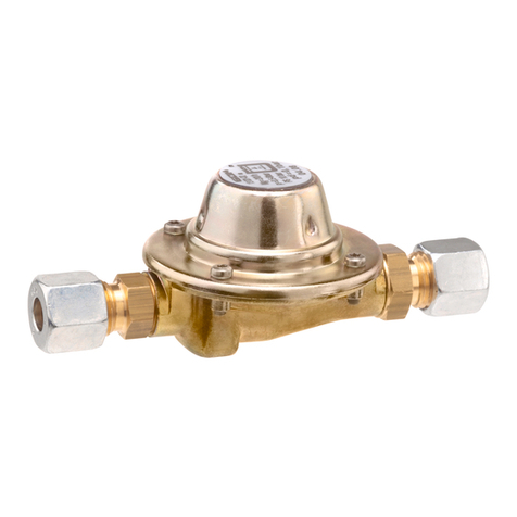
Niederdruckregler Typ EN61-DS PS 16 bar
zum direkten Anschluss an Gasflaschen
für Außenanlagen
für Innenanlagen
für Innenanlagen
INHALTSVERZEICHNIS
ZERTIFIKATE...........................................................................................................................................1
ZU DIESER ANLEITUNG..........................................................................................................................1
SICHERHEITSBEZOGENE HINWEISE....................................................................................................2
PRODUKTBEZOGENE SICHERHEITSHINWEISE...................................................................................2
ALLGEMEINE PRODUKTINFORMATION ................................................................................................2
BESTIMMUNGSGEMÄSSE VERWENDUNG ...........................................................................................2
NICHT BESTIMMUNGSGEMÄSSE VERWENDUNG................................................................................3
VORTEILE UND AUSSTATTUNG.............................................................................................................3
AUFBAU ...................................................................................................................................................4
ANSCHLÜSSE..........................................................................................................................................5
MONTAGE................................................................................................................................................6
DICHTHEITSKONTROLLE .......................................................................................................................7
INBETRIEBNAHME ..................................................................................................................................8
BEDIENUNG.............................................................................................................................................8
FEHLERBEHEBUNG................................................................................................................................8
WARTUNG ...............................................................................................................................................9
INSTANDSETZUNG .................................................................................................................................9
AUSSERBETRIEBNAHME .......................................................................................................................9
AUSTAUSCH............................................................................................................................................9
ENTSORGEN .........................................................................................................................................10
TECHNISCHE DATEN............................................................................................................................10
LISTE DER ZUBEHÖRTEILE..................................................................................................................10
GEWÄHRLEISTUNG..............................................................................................................................10
TECHNISCHE ÄNDERUNGEN...............................................................................................................10
ZERTIFIKATE
Unser Managementsystem ist zertifiziert nach ISO 9001, ISO 14001 und
ISO 50001 siehe:
www.gok.de/qualitaets-umwelt-und-energiemanagementsystem.
ZU DIESER ANLEITUNG
•Diese Anleitung ist ein Teil des Produktes.
•Für den bestimmungsgemäßen Betrieb und zur Einhaltung der Gewährleistung
ist diese Anleitung zu beachten und dem Betreiber auszuhändigen.
•Während der gesamten Benutzung aufbewahren.
•Zusätzlich zu dieser Anleitung sind die nationalen Vorschriften, Gesetze und
Installationsrichtlinien zu beachten.
EN61-DS PS 16 bar
2 / 50 Artikel-Nr. 01 150 50 f
SICHERHEITSBEZOGENE HINWEISE
Ihre Sicherheit und die Sicherheit anderer ist uns sehr wichtig. Wir haben viele wichtige
Sicherheitshinweise in dieser Montage- und Bedienungsanleitung zur Verfügung gestellt.
Lesen und beachten Sie alle Sicherheitshinweise sowie Hinweise.
Dies ist das Warnsymbol. Dieses Symbol warnt vor möglichen Gefahren, die den
Tod oder Verletzungen für Sie und andere zur Folge haben können. Alle
Sicherheitshinweise folgen dem Warnsymbol, auf dieses folgt entweder das Wort
„GEFAHR", „WARNUNG" oder „VORSICHT". Diese Worte bedeuten:
bezeichnet eine Personengefährdung mit einem hohen Risikograd.
Hat Tod oder eine schwere Verletzung zur Folge.
bezeichnet eine Personengefährdung mit einem mittleren Risikograd.
Hat Tod oder eine schwere Verletzung zur Folge.
bezeichnet eine Personengefährdung mit einem niedrigen Risikograd.
Hat eine geringfügige oder mäßige Verletzung zur Folge.
bezeichnet einen Sachschaden.
Hat eine Beeinflussung auf den laufenden Betrieb.
bezeichnet eine Information
bezeichnet eine
Handlungsaufforderung
PRODUKTBEZOGENE SICHERHEITSHINWEISE
Ausströmendes Flüssiggas (Kategorie 1):
•ist extrem entzündbar
•kann zu Explosionen führen
•schwere Verbrennungen bei direktem Hautkontakt
Verbindungen regelmäßig auf Dichtheit prüfen!
Bei Gasgeruch und UndichtheitFlüssiggasanlage sofort außer Betrieb nehmen!
Zündquellen oder elektrische Geräte außer Reichweite halten!
Entsprechende Gesetze und Verordnungen beachten!
ALLGEMEINE PRODUKTINFORMATION
Der Druckregler hält den auf dem Typschild angegebenen Ausgangsdruck konstant,
unabhängig von Schwankungen des Eingangsdruckes und Änderungen von Durchfluss und
Temperatur innerhalb festgelegter Grenzen.
BESTIMMUNGSGEMÄSSE VERWENDUNG
Betriebsmedien
•Flüssiggas (Gasphase)
Eine Liste der Betriebsmedien mit Angabe der Bezeichnung,
der Norm und des Verwendungslandes erhalten Sie im Internet unter
www.gok.de/liste-der-betriebsmedien.
Einbauort
•zum wahlweisen Anschluss an eine 5, 11 bzw. 33 kg Gasflasche

EN61-DS PS 16 bar
Artikel-Nr. 01 150 50 f 3 / 50
Einsatzbereich
•Haushalt •Gewerbe und Industrie
Bei Anwendung im privaten Bereich: TRF beachten. Bei Anwendung im
gewerblichen Bereich: DGUV Regel 110-010 (bis 2022 DGUV Vorschrift 79)
beachten. Nur Druckregler mit einem Ausgangsdruck von 50 mbar sind für den
Einsatz in Deutschland geeignet!
Anwendungsbeispiele:
Einflaschenanlage mit Kleinflasche im privaten / gewerblichen Bereich, Typ EN61-DS
Zweistufiger Sicherheitsdruckregler S2SR
(ÜDS), Sichtanzeige, Kontrollmanometer und
pd50mbar, für Haushalts- und
Gewerbeanlagen im Freien.
Entspricht der Klassifizierung F1 nach
DIN 4811.
Zweistufiger Sicherheitsdruckregler S2SR
(ÜDS), Sichtanzeige, Thermisch auslösende
Absperreinrichtung „T“ (TAE), Kontrollmano-
meter und pd50mbar für Haushalts- und
Gewerbeanlagen im Gebäude. Entspricht der
Klassifizierung F1-t nach DIN 4811.
NICHT BESTIMMUNGSGEMÄSSE VERWENDUNG
Jede Verwendung, die über die bestimmungsgemäße Verwendung hinausgeht:
•z. B. Betrieb mit anderen Betriebsmedien, Drücken
•Verwendung von Gasen in der Flüssigphase
•Einbau entgegen der Durchflussrichtung
•Betrieb mit nicht zulässigen Schlauchleitungen
•Änderungen am Produkt oder an einem Teil des Produktes
•Verwendung bei Umgebungstemperaturen abweichend von: siehe TECHNISCHE DATEN
VORTEILE UND AUSSTATTUNG
Zweistufiger Sicherheitsdruckregler S2SR (ÜDS)
Der Zweistufige Sicherheitsdruckregler S2SR („S2SR“ Safety two Stages Regulator) ist eine
Kombination aus zwei, in Reihe geschalteten, Druckreglern.
Der Zweistufige Sicherheitsdruckregler S2SR dient zur Absicherung der Verbrauchsgeräte
vor unzulässig hohem Druck. Wenn eine der beiden Reglerstufen ausfällt, z. B. durch
Schmutz bzw. andere Fremdkörper am Ventil, übernimmt die jeweils andere Reglerstufe eine
Druckreduzierung auf 100 oder 150 mbar.
Der Druckregler ist auf dem Typschild mit „S2SR“ gekennzeichnet.
Nach Inbetriebnahme des Druckreglers muss die Sichtanzeige GRÜN anzeigen.
Steigt der Ausgangsdruck über 80 mbar (Ausführungen mit Ausgangsdruck 29 bis 50 mbar),
schaltet die Sichtanzeige auf ROT. Siehe FEHLERBEHEBUNG.

EN61-DS PS 16 bar
4 / 50 Artikel-Nr. 01 150 50 f
Filtersieb im Eingangsanschluss des Druckreglers
Im Flüssiggas können Fremdkörper, z. B. Schmutz, enthalten sein. Diese werden ab einer
bestimmten Größe von dem Filtersieb im Eingangsanschluss gefiltert. Wird das Flüssiggas
nicht gefiltert, erhöht sich der Verschleiß der Flüssiggasanlage, bis hin zu deren Ausfall.
Siehe FEHLERBEHEBUNG.
Option Thermisch auslösende Absperreinrichtung „T“ (TAE)
Bei Temperaturen von 100 °C löst die thermische Absperreinrichtung „T“ (TAE), im Weiteren
„T“ (TAE) genannt, aus und sperrt selbsttätig die Gaszufuhr ab. Nach Ansprechen der TAE
muss das Produkt ausgetauscht werden. Der Druckregler ist auf dem Typschild mit „t“
gekennzeichnet.
Option Manometer
Das Produkt ist mit einem Manometer zur Anzeige des Eingangsdruckes ausgestattet. Das
Manometer kann zur Dichtheitskontrolle verwendet werden (siehe „Ausführung mit
Manometer“ unter DICHTHEITSKONTROLLE).
Option Strömungswächter EFV
Strömungswächter EFV - Excess Flow Valve
Bezeichnung nach EN 16129 für integrierte Schlauchbruchsicherung SBS
Der Strömungswächter EFV ist eine integrierte Sicherheitseinrichtung, die die Absperrung des
Gasdurchflusses bewirkt, wenn der Durchfluss > 110 % als der Sollwert des Druckreglers ist.
Dies kann z. B. durch einen Schlauch- oder Rohrleitungsbruch ausgelöst werden.
Die Wiederherstellung des Gasdurchflusses erfolgt durch manuellen Eingriff, wenn die
Bedingungen, die das Ansprechen der Sicherheitseinrichtung hervorgerufen haben, nicht
mehr gegeben sind. Die Wiederherstellung des Gasdurchflusses wird durch eine Hand
betätigte Einrichtung ermöglicht. Der Druckregler ist auf dem Typschild mit „EFV“
gekennzeichnet.
Die Inbetriebnahme des Strömungswächters EFV erfolgt durch Drücken des Bedienknopfes,
bis ein Druckausgleich stattfindet.
AUFBAU
Eingangsanschluss
Ausgangsanschluss
Manometer optional
Zweistufiger Sicherheitsdruckregler S2SR (ÜDS)
Sichtanzeige optional
Entlüftungsstopfen
Bedienknopf des integrierten
Strömungswächters EFV (SBS)
optional
Thermisch auslösende
Absperreinrichtung „T“ (TAE)
optional

EN61-DS PS 16 bar
Artikel-Nr. 01 150 50 f 5 / 50
ANSCHLÜSSE
Eingang wahlweise
Handelsname und Abmessung nach Norm
Montagehinweis
Kombinationsanschluss (Komb.A)
•mit Polyamid Dichtung
•G.5 = Gewinde W 21,8 x 1/14 LH
Schlüsselweite
SW 30
Sechskant
FR-Shell (Shell-F)
•Flügel weich mit Gummidichtung und
Überwurfmutter 5-Flügel
•G.2 = Gewinde 21,8 x 1/14-LH - 60°
Handfest anziehen!
Kleinflasche (KLF)
•mit Überwurfmutter 5-Flügel
•G.12 = Gewinde W 21,8 x 1/14-LH ÜM
Handfest anziehen!
Italienischer Anschluss (Ital.A)
•mit Gummidichtung und Überwurfmutter
•G.1 = Gewinde W 20 x 1/14 LH
Schlüsselweite
SW 25
Sechskant
Shell Kombi Weich (Komb.Shell-WS)
•X.2
•mit Dichtung und Überwurfmutter
•Gewinde W 21,8 x 1/14-LH
Schlüsselweite
SW 25
Sechskant
POL-Weich-Flügel (POL-WF)
•mit Gummidichtung und Flügelschraube
•G.10 = Gewinde 0,880-14 NGO-LH
Schlüsselweite
SW 24
Sechskant
Dichtungen in den Anschlüssen (sofern vorgesehen) müssen unbeschädigt sein und
richtig in der Fassung liegen.
Alternativ sind noch andere Anschlüsse möglich. Alle G. und H. Anschlüsse nach EN 16129.
Ausgang
wahlweise
Handelsname und Abmessung
nach Norm
Montagehinweis
Kugelnippelanschluss
•H.4 = Gewinde G 1/4-LH-KN
Drehmomente:
G 1/4 = 5-7 Nm
Schneidringverschraubung RVS
•H.9 = RVS 10
Einschraubverschraubung
•H.22 = IG G 1/4
•Zur Aufnahme einer
Einschraubverschraubung mit O-Ring.

EN61-DS PS 16 bar
6 / 50 Artikel-Nr. 01 150 50 f
MONTAGE
Vor der Montage ist das Produkt auf Transportschäden und Vollständigkeit zu prüfen.
Die MONTAGE kann vom Betreiber der Anlage vorgenommen werden!
Alle nachfolgenden Hinweise dieser Montage- und Bedienungsanleitung müssen vom
Fachbetrieb, Betreiber und Bediener beachtet, eingehalten und verstanden werden.
Voraussetzung für ein einwandfreies Funktionieren der Anlage ist eine fachgerechte
Installation unter Beachtung der für Planung, Bau und Betrieb der Gesamtanlage gültigen
technischen Regeln.
Schraubverbindungen
Explosions-, Brand- und Erstickungsgefahr durch Undichtheit der Anschlüsse!
Kann durch Verdrehen des Produktes zu Gasaustritt führen.
Produkt nach der Montage und beim Nachziehen der Anschlüsse nicht mehr verdrehen!
Nachziehen von Anschlüssen nur in vollständig drucklosem Zustand!
Verletzungsgefahr durch herausgeblasene Metallspäne!
Metallspäne können Ihre Augen verletzen.
Schutzbrille tragen!
Montagehinweise
Funktionsstörungen durch Rückstände!
Die ordnungsgemäße Funktion ist nicht gewährleistet.
•Sichtkontrolle auf eventuelle Metallspäne oder sonstige Rückstände in den Anschlüssen
vornehmen!
•Metallspäne oder sonstige Rückstände durch vorsichtiges Ausblasen unbedingt entfernen!
Die Montage ist gegebenenfalls mit einem geeigneten Werkzeug vorzunehmen. Bei
Schraubverbindungen muss immer mit einem zweiten Schlüssel am Anschlussstutzen
gegengehalten werden.
Ungeeignete Werkzeuge, wie z. B. Zangen, nicht verwenden!
Beschädigung des Produktes durch falsche Einbaurichtung!
Die ordnungsgemäße Funktion ist nicht gewährleistet.
•Einbaurichtung beachten (diese ist auf dem Produkt erkennbar mit einem Pfeil
gekennzeichnet)!
Zur Montage der Anschlüsse Montagehinweise unter ANSCHLÜSSE beachten.
Bei Anwendungen im Freien muss das Produkt so angeordnet oder geschützt werden,
dass kein Tropfwasser eindringen kann. Der Einbau unter einer Behälter-Schutzhaube bzw.
in einen Reglerschrank oder Schutzkasten wird empfohlen.
Anschluss und Verlegen von Schlauchleitungen
Schlauchleitungen so anschließen, dass mechanische, thermische und chemische
Belastungen vermieden werden:
mechanische Belastung: z. B. Schlauchleitung nicht über scharfe Kanten ziehen
thermische Einwirkung: z. B. offene Flammen, Strahlungswärme vermeiden
chemische Einwirkung: z. B. Fette, Öle, ätzende Stoffe vermeiden
Schlauchleitungen spannungsfrei montieren (keine Biege- und Zugspannung oder Torsion).
Schlauchleitungen so verlegen, dass sich ihre Verbindungen nicht unbeabsichtigt lösen
können.
Anschlüsse am Druckregler mit Abgang 90° vermeiden das Knicken der Schlauchleitung.

EN61-DS PS 16 bar
Artikel-Nr. 01 150 50 f 7 / 50
Montageschritte ( Montagehinweise in Tabelle ANSCHLÜSSE beachten).
1. Schlauchleitung des Gasgerätes am Ausgangsanschluss Druckregler befestigen:
•mit passendem Schraubenschlüssel am Stutzen des Reglergehäuses gegenhalten.
2. Kunststoffkappe der Gasflasche und Verschlussmutter des Gasflaschenventil entfernen.
3. Druckregler an die Gasflasche anschließen:
•Eingangsanschluss des Druckreglers auf das Gasflaschenventil schrauben.
Die Dichtungen an den Eingangsanschlüssen (sofern vorgesehen) müssen bei
erneuter Montage gewechselt werden! Darauf achten, dass die Dichtungen richtig in der
Fassung liegen und die Anschlüsse fest angezogen sind.
DICHTHEITSKONTROLLE
Verbrennungs- oder Brandgefahr!
Schwere Hautverbrennungen oder Sachschaden.
Keine offenen Flammen zur Prüfung verwenden!
Dichtheitskontrolle vor Inbetriebnahme
Vor Inbetriebnahme sind die Anschlüsse des Produktes auf Dichtheit zu prüfen!
1. Alle Absperrarmaturen der angeschlossenen Verbraucher schließen.
2. Gasentnahmeventil oder Gasflaschenventil(e) langsam öffnen.
3. Alle Anschlüsse mit schaumbildenden Mitteln nach EN 14291
(z. B. Lecksuchspray, Bestell-Nr. 02 601 00) einsprühen.
4. Dichtheit prüfen, indem auf Blasenbildung im aufgesprühten schaumbildenden Mittel
geachtet wird.
Bilden sich weitere Blasen, müssen die Anschlüsse nachgezogen
werden (siehe MONTAGE). Falls sich die Undichtheiten nicht beseitigen lassen,
darf das Produkt nicht in Betrieb genommen werden.
Für Deutschland sind auch die Prüfvorgaben nach TRF (ab Kapitel 8.2) zu berücksichtigen.
Optional Ausführung mit Manometer
1. Alle Absperrarmaturen des Gasgerätes schließen.
2. Gasflaschenventil(e) langsam öffnen, bis ein Druckaufbau zum Gasgerät erfolgt.
Anschließend Gasflaschenventil(e) langsam schließen.
3. Wartezeit: 2 Minuten, um einen Temperaturausgleich zu gewährleisten.
4. Position des schwarzen Zeigers auf dem Manometerglas markieren.
Ist auf dem Manometerglas ein roter Zeiger aufgedruckt, kann durch Drehen des
Manometerglases die Position des schwarzen Zeigers markiert werden.
5. Prüfzeit: 10 Minuten.
Der angezeigte Gasdruck am Manometer darf während der gesamten Prüfzeit
nicht abfallen. Fällt der Druck ab, muss die gesamte Flüssiggasanlage auf Dichtheit geprüft
werden.
6. Alle Anschlüsse mit schaumbildenden Mitteln nach EN 14291 (z. B. Lecksuchspray,
Bestell-Nr. 02 601 00) einsprühen.
7. Dichtheit prüfen, indem auf Blasenbildung im aufgesprühten schaumbildenden Mittel
geachtet wird.
Bilden sich weitere Blasen, müssen die Anschlüsse nachgezogen
werden (siehe MONTAGE). Falls sich die Undichtheiten nicht beseitigen lassen,
darf das Produkt nicht in Betrieb genommen werden.

EN61-DS PS 16 bar
8 / 50 Artikel-Nr. 01 150 50 f
INBETRIEBNAHME
Das Produkt ist nach MONTAGE und erfolgreicher DICHTHEITSKONTROLLE betriebsbereit.
1. Alle Absperrarmaturen der Gasgeräte müssen geschlossen sein.
2. Gasflaschenventil langsam öffnen.
3. Montage- und Bedienungsanleitung des Gasgerätes beachten!
4. Absperrarmaturen öffnen.
Druckregler mit Strömungswächter EFV
1. Alle Absperrarmaturen des Gasgerätes schließen.
2. Gasentnahmeventil oder Gasflaschenventile langsam öffnen.
Bei zu schnellem öffnen des Gasentnahmeventils oder des Gasflaschen-
ventils kann es kurzzeitig zu einem Druckanstieg kommen, der den
Zweistufigen Sicherheitsdruck-regler S2SR (ÜDS) ansprechen lässt.
3. Bedienknopf des Strömungswächters EFV drücken und ca. 3 Sekunden
gedrückt halten, bis ein Druckausgleich stattfindet.
Je länger die Schlauchleitung ist, umso länger muss der
Bedienknopf des Strömungswächters EFV gedrückt werden.
4. Alle Absperrarmaturen des Gasgerätes wieder öffnen.
BEDIENUNG
Benutzen Sie dieses Produkt erst, nachdem Sie die Montage- und Bedienungs-
anleitung aufmerksam gelesen haben.
Beachten Sie zu Ihrer Sicherheit alle Sicherheitshinweise dieser Montage- und
Bedienungsanleitung.
Verhalten Sie sich verantwortungsvoll gegenüber anderen Personen.
Beschädigung des Produktes durch Bewegen der Gasflasche!
Mitgerissene Flüssigphase kann zu überhöhtem Druckanstieg in der Flüssiggasanlage und
zur Beschädigung des Produktes oder der Flüssiggasanlage führen.
Während des Betriebs die Gasflasche nicht bewegen!
FEHLERBEHEBUNG
Fehlerursache
Maßnahme
Gasgeruch
Ausströmendes
Flüssiggas ist extrem
entzündbar!
Kann zu Explosionen
führen.
Gaszufuhr schließen!
Keine elektrischen Schalter betätigen!
Nicht im Gebäude telefonieren!
Räume gut belüften!
Flüssiggasanlage außer Betrieb nehmen!
Fachbetrieb beauftragen!
Abnormales
Flammenbild bei fest
eingestelltem
Druckregler
Nennausgangsdruck des Druckreglers mit Nennanschlussdruck
des angeschlossenen Verbrauchers vergleichen:
bei Nichtübereinstimmung, Druckregler oder
Gasgerät austauschen.
Sichtanzeige des
Zweistufigen
Sicherheitsdruckreglers
S2SR (ÜDS) steht auf
ROT
Zweistufiger Sicherheitsdruckregler S2SR (ÜDS), hat
angesprochen:
Gasversorgung abstellen,
am Gasgerät kurze Schübe Gas entweichen lassen,
um einen Druckausgleich zu erreichen,
stellt sich kein Druckausgleich ein, Druckregler austauschen.

EN61-DS PS 16 bar
Artikel-Nr. 01 150 50 f 9 / 50
Fehlerursache
Maßnahme
Kein Gasdurchfluss.
Gaszufuhr ist geschlossen:
Gasflaschenventil, Absperrarmaturen oder EFV (SBS)
öffnen.
„T“ (TAE) hat angesprochen:
Druckregler austauschen.
EFV (SBS) hat angesprochen:
gesamte Flüssiggasanlage auf Dichtheit prüfen,
nach erfolgter Dichtheitskontrolle kann der
Druckregler wieder in Betrieb genommen werden.
Filtersieb im Eingangsanschluss ist verschmutzt:
Druckregler zur Prüfung an den Hersteller schicken.
WARTUNG
Das Produkt ist nach ordnungsgemäßer MONTAGE und BEDIENUNG wartungsfrei.
INSTANDSETZUNG
Führen die unter FEHLERBEHEBUNG genannten Maßnahmen nicht zur ordnungsgemäßen
Wiederinbetriebnahme und liegt kein Auslegungsfehler vor, muss das Produkt zur Prüfung an
den Hersteller gesandt werden. Bei unbefugten Eingriffen erlischt die Gewährleistung.
AUSSERBETRIEBNAHME
Gaszufuhr und dann Absperrarmaturen der angeschlossenen Verbraucher schließen.
Bei Nichtbenutzung der Flüssiggasanlage alle Ventile geschlossen halten.
Alle freien Anschlüsse in den Zuleitungen der Flüssiggasanlage sind mit einem
geeigneten Verschluss dicht zu verschließen, um ausströmendes Gas zu vermeiden!
AUSTAUSCH
Bei Anzeichen jeglichen Verschleißes und jeglicher Zerstörung des Produktes oder eines
Teiles des Produktes muss dieses ausgetauscht werden.
Bei Austausch des Produktes Schritte MONTAGE, DICHTHEITSKONTROLLE und
INBETRIEBNAHME beachten!
Die Dichtungen (sofern vorgesehen) müssen nach jedem Flaschenwechsel ausgetauscht
werden. Sie müssen auch ausgetauscht werden, wenn diese beschädigt sind oder die
Dichtheit am Anschluss nicht mehr gegeben ist.
Um unter normalen Betriebsbedingungen die einwandfreie Funktion der Installation zu
gewährleisten, wird empfohlen, die Einrichtung vor Ablauf von 10 Jahren nach dem
Herstellungsdatum auszutauschen.
Im gewerblichen Bereich nach DGUV-Regel 110-010 (bis 2022 DGUV Vorschrift 79)
sind Ausrüstungsteile* von Flüssiggasanlagen spätestens nach 10 Jahren
auszutauschen.
* Ausrüstungsteile, sind z. B. Membranen, automatische oder manuelle
Umschaltventile, Druckregler, Schlauchleitungen.
Beschädigung des Produktes durch Überflutung!
Verursacht Korrosion und Funktionsstörungen des Druckreglers.
Druckregler nach einer Überflutung austauschen!

EN61-DS PS 16 bar
10 / 50 Artikel-Nr. 01 150 50 f
ENTSORGEN
Um die Umwelt zu schützen, dürfen unsere Produkte nicht mit dem Hausmüll
entsorgt werden.
Das Produkt ist über örtliche Sammelstellen oder Wertstoffhöfe zu entsorgen.
TECHNISCHE DATEN
Eingangsdruck p
0,3 bis 16 bar
Ausgangsdruck pd
wahlweise 29, 37, 50 oder 67 mbar
Nenndurchfluss M
g
max. 1,5 kg/h bei p
d
29 mbar,
max. 2,0 kg/h für alle anderen Nennausgangsdrücke
Strömungswächter EFV
Ansprechmenge 10 % bis 40 % über Nenndurchfluss
S2SR (ÜDS)
100 oder 150 mbar
Maximal zulässiger Druck PS
16 bar
maximal erlaubter Druckabfall in
der nachgeschalteten Installation
∆P2 für pd29 mbar, pd37 mbar
∆P5 für pd37 mbar, pd50 mbar, pd67 mbar
Umgebungstemperatur
-30 °C bis +60 °C
Thermisch auslösende
Absperreinrichtung „T“ (TAE)
Ansprechtemperatur: +100 °C
höhere thermische Beständigkeit (HTB)*: +650 °C
*höhere thermische Beständigkeit (HTB): Unter Brandeinwirkung entsteht bei einer
äußeren thermischen Beanspruchung von bis zu 650 °C über einen Zeitraum von
30 Minuten kein gefährliches Gas-Luft-Gemisch.
Weitere technische Daten oder Sondereinstellungen siehe Typschild des
Druckreglers!
LISTE DER ZUBEHÖRTEILE
Produktbezeichnung
Bestell-Nr.
Dichtung für Komb.A/ Komb.Shell-H, Werkstoff: Kunststoff
20 009 75
Dichtung für EU-Shell/ Shell-F, Werkstoff: NBR
20 009 81
Dichtung für KLF
80 016 00
Dichtung für POL-WF/ POL-WS, Werkstoff: NBR
02 513 37
GEWÄHRLEISTUNG
Wir gewähren für das Produkt die ordnungsgemäße Funktion und Dichtheit
innerhalb des gesetzlich vorgeschriebenen Zeitraums. Der Umfang unserer
Gewährleistung richtet sich nach § 8 unserer Liefer- und Zahlungsbedingungen.
TECHNISCHE ÄNDERUNGEN
Alle Angaben in dieser Montage- und Bedienungsanleitung sind die Ergebnisse der
Produktprüfung und entsprechen dem derzeitigen Kenntnisstand sowie dem Stand der
Gesetzgebung und der einschlägigen Normen zum Ausgabedatum. Änderungen der
technischen Daten, Druckfehler und Irrtümer vorbehalten. Alle Abbildungen dienen
illustrativen Zwecken und können von der tatsächlichen Ausführung abweichen.
Regler- und Armaturen-Gesellschaft mbH & Co. KG
Obernbreiter Straße 2-18 • 97340 Marktbreit / Germany
Tel.: +49 9332 404-0 • Fax: +49 9332 404-43
E-Mail: info@gok.de • www.gok.de • www.gok-blog.de

Artikel-Nr. 01 150 50 f 11 / 50
Low-pressure regulator type EN61-DS PS 16 bar
for direct connection to gas cylinders
for outdoor systems
for indoor systems
for indoor systems
CONTENTS
CERTIFICATE.........................................................................................................................................11
ABOUT THE MANUAL............................................................................................................................11
SAFETY ADVICE....................................................................................................................................12
PRODUCT-RELATED SAFETY ADVICE................................................................................................12
GENERAL PRODUCT INFORMATION...................................................................................................12
INTENDED USE .....................................................................................................................................12
INAPPROPRIATE USE...........................................................................................................................13
ADVANTAGES AND EQUIPMENT .........................................................................................................13
DESIGN..................................................................................................................................................14
CONNECTIONS......................................................................................................................................15
ASSEMBLY.............................................................................................................................................16
LEAK CHECK .........................................................................................................................................17
START-UP..............................................................................................................................................18
OPERATION...........................................................................................................................................18
TROUBLESHOOTING ............................................................................................................................18
MAINTENANCE......................................................................................................................................19
RESTORATION......................................................................................................................................19
SHUT-DOWN..........................................................................................................................................19
REPLACEMENT.....................................................................................................................................19
DISPOSAL..............................................................................................................................................19
TECHNICAL DATA .................................................................................................................................20
LIST OF ACCESSORIES........................................................................................................................20
WARRANTY ...........................................................................................................................................20
TECHNICAL CHANGES .........................................................................................................................20
CERTIFICATE
Our management system is certified according to ISO 9001, ISO 14001 and
ISO 50001, see:
www.gok.de/qualitaets-umwelt-und-energiemanagementsystem.
ABOUT THE MANUAL
•This manual is part of the product.
•This manual must be observed and handed over to the operator to ensure that
the component operates as intended and to comply with the warranty terms.
•Keep it in a safe place while you are using the product.
•In addition to this manual, please also observe national regulations, laws and
installation guidelines.
Assembly and operating manual

EN61-DS PS 16 bar
12 / 50 Artikel-Nr. 01 150 50 f
SAFETY ADVICE
Your safety and the safety of others are very important to us. We have provided many
important safety messages in this assembly and operating manual.
Always read and obey all safety messages.
This is the safety alert symbol.
This symbol alerts you to potential hazards that can kill or hurt you and others.
All safety messages will follow the safety alert symbol and either the word
“DANGER”, “WARNING”, or “CAUTION”. These words mean:
describes a personal hazard with a high degree of risk.
May result in death or serious injury.
describes a personal hazard with a medium degree of risk.
May result in death or serious injury.
describes a personal hazard with a low degree of risk.
May result in minor or moderate injury.
describes material damage.
Has an effect on ongoing operation.
describes a piece of information describes a call to action
PRODUCT-RELATED SAFETY ADVICE
Escaping liquid petroleum gas (category 1):
•is highly flammable
•may cause explosions
•severe burns in case of direct skin contact
Regularly check connections for leak-tightness.
If you smell gas or detect a leak, shut the system down immediately.
Keep ignition sources and electrical devices out of reach.
Observe applicable laws and regulations.
GENERAL PRODUCT INFORMATION
The product keeps the specified outlet pressure constant within defined limits regardless of
fluctuations in the inlet pressure and changes in flow and temperature.
INTENDED USE
Operating media
•LPG (gas phase)
You will find a list of operating media with descriptions, the relevant
standards and the country in which they are used in the Internet at
www.gok.de/liste-der-betriebsmedien.
Installation location
•with options to connect to a 5, 11 or 33kg gas cylinder

EN61-DS PS 16 bar
Artikel-Nr. 01 150 50 f 13 / 50
Field of application
•Household •Commercial and industrial applications
Application examples:
Single-cylinder system with small cylinders in privat /commercial areas, type EN61-DS
Low-pressure regulator with over-pressure
safety device S2SR, display unit, test
pressure gauge, and pd50mbar, for outdoor
household and commercial systems.
Low-pressure regulator with over-pressure
safety device S2SR, with display unit,
thermal shut-off device “T” (TAE), test
pressure gauge, and pd 50mbar, for indoor
household and commercial systems.
INAPPROPRIATE USE
All uses exceeding the concept of intended use:
•e.g. operation using different media, pressures
•use of gases in the liquid phase
•installation against the flow direction
•operation with inappropriate hose assemblies
•changes to the product or parts of the product
•use at ambient temperature varying from: see TECHNICAL DATA
ADVANTAGES AND EQUIPMENT
Two-stage safety pressure regulator S2SR
The two-stage safety pressure regulator “S2SR” (Safety Two Stages Regulator) isa
combination of two series-connected pressure regulators.
The over-pressure safety device is designed to protect consumer equipment against
inadmissibly high pressures. Ifone of the two regulator stages fails, e.g. because of dirt and
other foreign bodies in the valve, respectively, the other regulator stage reduces the pressure
to 100 or 150mbar.
The pressure regulator is identified with “S2SR” on the type label.
When the pressure regulator isput into service, the display unitmust be GREEN.
If the initial pressure rises over 80mbar (models with 29 and 50mbar outlet pressure), the
display unit will change to RED. See TROUBLESHOOTING.

EN61-DS PS 16 bar
14 / 50 Artikel-Nr. 01 150 50 f
Filter screen in the inlet connection of the pressure regulator
LPG may contain foreign matter, such as dirt particles. Over a certain size, these particles are
trapped in the filter screen in the inlet connection. If the LPG is not filtered, wear and tear of
the LPG system is increased up to complete failure. See TROUBLESHOOTING.
Optional thermal shut-out device „T“ (TAE):
At temperatures above 100°C, the thermal shut-off device is triggered and automatically
blocks the gas supply If the thermal shut-out device has been triggered, it must be replaced.
The pressure regulator is also marked with "t".
Optional excess flow valve EFV
Excess flow valve - EFV
Name for integrated hose rupture protection SBS according to EN 16129.
The excess flow valve (EFV) is an integrated safety device that blocks the gas flow if the flow
rate is > 110% than the target value of the pressure regulator. This can be caused, for
example, by hose or pipe rupture.
The gas flow is restored through manual intervention when the conditions that triggered the
safety device are no longer present. Restoration of the gas flow is facilitated by a manually
operated device. The pressure regulator is identified with “EFV” on the nameplate.
The excess flow valves (EFVs) are put into operation by pressing the operating button until
the pressure has equalised.
Optional pressure gauge
The product is equipped with a pressure gauge to indicate the inlet pressure. The pressure
gauge can be used for leak testing (see "Model with pressure gauge" at LEAK TESTING).
DESIGN
Inlet connection
Outlet connection
Pressure gauge optional
Low-pressure regulator with integrated
Safety two Stages Regulator (S2SR)
Display unit (optional)
optional push button of the
integrated excess flow valve EFV
Thermal shut-off device "T" (TAE) optional
Vent socket

EN61-DS PS 16 bar
Artikel-Nr. 01 150 50 f 15 / 50
CONNECTIONS
Inlet, optional
Trading name and dimensions
acc. to standard
Installation notes
Combinded fitting (Komb.A)
•with polyamide gasket
•G.5 = Thread W 21.8 x 1/14
Spanner size 30
Hexagonal
FR Shell (Shell-F)
•Wing nut, soft with rubber gasket and 5-wing
cap nut
•G.2 = Thread 21.8 x 1/14-LH - 60° ÜM
Tighten hand-tight.
Small cylinder KLF
•with 5-wing cap nut
•G.12 = Thread W 21.8 x 1/14 ÜM
Tighten hand-tight.
Italian connection
•with rubber gasket and cap nut
•G.1 = Thread W 20 x 1/14 ÜM
Spanner size 25
Hexagonal
Shell Combi Soft (Komb.Shell-WS)
•X.2
•with gasket and coupling nut
•Thread W 21.8 x 1/14 lh
Spanner size
SW 25
Hexagonal
Soft POL wings connection (POL-WF)
•with rubber gasket and retaining screw
•G.10 = Thread 0.880-14 NGO lh
Spanner size 24
Hexagonal
Gaskets in the connections must not be damaged and be placed correctly in the frame.
All G. and H. connections according to EN 16129. Other connections may also be used.
Outlet, optional
Trading name and dimensions
acc. to standard
Installation notes
Ball-cone connector
•H.4 = Thread G 1/4-LH-KN Torques:
G1/4 = 5-7Nm
Compression fitting RVS
•H.9 = RVS 10
Screw-in fitting
•H.22 = IG G 1/4
•For accepting a screw-in fitting with O-ring

EN61-DS PS 16 bar
16 / 50 Artikel-Nr. 01 150 50 f
ASSEMBLY
Before assembly, check that the product is complete and has not suffered any damage during
transport.
The system operator may carry out ASSEMBLY work.
The specialised company and the operator must observe, comply with and understand all of
the following instructions in this assembly and operating manual. For the system to function
as intended, it must be installed professionally in compliance with the technical rules
applicable to the planning, construction and operation of the entire system.
Screw connections
If connections leak, there is a danger of explosion, fire or suffocation!
Gas may escape if the product is turned.
Do not turn the product after it has been installed and the connections have been
tightened.
Tighten connections only when they are not pressurised.
Risk of injuries due to blown-out metal chips!
Metal chips may cause eye injuries.
Wear safety goggles!
Assembly notes
Malfunctions caused by residues! Proper functioning is not guaranteed.
•Visually check that there are no metal chips or other residues in the connections!
•It is important that metal chips or other residues are blown out!
Install with suitable tools, if required.
Regarding screw connections, use a second spanner to brace against the connection
nozzle. Do not use unsuitable tools, such as pliers.
Product damaged through incorrect installation direction
Proper functioning is not guaranteed.
•Observe the installation direction (marked on the product with an arrow ).
To install the connections, see CONNECTIONS in the assembly manual.
For outdoor applications, the product must be located or protected so that no dripping
water can enter. We recommend installation in under a hood or in a gas pressure regulator
box, respectively, or in a housing.
Connecting and installing hoses assemblies
Connect hoses so that mechanical, thermal and chemical stresses are avoided:
mechanical stress: e.g. do not pull the hose assembly over sharp edges
thermal effect: e.g. avoid open flames, radiant heat
chemical effect: e.g. avoid grease, oil, caustic substances
Install hose assemblies so that they are not under tension (no bending and tensile strains or
torsion).
Install hose assemblies so that their connections cannot loosen unintentionally.
Connections to the pressure regulator with 90° outlet prevent the hose assembly from being
kinked.

EN61-DS PS 16 bar
Artikel-Nr. 01 150 50 f 17 / 50
Installation steps ( Observe the installation notes in the CONNECTIONS table)
1. Attach the hose assembly of the gas equipment to the pressure regulator.
•Brace against the nozzle of the regulator housing with a suitable spanner.
2. Remove the plastic cap from the gas cylinder and the sealing nut from the gas cylinder
valve.
3. Connect the pressure regulator to the gas cylinder.
•Screw the cap nut of the pressure regulator on to the gas cylinder valve.
The gaskets at the inlet connections (if provided) must be replaced when re-assembling!
Make sure that the gaskets sit properly in the mounting and that the screws are tightened.
LEAK CHECK
Risk of burning or fire
Serious burns to the skin or damage to property.
Do not use an open flame to check for leaks.
Leak check before start-up
Before start-up, check the product connections for leaks.
1. Close all shut-off fittings on the gas appliance.
2. Slowly open the withdrawal valve or the gas cylinder valve.
3. Spray all connections with a foam producing substance according to EN 14291
(e.g. leak spray, Part no. 02 601 00).
4. Bubbles will form in the foam producing substance if there are any leaks.
If more bubbles form, re-tighten the connections (see ASSEMBLY).
If you cannot stop the leaks, you must not use the product.
Observe the applicable national installation regulations for LPG systems.
Optional model with pressure gauge
1. Close all shut-off fittings on the gas equipment.
2. Slowly open the withdrawal valve or the gas cylinder valve.
3. Waiting time: 2 minutes to ensure temperature equalisation.
4. Mark the position of the black pointer on the face of the pressure gauge.
If a red pointer is printed on the face of the pressure gauge, you can mark the
position of the black pointer by turning the face.
5. Testing time: 10 minutes.
The gas pressure displayed on the pressure gauge must not decrease during the entire
testing time. If the pressure decreases, the entire LPG system must be checked for leaks.
6. Spray all connections with a foam producing substance according to EN 14291
(e.g. leak spray, Part no. 02 601 00).
7. Bubbles will form in the foam producing substance if there are any leaks.
If more bubbles form, re-tighten the connections (see ASSEMBLY).
If you cannot stop the leaks, you must not use the product.

EN61-DS PS 16 bar
18 / 50 Artikel-Nr. 01 150 50 f
START-UP
After the product has been ASSEMBLED and LEAK TESTING has been carried out
successfully, it is immediately ready for operation.
1. Start the system by slowly opening the gas feed.
2. The shut-off fitting of the consumer device must be closed.
3. Observe the assembly and operating instructions of the consumer device.
4. Open the shut-off fittings.
Pressure regulator with excess flow valve EFV
1. Close all shut-off fittings on the connected devices.
2. Slowly open the gas vapour or the gas cylinder valve.
If you open the gas vapour or the gas cylinder valve too quickly,
this can result in a short-term pressure increase that triggers the
over-pressure safety device S2SR.
3. Push in the excess flow valve push button, hold this down for
3 seconds until the pressure has equalised. T he longer the
hose assembly is, the longer you must press the push button.
4. Open all shut-off fittings on the connected devices.
OPERATION
Use this product only when you have carefully read the assembly and operating
manual.
For your own safety, observe all the safety messages in this assembly and
operating manual.
Please also consider the safety of others.
The product can be damaged if the gas cylinder is moved!
Entrained liquid phase can cause the pressure to increase in the LPG system and damage
the product or the LPG system.
Do not move the gas cylinder while the system is in operation.
TROUBLESHOOTING
Fault cause
Action
Gas smell
Leaking LPG is extremely
flammable.
Can cause explosions.
Close the gas supply.
Do not use any electric switches.
Do not use a phone in the building.
Ventilate rooms well.
Shut down the LPG system.
Contact a specialised company.
Abnormal flame pattern of
non-adjustable pressure
regulator
Compare the nominal outlet pressure of the pressure
regulator with the nominal inlet pressure of the connected
consuming device:
if they do not correspond, replace the pressure regulator
or the gas appliance.
The display unit of the safety
pressure regulator S2SR
(OPC) is set to RED
Safety pressure regulator S2SR reacted:
switch off gas supply,
allow short bursts of gas to escape from the gas
equipment to achieve pressure equalisation,
if no pressure equalisation is achieved, replace the
pressure regulator.

EN61-DS PS 16 bar
Artikel-Nr. 01 150 50 f 19 / 50
Fault cause
Action
No gas flow.
Gas supply is closed:
open the gas cylinder valve, shut-off fittings, or excess
flow valve EFV.
The thermal shut-out device „T“ (TAE) has responded:
replace the pressure regulator.
The excess flow valve EFV has responded:
check the entire LPG system for leak,s
upon completion of leak testing, you can put the
pressure regulator into service again.
Filter screen in the inlet connection is dirty:
send the pressure regulator to the manufacturer to be
checked.
MAINTENANCE
Upon proper ASSEMBLY and OPERATION, the product is maintenance-free.
RESTORATION
If the actions described in TROUBLESHOOTING do not lead to a proper restart and if there is
no dimensioning problem, the product must be sent to the manufacturer to be checked. Our
warranty does not apply in cases of unauthorised interference.
SHUT-DOWN
Close the gas supply and then the shut-off fittings of the connected consumer equipment.
When the LPG system is not in use, all valves must remain closed.
Close all free connections in the feed lines of the LPG system tightly with a
suitable cap to prevent gas from flowing out.
REPLACEMENT
If there is any sign of wear or if the product or parts thereof are damaged, it must be replaced.
When the product has been replaced, observe the steps ASSEMBLY, LEAK TESTING and
START-UP.
To ensure that the installation works faultlessly under normal operating conditions, it is
recommended that you replace the device within 10 years of the date of manufacture.
Product damaged due to flooding!
This causes corrosion and malfunctions to the pressure regulator.
Replace the pressure regulator following flooding!
The gasket in the inlet connector (if provided) must be changed every time the cylinder has
been replaced or disassembled. It must also be replaced if it is damaged or the connection is
no longer tight.
DISPOSAL
To protect the environment, our products may not be disposed of along with
household waste.
The product must be disposed of via a local collection station or a recycling station.

EN61-DS PS 16 bar
20 / 50 Artikel-Nr. 01 150 50 f
TECHNICAL DATA
Inlet pressure p
0.3 to 16bar
Outlet pressure pd
29, 37, 50 or 67mbar
Nominal flow rate M
g
max. 1.5kg/h at pd29mbar,
max. 2.0kg/h for all other nominal outlet pressures
Excess flow valve EFV
Response volume 10% to 40% above the nominal flow
rate
S2SR
100 or 150mbar
Maximum admissible pressure
PS 16bar
maximum permitted pressure
drop in downstream installation
∆P2 for p
d
29mbar, p
d
37mbar
∆P5 for pd37mbar, pd50mbar, pd67mbar
Ambient temperature
-30°C to +60°C
Thermal shut-out device "T"
(TAE)
Response temperature: +100°C
Higher thermal resistance (HTB)*: +650°C
*Higher thermal resistance (HTB): In case of fire with external thermal exposure up to
650°C for a period of 30 minutes, no dangerous gas-air mixtures may form.
∆P = maximum permitted pressure drop in downstream installation. Refer to the type
label of the pressure regulator for more technical data and special settings!
LIST OF ACCESSORIES
Product name
Order no.
Gasket for Komb.A/ Komb.Shell-H, material: plastic
20 009 75
Gasket for EU-Shell/ Shell-F, material: NBR
20 009 81
Gasket for KLF
80 016 00
Gasket for POL-WF/ POL-WS, material: NBR
02 513 37
WARRANTY
We guarantee that the product will function as intended and will not leak during
the legally specified period. The scope of our warranty is based on Section 8 of
our terms and conditions of delivery and payment.
TECHNICAL CHANGES
All the information contained in this assembly and operating manual is the result of product
testing and corresponds to the level of knowledge at the time of testing and the relevant
legislation and standards at the time of issue. We reserve the right to make technical changes
without prior notice. Errors and omissions excepted. All figures are for illustration purposes
only and may differ from actual designs.
Regler- und Armaturen-Gesellschaft mbH & Co. KG
Obernbreiter Straße 2-18 • 97340 Marktbreit / Germany
Tel.: +49 9332 404-0 • Fax: +49 9332 404-43
E-Mail: info@gok-online.de • www.gok.de • www.gok-blog.de
Table of contents
Languages:
Other GOK Measuring Instrument manuals

GOK
GOK SmartBox 4 User instructions

GOK
GOK GWG User instructions

GOK
GOK SmartBox 4 LAN User instructions

GOK
GOK SmartBox 4 User instructions

GOK
GOK GWG User instructions

GOK
GOK BC-1 Series User instructions

GOK
GOK BC-1-4 User instructions

GOK
GOK GWG User instructions

GOK
GOK SmartBox 1 User manual

GOK
GOK BC-1 Series User instructions
Popular Measuring Instrument manuals by other brands

Connected Inventions
Connected Inventions AirWits IAQ R1.1 user manual

Bently Nevada
Bently Nevada 3300/15 Maintenance manual

Metrica
Metrica BRAVO 61365 instruction manual

Ronde & Schwarz
Ronde & Schwarz ZVH4 quick start guide

SICK
SICK EuroFID operating instructions

AEMC
AEMC 5600 Repair and Calibration Manual