6
Component: 1-24VDC Lithium Ion Battery Pack (15AH or 6.5AH) - #1
Location: Center of the upper deck. See figure 2.
Function: Supply 24-29VDC to the motor and/or accessories.
Connections: Connected by two spr ing loaded connectors at the r ear
of the battery pack and a push-button latch at the front of the battery pack.
Failure Signs: Batter ies dr ain quickly. Scooter r uns slowly or not at all.
Batteries will not charge, but charger is working properly. Beep Code #1 or #2.
Tests: Fully charge the batter y pack first and load test. Make sur e the contacts
are not corroded.
Expected Reading: 24-29VDC when fully charged.
Serviceable: Replace batter y pack as necessary.
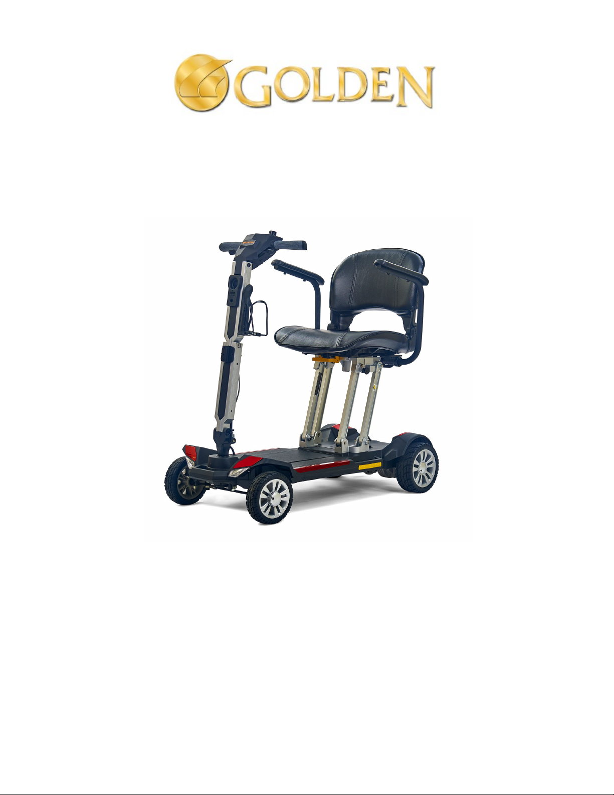
Component: Battery Harness - #2 Figure 2. Lithium Ion Battery Pack
Location: Inside the plastic upper/lower body halves.
Function: Connects the batter y (1) to the contr oller (4), and
the control board inside the scooter deck.
Provides short circuit protection through a 35-amp inline fuse,
located inside the controller cover.
Connections: Connected to the batter y (Bat -) and (Bat +),
controller (Bat -) and (Bat +), control board, and battery fuse.
Refer to the wiring diagram on page 11.
Failure Signs: Open fuse, cor r oded wir es, poor
connections, and poor spring tension can cause the battery
voltage (24-29 volts) not to be supplied to the entire electrical
system.
Make sure the fuse is good, and all connections are good.
Note: Battery pack will not charge if the inline fuse is blown.
Tests: Test the fuse for continuity. Test the har ness for
continuity. See figure 3. Refer to the wiring diagram on
page 11.
Expected Readings: Less than 10 ohms.
Serviceable: Replace the har ness as necessar y.
Replace inline fuse with exact type and rating. Refer to the
wiring diagram on page 11. Figure 3. Battery Harness
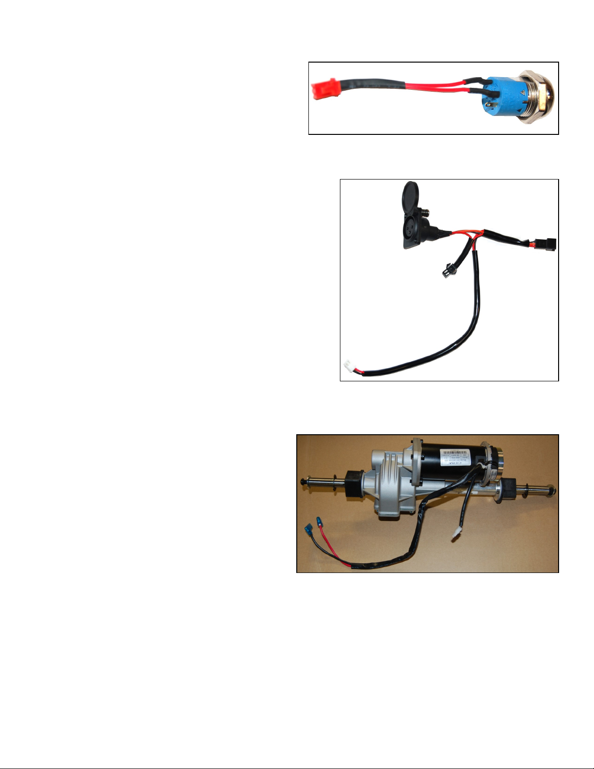
Component: Motor Harness - #3
Location: Rear of the scooter – Inside the plastic
upper/lower body halves. See figure 4. Refer to the
wiring diagram on page 11.
Function: Supplies 24-29 volts from the controller to
the motor.
Connections: Controller (M+) and (M-) and the motor.
See figure 4. Refer to the wir ing diagram on page 11.
Failure Signs: Scooter will not run. The motor is not
receiving the correct 24-29 volt battery voltage from the
controller.
Tests: Test har nesses for continuity. Check connectors.
Make sure the contacts are not corroded and are seated
properly.
Expected Readings: Continuity (less than 10 ohms). Figure 4. Motor Harness (hard wired into motor)
Serviceable: Replace as necessar y.