10 306472
Maintenance
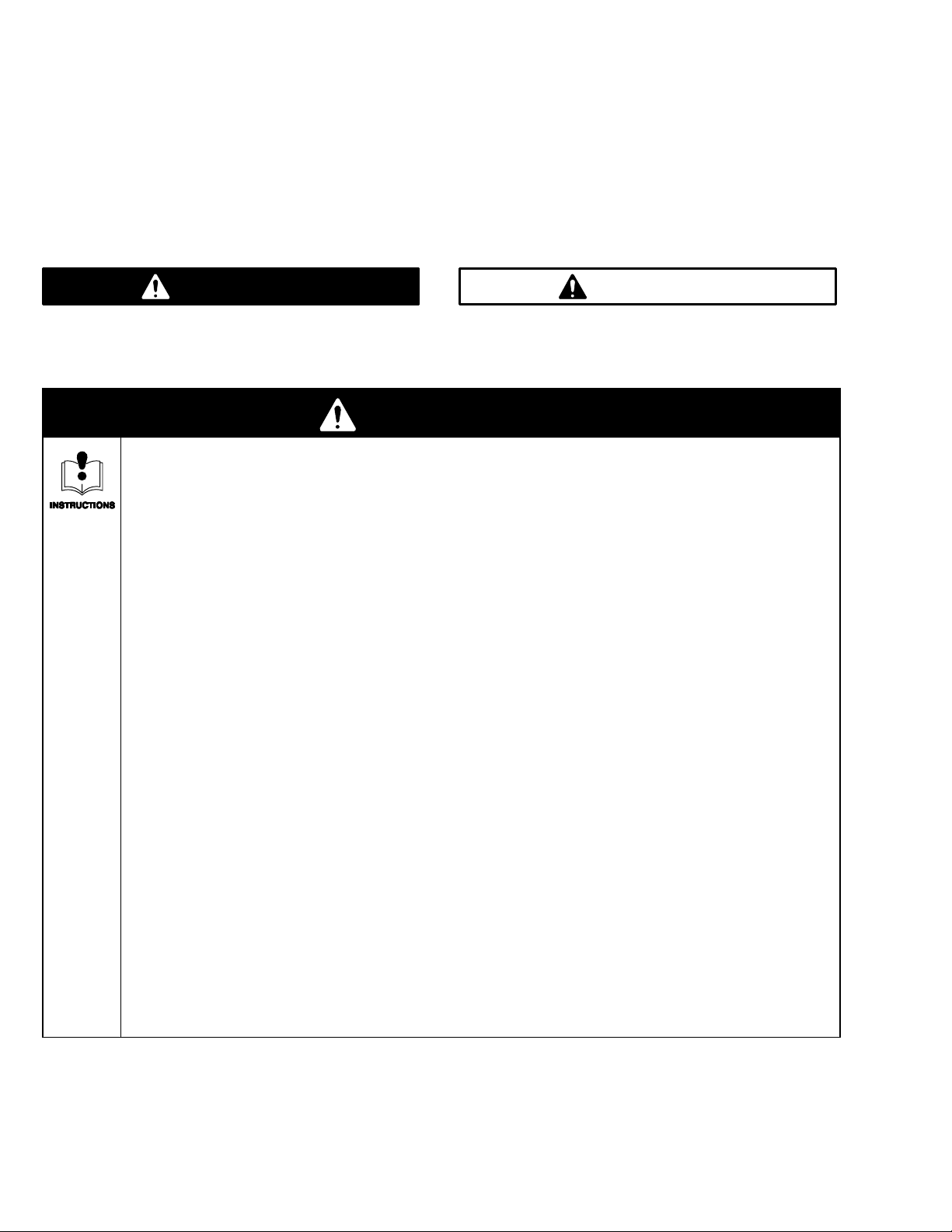
WARNING
To reduce the risk of serious injury whenever you
are instructed to relieve pressure, always follow the
Pressure Relief Procedure on page 8.
1. Remove and clean the strainer in the Evenflo
body, add light oil to the screen cavity and re-
assemble every day.
2. If the pump was not flushed and has not been
operated for more than one day, disconnect the
spray gun fluid hose, turn on the pump, and pump
out a small quantity of fluid. This removes any fluid
that has set-up in the hose.
3. Whenever you are done spraying for the day,
relieve the pressure. Cover the pail to protect it
from contaminants and air, which may cause the
fluid to harden.
NOTE: Be sure you flush the system thoroughly before
any fluid has a chance to set-up or harden.
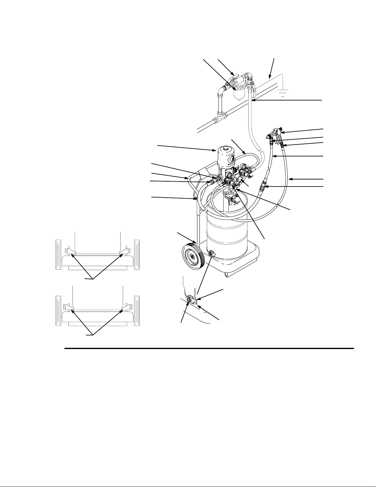
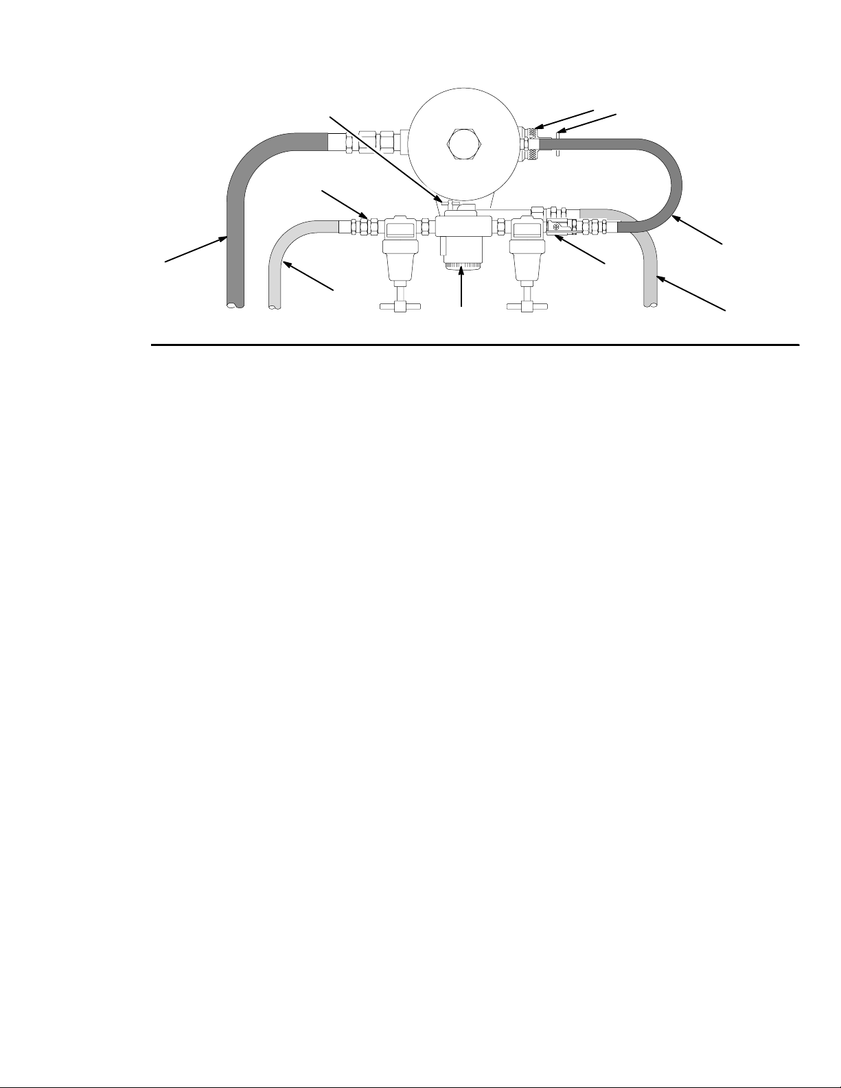
Air Motor Lubrication
If your system does not include an automatic lubrica-
tor, remove the hose (E) to the pump air inlet. Place 15
drops of light machine oil in the inlet. Reattach the
hose and turn on the air to blow the oil into the motor.
Repeat this process every day.
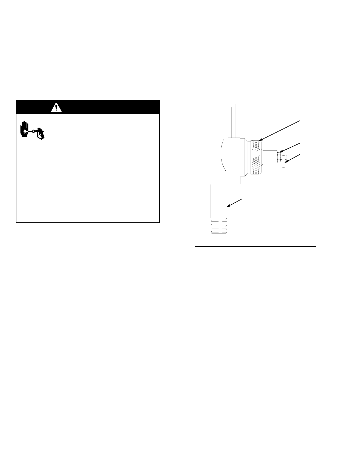
Flushing
WARNING
FIRE AND EXPLOSION HAZARD
Before flushing, read the section FIRE
OR EXPLOSION HAZARD on page 4.
Be sure the entire system and flushing
pails are properly grounded. Refer to
Grounding on page 5.
Flush with a fluid that is compatible with the fluid you
are pumping and with the wetted parts in your system.
Check with your fluid manufacturer or supplier for
recommended flushing fluids and flushing frequency.
Always flush the pump before fluid dries on the dis-
placement rod.
CAUTION
Never leave water or water-base fluid in the pump
overnight. If you are pumping water-base fluid, flush
with water first, then with a rust inhibitor such as
mineral spirits. Relieve the pressure, but leave the
rust inhibitor in the pump to protect the parts from
corrosion.
WARNING
To reduce the risk of serious injury whenever you
are instructed to relieve pressure, always follow the
Pressure Relief Procedure on page 8.
1. Relieve the pressure.
2. Remove the spray gun and clean it according to
the supplied instructions.
3. Raise the pump out of the supply pail and hook the
elevator on the truck handle.
4. Remove the supply pail. Wipe excess fluid off of
the pump. Place the pump in a grounded metal
flushing container, with enough compatible solvent
for flushing the entire system.
5. Open the bleed-type master air valve, the pump
Relax-A-Valve, and start the pump. Circulate the
solvent for at least 15 minutes.
6. Close the Relax-A-Valve. DIrect the fluid hose into
the fluid supply pail. Start the pump. When the
solvent appears at the hose end, quickly transfer
the hose to the flushing pail and allow the pump to
circulate solvent through the pump and hose until
clean.
7. Relieve the pressure.