manuals.online logo
Brands
  1. Home
  2. •
  3. Brands
  4. •
  5. Graco
  6. •
  7. Tools
  8. •
  9. Graco 350 Series Operation manual

Graco 350 Series Operation manual

Important Safety Instructions.
Read all warnings and instructions in this manual.
Save these instructions.
See page 2 for List of Models and Table of
Contents.
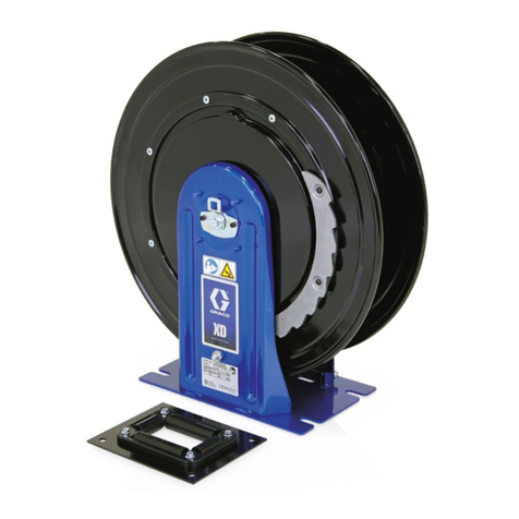
Series 350 Hose Reels
Used to dispense lubrication products, air, water, transmission fluid and antifreeze.
NOTE: These hose reels are for stationary mountings only and cannot be used with enclosures.
WARNING
These hose reels are designed to dispense lube
products, air, water, transmission fluid, or anti-
freeze only. Any other use of these hose reels can
cause unsafe operating conditions and result in
component rupture, fire, or explosion, which could
cause serious bodily injury, including fluid injection.
03711C
308400ZAA
ENG
Instructions–Parts List
2 308400
List of Models
Low-Pressure, Standard Mount
Models Hose Length Maximum Working
Pressure
238213 60 ft (18.3 m) 180 psi
(1.25 MPa, 12.5 bar)
256983 60 ft (18.3 m) 180 psi
(1.25 MPa, 12.5 bar)
243983 50 ft (15.2 m) 180 psi
(1.25 MPa, 12.5 bar)
Medium-Pressure, Standard Mount
Models Hose Length Maximum Working
Pressure
237020 None 1800 psi
(12.4 MPa, 124 bar)
237022 50 ft (15.2 m) 1800 psi
(12.4 MPa, 124 bar)
256984 50 ft (15.2 m) 1800 psi
(12.4 MPa, 124 bar)
High-Pressure, Standard Mount
Models Hose Length Maximum Working
Pressure
237030 none 8000 psi
(55.2 MPa, 552 bar)
237032 50 ft (15.2 m) 5000 psi
(34.5 MPa, 345 bar)
256997 50 ft (15.2 m) 5000 psi
(34.5 MPa, 345 bar)
237034 50 ft (15.2 m) 4000 psi
(27.6 MPa, 276 bar)
Table of Contents
Installation
Typical 5. . . . . . . . . . . . . . . . . . . . . . . . . . . . . . . . . . . . . .
Mounting Options 7. . . . . . . . . . . . . . . . . . . . . . . . . . . . .
Installing a Hose 10. . . . . . . . . . . . . . . . . . . . . . . . . . . . .
Increasing Spring Tension 11. . . . . . . . . . . . . . . . . . . . .
Maintenance 12. . . . . . . . . . . . . . . . . . . . . . . . . . . . . . . . . .
Service 14. . . . . . . . . . . . . . . . . . . . . . . . . . . . . . . . . . . . . .
Parts
Low/Medium Pressure 16. . . . . . . . . . . . . . . . . . . . . . . .
High Pressure 18. . . . . . . . . . . . . . . . . . . . . . . . . . . . . . .
Accessories 20. . . . . . . . . . . . . . . . . . . . . . . . . . . . . . . . . .
Technical Data 23. . . . . . . . . . . . . . . . . . . . . . . . . . . . . . . .
Manual Change Summary 23. . . . . . . . . . . . . . . . . . . . . .
Dimensions 23. . . . . . . . . . . . . . . . . . . . . . . . . . . . . . . . . . .
Graco Standard Warranty 24. . . . . . . . . . . . . . . . . . . . . .
Graco Information 24. . . . . . . . . . . . . . . . . . . . . . . . . . . . .
3308400
Symbols
Warning Symbol
WARNING
This symbol alerts you to the possibility of serious
injury or death if you do not follow the instructions.
Caution Symbol
CAUTION
This symbol alerts you to the possibility of damage to
or destruction of equipment if you do not follow the
instructions.
SKIN INJECTION HAZARD
Fluid from the dispensing valve, leaks, or ruptured components can inject fluid into your body and
cause extremely serious injury, including the need for amputation. Fluid splashed in the eyes or on
the skin can also cause serious injury.
DFluid injected into the skin might look like a minor cut, but it is a serious injury. Seek immediate
surgical treatment.
DDo not point the dispensing valve at anyone or at any part of the body.
DDo not put your hand or fingers over the dispensing valve nozzle.
DDo not stop or deflect leaks with your hand, body, glove, or rag.
DFollow the Pressure Relief Procedure on page 12 if the dispensing valve clogs and before
cleaning, checking, or servicing the equipment.
DTighten all fluid connections before operating the equipment.
DCheck the hoses, tubes, and couplings daily. Replace worn or damaged parts immediately. Do
not repair medium- or high-pressure couplings; you must replace the entire hose.
DDo not attempt to force lubricant into a fitting. If the lubricant is not flowing, stop dispensing
immediately; the fitting may be clogged.
FIRE AND EXPLOSION HAZARD
Improper grounding, poor ventilation, open flames, or sparks can cause a hazardous condition and
result in a fire or explosion and serious injury.
DBe sure the entire fluid system is properly grounded. The hoses supplied with these hose reels
are electrically conductive. The hose reel is grounded by connecting electrically conductive
supply hoses to a properly grounded system. Refer to your pump instruction manual for com-
plete details.
DIf there is any static sparking or you feel an electric shock while using this equipment, stop
dispensing immediately. Do not use the equipment until you identify and correct the problem.
DProvide fresh air ventilation to avoid the buildup of flammable fumes from solvents or the fluid
being dispensed.
DKeep the dispensing area free of debris, including solvent, rags, and spilled gasoline.
DDo not smoke while dispensing flammable fluids.
WARNING
4 308400
EQUIPMENT MISUSE HAZARD
Equipment misuse can cause the equipment to rupture or malfunction and result in serious injury.
DThis equipment is for professional use only.
DRead all instruction manuals, tags, and labels before operating the equipment.
DUse the equipment only for its intended purpose. If you are not sure, call your Graco distributor.
DDo not alter or modify this equipment. Use only genuine Graco parts and accessories. Use only
extensions that are designed for use with your dispensing valve. Modifying parts can cause a
malfunction and result in serious bodily injury.
DCheck equipment daily. Repair or replace worn or damaged parts immediately.
DDo not exceed the maximum working pressure of the lowest rated system component. The
maximum working pressure of your hose reel assembly is indicated on the hose reel identification
plate on the reel pedestal. See also the Technical Data section on page 23.
DUse fluids and solvents that are compatible with the equipment wetted parts. Refer to the Tech-
nical Data section of all equipment manuals. Read the fluid and solvent manufacturer’s warn-
ings.
DDo not use hoses to pull equipment.
DRoute hoses away from traffic areas, sharp edges, moving parts, and hot surfaces. Do not
expose hoses to temperatures above 82_C (180_F) or below –40_C (–40_F).
DDo not lift pressurized equipment.
DComply with all applicable local, state, and national fire, electrical, and safety regulations.
DIf you are adding a service hose and dispensing valve to a bare hose reel, be sure you know the
maximum working pressure of all the components.
DNever use a low-pressure flexible extension designed for low-pressure dispensing valves or
hand-powered lubricating equipment on a medium- or high-pressure dispensing valve.
INSTRUCTIONS
WARNING
HOSE REEL SPRING HAZARD
The spring, which is located behind the flange, is always under great tension and could be propelled
from the lower flange with enough force to cause serious injury.
To reduce the risk of serious injury:
DDo not attempt to remove spring from flange.
DDo not attempt to replace or service the hose reel spring.
TOXIC FLUID HAZARD
Hazardous fluid or toxic fumes can cause serious injury or death if inhaled, swallowed, splashed in
the eyes, or splashed on the skin.
DKnow the specific hazards of the fluid you are using.
DStore hazardous fluid in an approved container. Dispose of hazardous fluid according to all
local, state, and national guidelines.
DAlways wear protective eyewear, gloves, clothing, and a respirator as recommended by the fluid
and solvent manufacturer.
5308400
Installation – Typical Installation
H
KEY
A Main air supply line
B Pump air supply line
C Air filter
D Air regulator
E Bleed-type master air valve (required)
F Pump
G Pump grounding wire (required)
J
L
M
N
Fig. 1
Overhead-Mounted Hose Reel
P
NOTE: Parts are not
proportional.
B
A
C
DE
F
G
J
K
H Fluid drain valve (required)
J Fluid shutoff valve
K Fluid line
L Hose reel fluid inlet kit
M Hose reel
N Dispensing valve
P Mounting channel/base
03791
6 308400
Installation – Typical Installation
The typical installations shown in Fig. 1 is only a guide
for selecting and installing a hose reel system. The
components and accessories shown are the minimum
requirements for all systems. However, it is not an
actual system design. Contact your Graco distributor
for assistance in designing a system to suit your
particular needs.
NOTE: The air and fluid accessories required for your
pump must be properly sized to that pump. Refer to
your specific pump manual for selecting pump
accessories.
Three accessories are required in your system: a
ground wire (G), a bleed-type master air valve (E)
and a fluid drain valve (H). These accessories help
reduce the risk of serious injury, including electric
shock and splashing in the eyes or on the skin.
The ground wire must be connected to the pump
grounding lug and to a true earth ground according
to your local code.
The bleed-type master air valve relieves air trapped
between this valve and the pump after the air is
shut off. Trapped air can cause the pump to cycle
unexpectedly. Locate the valve close to the pump.
The fluid drain valve assists in relieving fluid pres-
sure in the displacement pump, hose, and gun.
Triggering the gun to relieve pressure may not be
sufficient.
WARNING
Air Line Accessories
Install the following accessories in the order shown in
Fig. 1, using adapters as necessary:
DBleed-type Master Air Valve (E): locate down-
stream from the air regulator and for easy access
from the pump.
DAir Regulator (D): controls pump speed and outlet
pressure by adjusting the air pressure to the pump.
Locate the regulator close to the pump but up-
stream from the bleed-type master air valve.
DAir Line Filter (C): removes harmful dirt and
moisture from the compressed air supply.
Fluid Line Accessories
Install the following accessories in the order shown in
Fig. 1, using adapters as necessary:
DFluid Drain Valve (H): install the drain valve point-
ing down but so the handle points up when the
valve is opened.
DFluid Shutoff Valve (J): shuts off fluid to the hose
reel.
DDispensing Valve (N): dispenses the fluid or air.
Required Hose Reel
Installation Accessories
Be sure you have these accessories before starting
the installation. All of these accessories are shown on
pages 20 and 21.
DHose inlet kits (L)
DReel mounting bases, mounting brackets, and
mounting channels (P)
DDispense valves (N)
Mounting Restrictions
DFor stationary mounting only; do not use in any
mobile installation.
DYou can replace the roller support arm on Series
350 hose reels with an accessory-base-mounted
support.
DHose reel enclosures do not fit on these reels.
WARNING
To reduce the risk of injury when mounting a hose
reel overhead, always use a lift truck.
7308400
Installation – Mounting Options
All Mountings
NOTE: Always use large flat washers with the bolts
you use to mount the hose reel pedestal to any
surface.
CAUTION
Be sure the mounting surface is strong enough to
support the reels, the weight of the lubricants, and
the stress caused by hard pulls on the service
hoses. See page 23 for the dry weights of the
hose reel assemblies.
NOTE: All accessories mentioned here are shown on
pages 20 and 21.
1. Select the reel bank mounting location.
a. For high ceilings, suspend a suitable support
structure for the reels, so the hoses will be
long enough to reach your service area.
b. A reel bank mounted in a one-lift service bay
should be at least 6 ft (1.9 m) from the center
line of the lift See Fig. 2.
c. In a two-lift bay, mount the bank equal dis-
tance between the lifts. A bank of all motor oil
reels should be mounted about 5 ft (1.5 m)
from the center of the lift, toward the front of
the lift rails. See Fig. 2.
2. If you are installing permanent supply lines, drill
1.5-in. (38 mm) diameter holes through the ceiling
on the inlet side of the reels.
WARNING
To reduce the risk of injury, when you are mounting
a hose reel overhead, always use a lift truck.
Position the hose reel so the pedestal is facing up.
Using the lift truck, raise the reel as close to the
mounting location as possible. Bolt the hose reel to
its mounting, and be sure it is secure before lower-
ing the lift truck.
Fig. 2
5’ (1.5 m)
for motor oil
1639
1
3
2
1
2
6’ (1.9 m) minimum
for 1 lift
Center between
two lifts
3
8 308400
Installation – Mounting Options
Ceiling Mounting Without an I-Beam
1. Install the mounting frame (303) and base plate
(304) as shown in Fig. 3.
03718B
Fig. 3
303
305
301
304
301
302
2. Determine the desired position of the roller support
arm (37)
DThe hose reel is factory-assembled and shipped
with the roller support arm (37) in position AA. If
position AA, BB, CC, or DD is desired, continue
with step 3. See Fig. 4.
DIf the desired roller support arm (37) position is EE
or FF, rotate the ratchet (31) clockwise one screw
hole (60_). This will assure retraction when the
hose is at maximum extension. See Fig. 5.
3. Slide the hose reel onto the base plate (304) and
install the hold-down plate (302) and capscrew
(301). Tighten the screw firmly. See Fig. 3.
4. Connect the supply line to the inlet hose of the
reel. Purchase the hose inlet kit separately. See
Accessories on page 20.
5. Adjust the spring tension of the reel. Hose reels
shipped with hoses come from the factory with the
tension preset for a typical installation. To adjust
for more or less tension, see Increasing Spring
Tension on page 11. If you have purchased a
bare hose reel, see Installing a Hose on a Bare
Reel on page 10.
TI1710A
BB
CC
AA
(As Shipped)
DD
31
Fig. 4
TI1710A
FF
EE
31
Fig. 5
37
18
1Torque to 25–35 ft. lbs.
1
9308400
Installation – Mounting Options
Ceiling Mounting Directly to an I-Beam
NOTE: The reel base is slotted (A) to allow two screws
to be started before mounting the reel to the support.
See Fig. 3.
1. Using the template (B) provided, drill holes in the
I-Beam (C). See Fig. 6.
2. Continue with Step 2 of Ceiling Mounting With-
out an I-Beam on page 7.
Ceiling Mounting to an I-Beam Without
Drilling Holes
NOTE: All accessories mentioned are shown on pages
20 and 21.
1. Secure two accessory mounting brackets (D) as
shown in Fig. 7. Use two mounting brackets for
each 1 to 3 capacity mounting channels (F).
2. Position the adjustable clamps (E) of the mounting
brackets over the I-Beam (C), and tighten them
securely. See Fig. 7.
3. Continue with Step 2 of Ceiling Mounting With-
out an I-Beam on page 7.
Wall Mounting
NOTE: All accessories mentioned are shown on pages
20 and 21.
1. Select the reel bank mounting location. Mount the
reel to a wall, using the provided template (B) for
laying out the holes you drill.
You can mount an accessory base plate (304) to
the wall for easier removal of the hose reel for
servicing. See Fig. 8.
2. Continue with Step 2 of Ceiling Mounting With-
out an I-Beam on page 7.
Fig. 6
A
B
C
03719C
1655
Fig. 7
EC
D
F
Fig. 8
304
B
03720C
10 308400
Installation – Installing a Hose
Installing a Hose on a Bare Reel
1. Locate the length and size of your hose in the
chart below. Note how many times you must turn
the reel to properly adjust the spring tension.
Hose Length No. of Reel Turns
50 ft (15.2 m) 13
60 ft (18.3 m) 15
2. Place a piece of tape on the side of the reel flange
to use as a visual reference to help you count the
number of reel turns.
WARNING
Always wear heavy gloves when you adjust the
spring tension to protect your hands from being cut
on the hose reel.
3. Wearing heavy gloves, firmly grab the outside
edge of the reel flange with both hands. See
Fig. 10. Wind the reel the proper number of turns,
rotating it in the direction shown in Fig. 10, and
stop only at latching locations. Stop the reel where
there is access to the hose swivel (34) (see Fig. 9)
and where the reel is securely latched.
4. Before you install the hose, attach a C-clamp (G)
to the reel flange to help prevent the reel from
unintentionally becoming unlatched and spinning
freely. See Fig. 10.
WARNING
Never allow the reel to spin freely. Doing so causes
the hose to spin out of control, which could cause
serious injury if you are hit by the hose.
5. Uncoil and extend the hose. Assemble the hose
stop (47) to the outlet end of the hose (48) and
tighten. See Fig. 11 on page 11.
6. Attach the hose (48) to the hose reel swivel (34),
and carefully remove the C-clamp. See Fig. 9.
7. Pull the hose hard enough to release the latch,
and slowly allow the hose to retract.
8. Position the hose stop (47) so the hose extends
far enough for all operators to reach the dispens-
ing valve. See Fig. 11 on page 11.
NOTE: The reel base (303) has two holes (H). Run the
inlet hose through either hole, depending on the
orientation of the hose reel. See Fig. 11 on page 11.
Fig. 9
34
48
03722
Fig. 10
26
48
22
G
03723D
11308400
Installation – Increasing Spring Tension
Increasing Spring Tension
1. Pull the hose out fully, and engage the latch.
2. Pull the hose (48) back through the hose rollers
(22). See Fig. 11.
3. Wrap a loop of hose onto the reel flange (26).
4. Check the spring tension; the hose must pull out
fully and retract fully. Wrap more loops, one at a
time, around the reel flange until the spring has the
desired tension.
NOTE: Do not put so many loops onto the reel that the
spring winds up tightly before the hose is fully
extended. Remove loops to decrease tension.
CAUTION
A spring that is wound too tightly prevents the hose
from getting pulled out all the way, which puts
excessive strain on the hose and reel spring and
could damage the reel.
Fig. 11
DETAIL A – Hose Inlet Kits
J
K
L
304
45
34
302
301
H
1641
403
402
48
49
22
26
1
2
To supply line
Position hose stop (47)
for operator’s reach
1
2
303
1642C
12 308400
Maintenance
Pressure Relief Procedure
SKIN INJECTION HAZARD
To reduce the risk of serious injury,
including fluid injection, splashing in the
eyes or on the skin, or injury from mov-
ing parts, always follow this procedure whenever
you shut off the pump, and before inspecting,
removing, cleaning or repairing any part of the
pump or system.
WARNING
1. Close the supply pump’s bleed-type master air
valve (required in pneumatic systems).
2. Open the dispensing valve until pressure is fully
relieved.
3. Open the fluid drain valve at the pump fluid outlet.
Leave the drain valve open until you are ready to
use the system again.
If you suspect that the dispensing valve, extension, or
grease fitting coupler is clogged, or that pressure has
not been fully relieved after you have followed the
steps above, very slowly loosen the coupler or hose
end coupling to relieve the pressure gradually, then
loosen it completely. Then clear the clog.
Replacing the Service Hose
1. Relieve the pressure.
SKIN INJECTION HAZARD
To reduce the risk of serious injury
whenever you are instructed to relieve
pressure, always follow the Pressure
Relief Procedure above.
WARNING
2. Fully extend the hose and latch it.
3. Attach a C-clamp (G) to the reel flange to help
prevent the reel from unintentionally becoming
unlatched and spinning freely. See Fig. 12.
Never allow the reel to spin freely. Doing so causes
the hose to spin out of control, which could cause
serious injury if you are hit by the hose.
WARNING
4. Disconnect and remove the service hose.
5. Attach the hose (48) to the hose reel swivel (34),
and carefully remove the C-clamp. See Fig. 13.
6. Pull the hose hard enough to release the latch,
and slowly allow the hose to retract.
7. Position the hose stop so the hose extends far
enough for all operators to reach the dispensing
valve.
Fig. 12
36
37
G
03724C
Fig. 13
34
48
0372
2
13308400
Maintenance
Lubrication
Every six months, apply one or two drops of light
motor oil to lubricate the hose reel at point A. See
Fig. 14.
Fig. 14 A03722
26
14 308400
Service
Swivel
1. Relieve the pressure.
SKIN INJECTION HAZARD
To reduce the risk of serious injury
whenever you are instructed to relieve
pressure, always follow the Pressure
Relief Procedure on page 12.
WARNING
2. Disassemble the parts as shown in Fig. 15 and 16
(depending on your hose reel model). Clean the
parts, and inspect them for wear or damage.
3. Grease the new parts, and lubricate the cavity of
the swivel assembly (34) with high-quality grease.
Install the parts as shown in Fig. 15 or 16, depend-
ing on your hose reel model.
Fig. 15 Medium-Pressure Hose Reel
39
34
15
20
15
11
12
15
20
15
1
3
48
03726
21
PACKING DETAIL
Fig. 16 High-Pressure Hose Reel
1645
34 39
46 12 20
15
11
15
12 20
PACKING DETAIL
O-ring MUST be cradle
d
in backup o-ring
Lubricate cavity
with grease
1
3
2
1
Lips of v-packings
MUST face reel flange
2
48
21
Latch
If the reel latch malfunctions or becomes sluggish,
disassemble the latching mechanism. See Fig. 17.
Clean and lubricate or replace the broken or worn
components as necessary.
LATCH ASSEMBLY
Fig. 17
36
30
5
17
7
19
4
30
29
38
03739A
1Torque to 25–35 ft. lbs.
1
15308400
Notes
16 308400
Parts List – Low/Medium Pressure
Medium Pressure Hose Reels
Model 237020, Series D
Bare Hose Reel, 1800 psi (124 MPa, 124 bar)
Includes items 1 to 41
Model 237022, Series D
Hose reel with 50 ft (15.2 m), 1800 psi (12.4 MPa,
124 bar) hose
Includes items 1 to 45 and 49
Model 256984, Series D
Hose reel with 50 ft (15.2 m), 1800 psi (12.4 MPa,
124 bar) hose
Includes items 1 to 45 and 49
Low Pressure Hose Reels
Model 238213, Series E
Hose reel with 60 ft (18.3 m),180 psi (1.25 MPa,
12.5 bar) hose
Includes items 1 to 45 and 52
Model 256983, Series E
Hose reel with 60 ft (18.3 m),180 psi (1.25 MPa,
12.5 bar) hose
Includes items 1 to 45 and 52
Model 243983, Series E
Hose reel with 50 ft (15.2 m),180 psi (1.25 MPa,
12.5 bar) hose
Includes items 1 to 45 and 53
Ref
No. Part No. Description Qty
1 218591 HOSE ROLLER KIT;
Includes items 1a to 1e
1a 178675 SBRACKET, roller 1
1b 107439 SSCREW, machine; #10 x 3/4” 4
1c 178670 SROLLER, hose 4
1d 178705 SPIN, dowel 4
1e 102920 SNUT, lock; #10 4
4 101044 WASHER 1
5 101079 RING, retaining 1
7 102039 PIN, straight 1
9 105332 NUT, lock, hex; M5 x 0.08” 6
10 113267 KEY, square, parallel; 3/16” x 1” 1
11 106082 RING, retaining, external 2
12 106083 RING, retaining external 1
13 106084 SCREW, machine; M5 x 10 6
15* 108235 WASHER, backup 2
17 110974 BEARING 1
18 111800 SCREW, cap, flange head;
5/16–18 x 5/8” 9
19 112731 NUT, flanged, 1/2–13 UNC–2B 1
20* 166702 O-RING 2
21 177679 WASHER, retaining 8
24 178681 HUB, reel 1
26 FLANGE SET, reel (may not be
purchased separately) 1
28 111220 RING, retaining 1
29 186583 SPRING, torsion 1
30 276382 DOG, ratchet 1
31 276386 RATCHET 1
33Y187034 LABEL, warning 1
34 187559 SWIVEL, ASSEMBLY 1
35 189056 TAG, Caution (not shown) 1
36 198285 REEL PEDESTAL 1
37 15F311 ROLLER SUPPORT
(includes item 33) 1
38 189984 STUD 1
Ref
No. Part No. Description Qty
39 217430 UNION, swivel;
3/8 npt(m) x 1/2 npsm(f); for
Models 237022, 256984, and
243983 1
155494 UNION, swivel;
3/8 npt(m) x 3/8 npsm(f); for
Model 238213 1
41 194030 REEL SHAFT; for Models 237020
237022, and 256984 1
194036 REEL SHAFT; for Models 238213
and 243983 1
42Y306297 TAG, information (not shown) 1
45 218340 HOSE STOP KIT; for Model
238213 1
218341 HOSE STOP KIT; for Models
237022, 256984, and 243983 1
49 221093 HOSE, 1/2” ID, cpld 1/2 npt (mbe)
50 ft (15.25 m), 1800 psi (12.4 MPa,
124 bar) Maximum Working
Pressure 1
52 249182 HOSE, 3/8” ID, cpld 3/8 npt (mbe)
60 ft (18.3 m), 180 psi (1.25 MPa,
12.5 bar) Maximum Working
Pressure 1
53 248313 HOSE, 1/2” ID, cpld 1/2 npt (mbe)
50 ft (15.2 m), 180 psi (1.251 MPa,
12.5 bar) Maximum Working
Pressure 1
54 110996 NUT, hex, flanged; 5/16–18 3
55 186580 NUT, hex; 1/2 npsm 1
* These parts are also included in Repair Kit
224450, which may be purchased separately.
Keep a repair kit on hand to reduce down time.
YReplacement Warning labels, tags, and cards are
available at no cost.
17308400
Parts Drawing – Low/Medium Pressure
05390E
Detail for Placement of Washers (21)
37
18
4
19
45
10
41
38 7
29 17
5
31
11 21d
26
13
21c
24
39
Ref 49, 52, or 53
21a
11
34
15
15
26
21b
30
9
36
20
12
03715
49, 52, or 53
21c
21d
21b
21a
1
2
Use at least one washer
(21) here
Use four washers here
2
1
3.030 maximum clearance
3
2
1
28
1b
1a
1c
1d
1e
55
54
18
33
4Torque to 25–35 ft. lbs.
5Torque to 85–105 ft. lbs.
4
4
4
5
18 308400
Parts List – High Pressure
Model 237030, Series D
Bare hose reel
Includes 4 to 46
Model 237032, Series D
Hose reel with 50 ft (15.2 m), 5000 psi (34.5 MPa,
345 bar) hose Includes items 1 to 47, 49
Model 256997, Series D
Hose reel with 50 ft (15.2 m), 5000 psi (34.5 MPa,
345 bar) hose Includes items 1 to 47, 49
Model 237034, Series D
Hose reel with 50 ft (15.2 m), 4000 psi (27.6 MPa,
276 bar) hose Includes items 1 to 46, 51, 52
Ref
No. Part No. Description Qty
1 218591 HOSE ROLLER KIT;
Includes items 1a to 1e
1a 178675 SBRACKET, roller 1
1b 107439 SSCREW, machine; #10 x 3/4” 4
1c 178670 SROLLER, hose 4
1d 178705 SPIN, dowel 4
1e 102920 SNUT, lock; #10 4
4 101044 WASHER 1
5 101079 RING, retaining 1
7 102039 PIN, straight 1
9 105332 NUT, lock, hex; M5 x 0.08” 6
10 113267 KEY, square, parallel; 3/16” x 1” 1
11 106082 RING, retaining, external 2
12* 150419 GLAND, male 1
13 106084 SCREW, machine; M5 x 10 6
15* 155938 GLAND, female 1
17 110974 BEARING 1
18 111800 SCREW, cap, flange head;
5/16–18 x 5/8” 9
19 112731 NUT, flanged, 1/2–13 UNC–2B 1
20* 150418 V-PACKING, leather 4
21 177679 WASHER, retaining 8
24 178681 HUB, reel 1
26 FLANGE SET, reel (may not be
purchased separately) 1
28 111220 RING, retaining 1
29 186583 SPRING, torsion 1
30 276382 DOG, ratchet 1
31 276386 RATCHET 1
33Y187034 LABEL, warning 1
34 201882 SWIVEL ASSEMBLY 1
35Y189056 TAG, Warning (not shown) 1
36 198285 REEL PEDESTAL 1
37 15F311 ROLLER SUPPORT
(includes item 33) 1
Ref
No. Part No. Description Qty
38 189984 STUD 1
39 15Y397 UNION, swivel; 3/8 npt 1
41 194035 REEL SHAFT 1
42Y306297 TAG, information (not shown) 1
46* 167528 SPRING 1
47 222225 HOSE STOP KIT 1
49 109158 HOSE, 1/4” ID, cpld 1/4 x 3/8 npt
(mbe), 50 ft (15.25 m), 5000 psi
(34.5 MPa, 345 bar) Maximum
Working Pressure 1
51 218340 HOSE STOP KIT 1
52 109170 HOSE, 3/8” ID, cpld 1/4 x 3/8 npt
(mbe), 50 ft (15.25 m), 4000 psi
(27.6 MPa, 276 bar) Maximum
Working Pressure 1
54 110996 NUT, hex, flanged; 5/16–18 3
55 186579 NUT, hex; 3/8 npsm 1
*These parts are also included in Repair Kit
237094, which may be purchased separately.
Keep a repair kit on hand to reduce down time.
YReplacement Warning labels, tags and cards are
available at no cost.
19308400
Parts Drawing – High Pressure
05392F
5
30
37
18
4
19
1b
1a
1c
1d
1e
10
41
38 7
29 17
31
11
26
13
24
39
Ref 49 or 52
11 46
34
15
12
20
26
9
36
47 or 51 49 or 52
03713
33
21a
1
2
Use at least one washer (21) here
Use four washers here
1
3.030 maximum clearance
3
Detail for placement of washers (21)
21d 2
21a
21b
21c
21b 21c
21d 2
28
55 54
18
Torque to 25–35 ft. lbs.
5Torque to 85–105 ft. lbs.
4
4
4
4
5
20 308400
Accessories – Mounting
Must be purchased separately. Use only genuine Graco parts and accessories.
Order mounting hardware as needed per items 1 and 2 below.
1: Mounting Bracket 204741
Secures mounting channel to I-beam without holes
drilled in I-beam. Bracket fits all standard I-beams with
flanges up to 7 in. (178 mm). Mount the bracket to the
mounting channel before securing it to the I-beam.
This mounting bracket will work on 1- to 6-reel mount-
ing channels. Screws, lockwashers, and nuts are
included.
NOTE:
For one to three reels, two of 204741 are required.
For four to six reels, three of 204741 are required.
1655
adjustable clamps I-beam
mounting
bracket
mounting channel
2: Mounting Channels
For mounting open hose reels to ceiling. Includes
mounting channel, base plate, hold down plate, cap
screws (3/8–16 UNC –2a X 0.625 in), lockwashers,
and weldnuts on channel.
241791 for 1 reel
241792 for 2 reels
241793 for 3 reels
241794 for 4 reels
241795 for 5 reels
241796 for 6 reels

Other manuals for 350 Series

1

This manual suits for next models

10

Other Graco Tools manuals

Graco Ultra-lite A Series Operation manual

Graco

Graco Ultra-lite A Series Operation manual

Graco Pro–Shot 242055 B Series Operation manual

Graco

Graco Pro–Shot 242055 B Series Operation manual

Graco 200 Series Operation manual

Graco

Graco 200 Series Operation manual

Graco DutyMax 24M054 Assembly instructions

Graco

Graco DutyMax 24M054 Assembly instructions

Graco 24N719 User manual

Graco

Graco 24N719 User manual

Graco 350 Series Operation manual

Graco

Graco 350 Series Operation manual

Graco 245820 User manual

Graco

Graco 245820 User manual

Graco SD Series User manual

Graco

Graco SD Series User manual

Graco SDX Series User manual

Graco

Graco SDX Series User manual

Graco Twistork 224854 Parts list manual

Graco

Graco Twistork 224854 Parts list manual

Graco SD Composite Series User manual

Graco

Graco SD Composite Series User manual

Graco 223-440 Operation manual

Graco

Graco 223-440 Operation manual

Graco 24M510 Owner's manual

Graco

Graco 24M510 Owner's manual

Graco 17J866 User manual

Graco

Graco 17J866 User manual

Graco 17Y907 Instruction Manual

Graco

Graco 17Y907 Instruction Manual

Graco 309446A Parts list manual

Graco

Graco 309446A Parts list manual

Graco 241105 Operation manual

Graco

Graco 241105 Operation manual

Graco 208-327 Operation manual

Graco

Graco 208-327 Operation manual

Graco GX-16 User manual

Graco

Graco GX-16 User manual

Graco 750 Series User manual

Graco

Graco 750 Series User manual

Graco 257815 User manual

Graco

Graco 257815 User manual

Graco LD Series User manual

Graco

Graco LD Series User manual

Graco PT2000 User manual

Graco

Graco PT2000 User manual

Graco 241623 User manual

Graco

Graco 241623 User manual

Popular Tools manuals by other brands

OYPLA DIY 3386 user manual

OYPLA DIY

OYPLA DIY 3386 user manual

Wetekom 45 75 07 instruction manual

Wetekom

Wetekom 45 75 07 instruction manual

REAL AVID Master Sight Pusher quick start guide

REAL AVID

REAL AVID Master Sight Pusher quick start guide

RED ROOSTER RRI-BA16BOA H19 manual

RED ROOSTER

RED ROOSTER RRI-BA16BOA H19 manual

RED ROOSTER RRI-BIM25T manual

RED ROOSTER

RED ROOSTER RRI-BIM25T manual

HOZAN C-402 instruction manual

HOZAN

HOZAN C-402 instruction manual

Findeva FKL in Series Installation and operating instructions

Findeva

Findeva FKL in Series Installation and operating instructions

Niigata seiki JLVC-30 user manual

Niigata seiki

Niigata seiki JLVC-30 user manual

Beta 1899SI Operation manual and instructions

Beta

Beta 1899SI Operation manual and instructions

Bosch GSR 18 V-EC Original instructions

Bosch

Bosch GSR 18 V-EC Original instructions

Josef Kihlberg JK20-680 operating instructions

Josef Kihlberg

Josef Kihlberg JK20-680 operating instructions

Powerfix Profi 71825 translation of original operation manual

Powerfix Profi

Powerfix Profi 71825 translation of original operation manual

Victaulic VE416FS Operating and maintenance instruction manual

Victaulic

Victaulic VE416FS Operating and maintenance instruction manual

Festool MX 1200 E EF instruction manual

Festool

Festool MX 1200 E EF instruction manual

Esogetics PERLUX P 117 instructions

Esogetics

Esogetics PERLUX P 117 instructions

Sealey WK025.V2 instructions

Sealey

Sealey WK025.V2 instructions

AGI W13 Operator's manual

AGI

AGI W13 Operator's manual

Bosch GSG 300 Professional Original instructions

Bosch

Bosch GSG 300 Professional Original instructions

manuals.online logo
manuals.online logoBrands
  • About & Mission
  • Contact us
  • Privacy Policy
  • Terms and Conditions

Copyright 2025 Manuals.Online. All Rights Reserved.