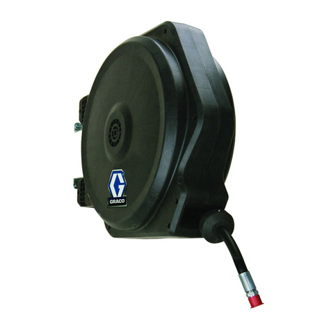
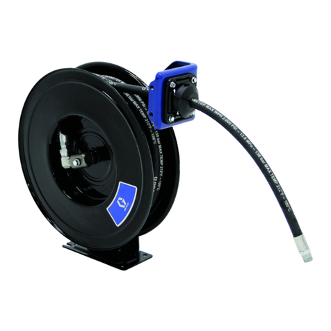
Graco 200 Series Operation manual

307
-
694
This
manual
contains
IMPORTANT
Rev
R
Supersedes
P
WARNINGS
and
INSTRUCTIONS
GRACO
READAND
RETAIN
FOR
REFERENCE
a
SERIES
200
H
E
NOTE:
See
pages4,5,and6for
Hose
Reel
partnumbers,
descriptions, and maximum working pressure
information.
TWO
REEL BANK SHOWN
WITH ACCESSORY ENCLOSURES
GRACO INC.
P.O.
BOX
1441 MINNEAPOLIS, MN 55440
-
1441
@COPYRIGHT
1985.
GRACO
INC.

Page Sectlon Page Section
3
Warnings
14
Installation
Importantinformationonhowloreduce
the
riskof
HOW
to insall hose reels, adjust reel spring ten
-
injurywhen usingthis equipment. sion, and install hosereelenclosures.
4
Hose
Reel
ModelChart
4 Open
Hose
Reel Assemblies
Modelorder numbersfor reel assemblies.
6
Enclosed
Hose
Reel
Assemblies
17
Maintenance
How
to
lubricatethe reel. increasespringtension
andreplace
a
service
be.
How
to
repair
the
swivel, reelspringand latch.
18
Repalr
7
Hose Reel
Assemblies
-
Parts
Lists
20
Bare
Hose
Reel
-
PartsLists
&
Drawlngs
identifies
comwnents received with each hose
Parts
listsand drawingsfor barehosereds. only.
~~ ~~~
..
reel assembly. Use these parts lists to order
replacementcomponents.
20
Bare
Hose
Reel
218-344
22
Bare
Hose
Reel
218-345
--
.
7
Basic Chassis Grease
Reels
7
Basic Oil
&
Light Lubricant
Reels
-
8
Basic
Air
&Water
Reels
8
Open
&
EnclosedChassis Grease
Reels
9 Open
&
EnclosedMotor Oil Reels
9 Open&.EnclosedATF
Reels
10
Open
&
EnclosedGear Lube Reels
11 Open
&
EnclosedMotor Oil Reels
11
Open
&
EnclosedATF Reels
with Electronic FluidMeters
12
Open
&
EnclosedGear
Lube
Reels
with Electronic FluidMeters
13 Open
&
EnclosedAir
Reels
with ElectronicFluidMeters
13 Open
&
EnclosedWater
Reels
24
ReelEnClOSUreS
-
Parts
Llsts
&
Drawings
Partslistsand drawingsforsideenclosure
kit
and
end enclosure
kit.
25
AccesSOrleS
tionaccessories.
Parts
listsanddrawingsfor mountingandinstalla-
26
Dimensions
Overall dimensionsand weights of hose
reels,
26
Technlcal Data
Wened pans and maximum working pressuresof
bare hosereels.
Cover
Back GracoWarranty
Be
sure
you
read and understand
each
of
these terms FLEXIBLE EXTENSlON
A
flexible rubber hose extending
beforereadingthe rest
of
the manual. from the dispensing valve.
to
which a greasefitting coupler
is
WARNING Alerts user to avoid or
correct
conditions that
couldcause bodilyinjury. RIGIDEXTENSlON.
A
rigidtubeextendingfrom the dispens-
CAUTION
Alertsusertoavoidorconectconditionsthatcould
ingvalve, lowhich
a
greasefining coupler isanached.
damage or destroyequipment. GREASEFlTTING
COUPLER
The
deviceat the end of
the
NOTE
Givesfurtherexplanationof aprocedureor helpfulhints. lubricated.
flexible or rigid extension that connects to the parts
to
be
anached.
!
2
307
-
694

Fluidemittedunderhighpressurehomleaksorrupturedcompo
-
nentscanpenetratetheskinandcauseextremelyseriousbodily
injury,inciudingtheneedfor amputation.AIs0,fluidinjectedinto
or splashed intothe eyes cancause seriousdamage.
The
MMMUM
WORKiNG
PRESSURE
Of
your hose reelassem-
System Pressure
biy
isdetermined
by
thelowest
-
ratedcomponentintheassem
-
bly. The HOSE REEL MODEL charts on pages
4
to
6
give the
maximumworkingpressureoftheassemblieslistedthere.
If
you
are addingasewice hoseand dispensingvalve to a bare hose
reel,
be
sure you know the maximum working pressureof all
components1
To reducethe risk of serious bodily injury, includingfluid
Pressure Rellef Procedure
from movingparts.alwaysfollowthisprocedurewhenev-
injection. splashing inthe eyes or
on
the skin, or injury
er you shut
off
the pump,andbeforeinspecting,remov
-
ing,cleaningor repairingany partof the pumporsystem.
2.
Closethe supply pump'sbleed
-
type masterair valve
1.
Closethe supply pump'sair regulator.
3.
Open the dispensing valve until pressure is fully
(requiredinpneumaticsystems).
If
yoususpect the dispensingvalve, extension or grease
relieved.
fitting
coupierisdogged, or that pressurehasnotbeen
fully relievedafter foiiowing all the steps above, VERY
SLOWLY lwsenthe couoier or hose end CouDiina and
allow pressureto be relievedgradually,then
ibs&
the
part completely. Now clear the clog.
Do
not modifyany partof the dispensingvalve. Onlyuseexten-
DispensingValve Safety
siansandgreasefittingcouplerswhicharedesignedforusewith
yourdispensingvalve. Modifyingpartscancauseamalfunction
and result in serious bodilyinjury.
Flexible Extension
Safety
extensionyou are using. Never exceedthat pressure,even
if
Be
sureyouknowthe maximumworking pressureof the flexible
your dispensingvalve and/or pump
is
ratedfor higher working
pressures.
..
Never use a low pressure, flexibleextension,designedfor low
pressuredispensingvalves or hand
-
poweredlubricatingequip
ment,
on
a high
-
pressuredispensingvalve.
Neverattemptto force the lubricantinto
a
fitting1
If
thelubricant
isnotflowing, STOP DISPENSING IMMEDIATELY.
The
fitting
may be clogged. Forcing lubricant may cause excessive back
pressureintheflexibieextension,whichcouidcauseittoNpture
and result in serious bodily injury, including
fluid
injectionand
eye injury.
Grease FittingCoupler Safety
Use
extreme caution when cleaningor changing grease fitting
couplers.
if
the coupler clogs while dispensing, STOP
DIS
-
PENSING IMMEDIATELY.
Follow
the Pressure Relief Proce-
builduparound the coupler until pressure isfully relieved.
dure
,
at left.Thenremovethecouplertocleanit.Neverwipe
off
GeneralSafety
Checkthe operationofallequipmentsafetydevicesbeforeeach
use.
NEVER pointthe dispensingvalve at anyoneor any
parl
of
the
body.
NEVER put your handor fingersover the greasefittingcoupler.
NEVER alter or modifyany part of this dispensing equipment;
doing
so
couldcause
it
to malfunction.
CHECK
all dispensingequipment regularly. Repair or replace
worn or damagedparts immediately.
NEVER
try
to stop or deflect leaks
with
your handor body,
Medical
Treatment
...
-
-.
-
-.
.
.
-
-
..
.
.
-..
.
If
any fluid appears to penetrateyour skin, get EMERGENCY
.
MEDICAL CARE AT ONCE.
DO
NOT TREAT AS A SIMPLE
CUT1
Tell
thedoctor exactly what fluidwas injected.
Note
to
Physician: injectionintothe skin isa traumatic
injuw
It
isimportanttolreat the injurysurgically
as
soon
as
possl-
ble.DonotdeiaytreatmenttoresearchtoxicityToxicityisacon-
cernwithsome exotic coatingsinjecteddirectlyintothe blood
stream. Consultationwith a plastic surgeon or reconstructive
handsurgeonmaybeadvisable.
USE
EXTREME CAUTIONWHEN HANDLINGTHE SPRING!
Thespring, whichislocatedbehindthe flange, isALWAYSunder
greattension andcouldbepropelledfrom the lowerflange
with
TO reduce the risk of serious bodily injury when replacingthe
enoughforcetocauseserious bodily injury.
spring, useextremecautionwhen removingthetop reelflange.
flangeto exposethe spring.
Be sure the reel
is
laying flat, and then carefully lift
up
on
the
ALWAYS use lockingpliersto compress and holdseveral row
of the spring together when removing and when installing a
spring. See Fig
1.
Beforedisposingofthespring,carefullyanachaminimumoftwo
hoseclamps aroundthe keeper andspring bandsas shownin
Fig
2.
HOSE
Fig
2
CLAMP
307
-
694
3
Order
No.
consists
of
Bare Hose Reel
218-344,
plus:
Maximum
Dispensing Parts
ORDER
NO.
Hose
Valve Pressure
Working Breakdown
on Page:.
CHASSIS
GREASE
7
5000
psi
(350
bar)
None
114
"
ID
x
20'
218-440
218-441
7
5000
psi
(350
bar)
None
114
"
ID
x
35'
218-442
8
5000
psi
(350
bar)
223-903
114"
ID
x
35'
218-443
0
5000
psi
(350
bar)
223-903
114"
ID
x
20'
me
of
Service
OIL
&
L
I
G
HT
LUBRICANTS
MOTOR
OIL
ATF
GEAR
LUBE
I
i
I
!
i
:
1
i
4
307
-
694

Order
No.
consists
of
Bare
Hose
Reel
218
-
345,
plus:
Maximum
Dispensing
~,
Parts
Working Breakdown
Type
of
Service
ORDER
NO.
on
Page:Pressure
Valve
Hose
AIR
or
WATER
180
psi (12bar)
180-885
318"
ID
X
40'
21
8-459
180
psi (12bar)
180-685
114
"
ID
X
40'
21
8-458
WATER
180
psi
(12
bar)
218
-
545
318"
ID
x
40'
21
8
-
457
180
psi
(12
bar)
218-544
114
"
ID
x
40'
21
8-456
AIR
180
psi
(12
bar)
None
318
"
ID
X
40'
21
8-455
180
psi (12bar)
None
114"
ID
X
40'
21
8-454
8
8
13
13
13
13
Hose reels are available
in
the
following
four
levels:
One of these reels is used in all other reek inthis manual. Bare reelsdo not include
Bare Hose Reels are available ina highpressure
model
and a
low
pressuremodel.
hoses, valves or enclosures.
kit (except Model
218-543),
and a
hose
stop kit. There are three types
of
basic hose
Basic
Hose
ReelAssemblies includea bare hose reel, asewice hose, a hose inlet
reels: HighPressure GreaseReel, Low PressureOil
&
Light Lubricants
Reel,
andLow
Pressure
Air
&
Water
Reel.
OpenHoseReelAssemblies includeabasichosereelandadispensingvalve.Some
models includean electronicallymetereddispensingvalve.
adispensingvalve.
Some
modelsincludeanelectronicallymetereddispensingvalve.
Enclosed ReelAssemblies includean openhose reel and a side enclosure kit, and
Endenclosure kits must be purchased separately
-
one kit per bank
of
reels.
NOTE:
Metric conversionfor hoses are:
1/4"
ID x
20'
(6
mm
x
6.1
m)
114
"
ID
x
35' (6
mm
x
11.5
m\
1/4"
I
D
x
40' (6
mm
x
12.2
mj
3/8
ID
x
40' (6
mmx
12.2
m)
1/2
ID
x
16' (12
mm
x
4.9
m)
1/2
ID
x
25' (12
mm
x
7.6
m)
307
-
694
5

I
Ordef
No.
consists
of
Bare Hose Reel
278-344,
Side
Enclosure
218
-
546,
ulus:
I
I
I
..
Type
Maximum
of
Parts
Dispensing
Service
Breakdown
Valve Working
on
Page:
Pressure
Hose
ORDER
NO.
CHASSIS
GREASE
8
5000 psi
(350
bar)
223
-
903~1/4"
ID
X
20
218-428
218-429
8
5000
psi
(350
bar)
223
-
9031/4"
ID
X
35'
I
I
Side Enclosure
218-546. plus:
I
Order
No.
consists
of
Bare Hose Reel
218
-
345,
Maximum
Working
Pressure
Breakdown
on
Page:
1000 psi
(70
bar)
VPe
of
ORDER
NO.
Hose
Dispensing
I
MOTOR OIL
218
-
431
218
-
430
220
-
482
220-483
223
-
130
223
-
131
223
-
430
223
-
431
ATF
218
-
433
218-432
223
-
132
223
-
133
223
-
432
223
-
433
GEAR LUBE
218
-
435
218-434
218-437
218-436
223
-
134
1/2"
ID
x
16'
222
-
451
Quart, Mechanical
1/2
ID
x
25'
I
222
-
451
I
Quart, Mechanical
7000
psi (70bar)
I
9
1/2"IDx16
I
None
I
None
15OOpsi 1105
bar)
I
9
1/2"
ID
x
25'
GallonlQuaNPint,
222
-
4211/2"
ID
x
16
NoneNone
Electronic
1500
psi
(105
bar)
1500
psi
(105
bar)
1/2
ID
x25'
I
222
-
421
Gallon/Quart/Pint.
I
Electronic
1500
psi
(105
bar)
I
l1
1/2
ID
x
16'
I
222-521
I
Liter, Electronic
1500
psi
(105
bar)
I
11
1500
psi
(105
bar)
1000
psi (70bar)
1000
psi
(70
bar)
1/2"
ID
x
25'
1/21
ID
x
16'
Electronic
1500
psi
(105
bar)
I
l1
V2.16
x
25'
I
222-423
'
I
Gallon/Quart/Pint.
Electronic
1500
psi
(1.05
bar]
I
1;
1500
psi
(105
bar)
1500
psi
(105
bar)
11
1/2
ID
x
16 222-523
Liter, Electronic
1/2"
ID
x
25'
I
222-523
Liter. Electronic
I
1000
Dsi
170
bar)
I
10
1/2"
ID
x
16
I
222-452
I
Pints, Mechanical
~~
1/2
ID
x
25'
1/2"
ID
x
16' 222
-
412
1/2
ID
x
25' 222-412
None
1500
psi
(105
bar)
1/2"
IDx
16
I
222-422
GallonlQuaNPint,
1500
psi
(105
bar)
1500
psi
(105
bar)
I
I
I
223
-
135
I
1/2"
ID
X
25'
I
222-422
I
GallonlQuartlPint.
I
I
I
Electronic
. ~.
,
223
-
434
'
1/2
IDx
16 222
-
522
Liter, Electronic
1500psi
(105bar)
I
11
223-435 Liter, Electronic
222-522
1/2
ID
x
25'
AIR
WATER
None
218-544
114"
I
D
X
40'
218-438
None
180-685
174"
I
D
X
40'
218-439
NOTE:
Order one
End
Enclosure
Kit,
Parl
No.
218
-
548,
for
each
bank
of
reels.
6
307
-
694
1500
psi
(105
bar)
180
psi (12bar)
180
psi
(12
bar)

~~
$w7n""w.,
5000psi
(350
bar)
MAXIMUM WORKING
PRESSURE
3*&d.A%~*n&
mx~~~w;
BASIC
CHASSIS
GREASE
HIGH
PRESSUR
E
HOSE
REEL
ASSEMBLIES
Model
No.
218
-
440
Series
B
218-441
Series B
Ref
No.
2
218-344 109
-
153 1/4" ID
x
20
(6.1
m);
218
-
344 109
-
156 114"
IDx
35'(11.5
m):
318 npt(mbe)
Ref
No.
3
Ref
No.
4
219
-
097 222-225
%p$W
?m:<.:d
BASIC
OIL
&
LIGHT LUBRICANTS HIGH PRESSURE HOSE REELASSEMBLIES
%%&$
750
psl
(52
bar)
MAXIMUM WORKING
PRESSURE
Series
B
16
(4.9
m);
1/2
nDtlmbel
218-445
z18-345
I
Series
B
'11
'
I
25'(7.6
m);
220-608
1/2"
ID
x
1/2 npt(mbe)
Ref No.
3
Ref
No.
4
219
-
096 218-341
219
-
096 218-341
307
-
694
7

Model
218
-
340
219
-
096218
-
491
1/4"
ID
x
218-345
218
-
454
(See page
25J
(See page
22)
Hose
Stop KitHose Inlet Kit
Hose,neoprene
BareHoseReel
No.
Ref
No.
2
Ref
NO.
1
Ref
N
O
.
3
Ref
No.
4
40' (12.2
rn);
3/8npt(mbe)
40(12.2
m);
1/2
npt(mbe)
218
-
455 218-341
219-096218
-
497 3/8"
ID
X
218
-
345
,112
npt(m)
1
5000
psi
(350
bar)
MAXIMUM
WORKING
PRESSURE
Model Side Panel KitHigh Pressure Control
(See page 7)
Basic
Hose
Reel
No.
Ref
No.
2
Ref No.
1
(See
page
24)
Valve
wlSwivel202-577
Ref
No.'3
HOS~
Length
(See
308-112)
218
-
442
None
223
-
90335'111.5
ml
218
-
441
218
-
443
218-546
223
-
903
20'
(6.1
rn)
218
-
440218
-
428
None
223
-
903
20' (6.1
m)
218
-
440
1218-429
11
218
-
441 I35'(11.5
rn)
1223-903 1218-546
I
&===
1

1500
psi
(105
bar)
MAXiMUM WORKING
PRESSURE
-
Model
No.
218-449
218-433
Ref
No.
1
Ref
No.
2
Basic Hose
Reel
Low
PressureControl SidePanel Kit
Ref
No.
3
(Seepage 7) Valve
w/16
qt.
(See
page
24)
Hose
Length
(See
307
-
995)
totalizingmeter
218-444
I
16
(4.9
m)
1222-453 1218-546
I
218-445 I25'(7.6
m)
1222-453
I
None
I
218-445 125'(7.6
m)
I
222-453 (218-546
I
307
-
694
9

15OOpsi
(105
bar) MAXIMUM WORKING PRESSURE
Model
totalizingmeter
Low
Pressure
Con
-
SidePanel Kit
BasicHose
Reel
Ref
No.
3
No.
Ref
No.
2
Ref
No.
1
(see paw
7)
trol Valve wl8 pt. (See page
24)
Hose
Lenath
See
307
-
9951
It
-
,\---
--
-"I
I
218-450
II
218
-
444 116(4.9
ml
1222-452
I
None
I
I,
I
I
218-434
I1
218-444
I
16' 14.9
ml
1222-452 1218-546
I
I
I
I
218-451
I1
218
-
445
I
ZSV.
6
ml
1222-452
I
None
~ ~
1
218-435 218
-
445 25'(7.6
m)
222-452 218
-
546
1
1500
psi
(105
bar) MAXIMUM WORKINGPRESSURE
Model
trol Valve wlgear
(See page
7)
Basic Hose Reel
No.
Ref
No.
2
Ref
No.
1
lube
nozzle
Low Pressure
Con-
Hose
Length
(See
307
-
995)
218-452
222-41225'(7.6
rn)
218
-
445
218-437
222
-
412
ZS(7.6
m)
218-445
218
-
453
222-412
16' (4.9
m)
218
-
444218-436
222-412
16'
(4.9
m)
218-444
1
Side Panel
Kit
Ref
No.
3
(See page
24)
-I
="I
218
-
546
/
2
B
-
1
10
307
-
694

1500
psi
(105
bar)
MAXIMUM WORKINGPRESSURE
GIOIP stands
for
Ga/lonlOuattlPint
1
1500
psi
(105
bar)
MAXIMUM WORKINGPRESSURE
n
Model
223
-
132
223
-
432
b
223
-
149
223
-
349
223
-
133
223
-
433
GMIP
stanc
Ref
N
O
.
1
(See page
7)
Basic Hose Reel
Hose
Lengih
I
for
GallonlOuattlPint
Ref
No.
2
Side Panel KitLow Pressure Control Ref
No.
3
Valve.wlelectronic
I
(see page
24)
meter(See
307
-
995)
TypeofMeter
I
222
-
423
IGIQIPI
1
None
222
-
523
(Liter)
I
None
222
-
423
(GIQIPI
1218-546
~~~~
222
-
523
(Liter)
218-546
222
-
423
[GIQIP)
I
None
222
-
523
[Liter)
I
None
222-423
(GIQIP)
1218-546
222-523
(Liter)
1218-546
307
-
694
11

eter
(See
307
-
995)
GIOIP stands
for
GallonlOuartlPint
..
1
12
307
-
694

(See page
7)
Basic Hose Reel
Hose
Length
Low
Pressure Side Panel
Kit
tirechuck
218-544
I
218-545
1218-546
I
307
-
694
13

NOTE:
To installa200Series
Reel
intoa K
-
FrameEnclo
-
sure, part no. 206
-
604, order the
Hose
Retainer
Kit, part no. 220-897. See manual 307-844.
supplied with the
kit,
for installationinstructions.
1.
Select the reel bank mountinglocation.
If
the ceil
-
ings are very high, Suspenda suitable supportstruc
-
ture for the reels,
so
the hoseswill belongenough
to
reachyour service area.
The
reel bank shouldbemountedina one
-
liftservice
See
Fig
1.
In
atwo
-
lift bay, mountthe bankequaldis-
bay, at least
6
ft
(1.9 m) fromthecenter line
of
the
lift.
tance betweenthe lifts.
A
bank of all motor
oil
reels
should bemountedabout 5
ft
(1.5 m) fromthe center
bracket
to
securethe mountingbaseto an I
-
beam
is
of
the lift, towardthe front of the
lift
rails.
A
mounting
available.
See
ACCESSORIES,
page25.
-.
6'
(1.9
m minimum
JOR.
1 UFTY
I CENTER
BETWEEN
TWO
LIFTS
303
CAUTION
Be
sure the mounting surface is strong enough
to
support the reels.the weight of the lubricants,and
the stress caused by hard pulls on the service
hoses.Seethebackcoverforthedryweightsofthe
hosereel assemblies.
2.
If
you are
NOT
installlng
a
hose reel enclosure,
25 andinstallthe frame (303) andbaseplate(304) as
OrdertheREELMOUNTlNGBASEpartsiistedonpage
shown in Fig2.
reel base (103 or 304) to the mountingchannel
(A),
It
you arelnstalllngthe hosereelenclosure,
boltthe
usingthe lockwashers
(B)
and screws (C) which are
suppliedwith the mounting channel. See Fig3.
3.
If
you are Installing permanent supply lines,
drill
1.5
in.
(38 mm) diameter
holes
throughtheceilingon
the inlet side of the reels.
4.
Slide the hose reel onto the mountlng base
and
(105 or
301).
Tightenthe screwfirmly.
See
Fig3.
installthe hold
-
downplate(104
or302)
andcapscrew
5.
Connectthe supply line
to
the inlethoseofthe reel.
NOTE:
All
other hose reels listed in this manual are
suppliedwith a Hose inlet Kit.
6.
Adjust the sprlng tension
of
the reel.
NOTE:
If
youare installingahoseonabarereel,connect
theServicehosetotheswivel(31). Thenwrapthe
fully and latch
it.
Wrap one or
two
loops around
hose
loosely aroundthe flange. Extendthe hose
the hose reel,then retractthe hose again.
Checkthe springtension: the hosemust pullout fully
and retract fully. Wrap
ONE
more loop, extend the
hose,andlatch
it.
Do
thisasmanytimes
as
necessary
untilthe spring hasthe desiredtension.
CAUTION
Do
not put.so many loops onto the reel that the
spring winds
up
tigMly before the hose is fully
extended.
A
spring that is wound
too
tightly stops
rotatingbeforethehoseisfullyextended.Thatputs
excessive strain
on
the hose and reel sprina and
could damage the reel.
To
decrease tekion,
removetwo or three loops of hosefrom the reel.
I
7.
Install
the
hosestop
(D)
anddlspenslngvalve.
Po
-
sitionthehosestop
so
thehoseextendsfarenoughfor
all operators
to
reach
it.
See
Fig
3.

Reel
Base
(103) hastwo holes
elther hole, dependingon the
(E).
Runthe Inlet hose through
orientation
of
the hose
reel.
#
402
1/2
npt(f)
SUPPLY
LINE
401
or
405
INLET HOSE
31
D
SERVICE
HOSE
Fig
3
307
-
694
15

Installingthe
Hose
Reel
Enclosures
(See
Fig
4)
2.
For more than one reel,
bolt
the caps together as
NOTE:
Enclosedhose reelsare supplied only with side shown.
enclosures. Orderone endenclosurekitfor each
reel bank.
3.
Notingthecorrectposition,securetheblacktrimplate
(108)
to
thesideDane1
(101)
usinathemachinescrews
(1
lOj
as shown.'
I,
-
1.
Secure
the
hose
reel
cap
(lo2)
to
the
hose
reel
4.
Hook
thelips
of
the sideenclosuresontothe cap and
port
(10)
using the screws
(106),
lockwashers
(112).
and nuts
(1
11)
as shown. See Fig
4
for correct posi- securethe enclosureswiththe thumbscrews
(107).
tioning. Pushthe buttonplug
(109)
intothehole inthe
5.
Attach the end enclosures
(201)
using screws
(203)
cap
(102).
and springnuts
(204)
as shown.
~~
Fig
4
16
307
-
694

Lubrication
(See Fig
5)
to relieve pressure from the service hose. Every six
Shut
off
the air or fluid supply. Openthe dispensingvalve
months, apply one or
two
drops of lightmotor
oil
to lubri
-
catethe hose reel at points
E,
F,
and
G.
I
nism
to
fail.
1
Improperlubricatingwill causethe latchingmecha-
increasing Spring Tension
(See Fig
6)
Pull
the hose
out
fullv and enoaaethe latch. Removethe
dispensingvalveandthehosGsGp
(D).
Pullthehoseback
throughthehoserollers
(33).
Wrap a loopofhose
onto
the
reelflange
(13).
~
Checkthe springtension; the hosemust pulloutfully and
retractfully. Wrap more loops, one at a time, aroundthe
reel flange until the springhasthe desiredtension.
NOTE:
Do
not put
so
many loops ontothe reel that
the
spring winds up tightly before the hose is fully
extended. Remove loops to decrease tension.
Routethe hosethroughthe hoserollersandrein
-
stallthe hose stop and dispensingvalve.
hose stop and dispensingvalve.
Routethe hosethroughthe hose rollers and reinstallthe
Replace the Service Hose
(See Fig
6)
torelievepressurefromtheservicehose. Removethe dis-
Shut
off
theair or fluid supply. Openthe dispensingvalve
pensing valve and the hose stop. Hold the reel with
GLOVED
handsandlet it slide
slowly
throughyour hands
untilthe reelstops.Whenthereelstopsthespringtension
the reel.
hasbeenreleasedandthe hosecanbe unwrappedfrom
NEVER
allow the reel
to
spin freely. Doing
so
causesthe hoseto spinout of control,whichcould
cause serious bodily injury if
you.
are hit by the
ALWAYS
wear heavy gloves when unwindingthe
springtensiontoprotectyour handsfrombeingcut
onthe hosereel.
Fig
6
307
-
694
17

Swivel
Shut
off
the air or
fluid
supply. Openthe dispensingvalve
to
relievepressurefromtheservicehose.Pullthehose
Out
fully andengagethe latch.
Disassemble the parts as shown in Figures
7
and
8
(dependingonyour hosereelmodel).Cleanthepartsand
inspectthem for wear or damage.
Grease the new parts, and fill the cavity of the swivel
assembly(31)withhigh
-
qualitygrease.Installthepartsas
shown
in
Fig
7
or
8
(dependingonyour hosereelmodel).
HIGH PRESSURE BARE REEL 218
-
344
32
r
REEL
FLANGE
-u
-
PACKINGDETAIL
7
25 26
27
Fig
7
LOW PRESSURE BARE REEL 218
-
345
REEL
FLANGE
I
PACKINGDETAIL
Reel
Spring
Shut
off
the air or water supply to the reel. Openthe dis
-
pensingvalve to relieve pressure from the Sewice hose.
Remove the service hose as described on page 15.
Removethe reel from its mountingbase. Lay the reel on
a flat surface
so
the pedestal
(1)
is onthe bottom.
ForBareHoseReel218-344, removetheswivelassembly
(31) and the retainingring
(1
1).
See
Fig
7.
For
Bare
Hose
Reel
218
-
345, remove the retaining ring
(28),
swivel (31) andretainingring(11). See Fig
8.
Removethescrews(1
8)
andnuts(20) fromthereelflanges
(13 and 17). Refer
to
the partsdrawings,pages 18 or 20.
WARNING
USE MTREME CAUTION WHEN HANDLING THE
flange, isundergreattensionandcouldbepropelled
SPRING!
The
spring,
which
is
located behlnd the
from
thelowerflange
(13)
withenoughforcetocause
seriousbodily
iniory.
To
reduce the risk of serious bodily injury,
use
extreme caution when removing the top reelflange
(17).
Be
surethe reelislayingflat,andthencarefully
lifl
up on the flange to exposethe spring
(16).
ALWAYS
use
locking pliers
to
compress and hold
several rows of the spring together when removing
andwhen installinga spring.
See
Fig
9.
Before disposing of the
spring,
carefully attach a
minimumof
two
hoseclampsaroundthe keeperand
springbandsas shown in Fig 10.
33
Fig
8
Flg
9
-
18
307
-
694

If either end of the spring
(16)
is worn or damaged and
does not hook properlyonthe reelhub (15) or the pin
(H)
which isweldedtothe inside ofthe lowerreelflange (13),
replacethe spring. See Fig9. Ifthepinisbroken,thelower
reelflange must bereplaced.
To
removethespring,
use
a lockingpliers
(J)
tocompress
severalrowsofthespringtogether. Then lift
out
thespring.
See Fig9.
Beforedisposingofthespring, carefullyattachaminimum
of two hoseclamps aroundthe keeper and springbands
as shown
in
Fig 10.
Use a locking pliers
(J)
to compress several rows of the
spring together when greasing and installing the new
spring.Coatthenewspringandtheflangewithamu1ti-pur-
pose, lithium-based grease before installingthe spring.
springhooksthe reelhub (15), andthe outsideend of the
Install the new spring making sure the inside end of the
spring hooksthe pin
(H).
See Fig9.
\
HOSE
KEEPER
C~MP
Flg
lo
Retract the hose as far as
the
hose stop
to
releasethe
springtension.
Removethereelfromthepedestal(l).This
exposesthelatch. Replaceallwomordamagedpartsand
reassemblethereel.Applytwodropsof lightweightmotor
oilto points
C
and40. See Fig 11.
Latch
1-
CAUTION
To
avoid damage to the reel and
to
avoid a
malfunctionof the reel, do notmodifythe latcharm
spring (37). When replacingthe spring, order and
use, Graco Part
No.
107
-
440, only.
If
the reel latch (21) fails
to
latch, replace the latching
mechanism.
307
-
694
19

Model
218
-
344,
Series
A
Includes
items
1
to
39
i
i'
20
307
-
694
Other Graco Tools manuals

Graco
Graco 208-327 Operation manual

Graco
Graco LD Series User manual

Graco
Graco XD40 User manual

Graco
Graco LD Series User manual

Graco
Graco 350 Series Operation manual

Graco
Graco 224268 Operation manual

Graco
Graco LDX Series Use and care manual

Graco
Graco SD Series User manual

Graco
Graco SD 10 Series User manual

Graco
Graco 24M510 Owner's manual

Graco
Graco 241623 User manual

Graco
Graco SDX Series User manual

Graco
Graco SD Series User manual

Graco
Graco 223-440 Operation manual

Graco
Graco 700 Series Operation manual

Graco
Graco LD Series User manual

Graco
Graco SD Series Use and care manual

Graco
Graco 350 Series Operation manual

Graco
Graco 245820 User manual

Graco
Graco XD30 Series User manual