manuals.online logo
Brands
  1. Home
  2. •
  3. Brands
  4. •
  5. Graff
  6. •
  7. Bathroom Fixture
  8. •
  9. Graff Canterbury 3800-C2 User manual

Graff Canterbury 3800-C2 User manual

Max flow rate 1.2 gpm (4.5 L/min.) at 60 psi (4.1 bar) Flujo máximo 1.2 gpm (4.5 L/min.) con 60 psi (4.1 bar)
Rev. 3 July 2016
For easy installation of yourPara la instalación fácil de su grifoGRAFF faucet you will need:de la GRAFF usted necesitará: to READ ALL the instructions completely before beginning,LEER TODAS las instrucciones completamente antes de comenzar, to READ ALL the warnings, care and maintenance information.LEER TODA la información sobre las advertencias,To complete the project, you should: cuidado y mantenimiento.gather the tools and all the parts you will need,Para terminar el proyecto, usted debe:prepare the mounting area,recolectar las herramientas y todas las piezas que usted necesitará,mount the faucet,prepare el área para el montaje,connect the supply lines,monte el grifo,finally test and flush the faucet.conecte las líneas de fuente,You should have the following tools:finalmente pruebe y limpie el grifo con un chorro de agua.Usted debe tener las herramientas siguientes:flat blade screwdriver,destornillador plano,adjustable wrench,llave ajustable,channel pliers,alicates acanalados,hex key (included in the box),®llave de tuerca hexagonal (incluido en la caja),Teflon tape,®cinta adhesiva de Teflón,plumbers putty or caulking (silicone).masilla o silicona.l l l l l l l l l l l l l l l l l l l l l l l l l l ENGLISH
~
ESPANOL1SET-UP DIAGRAM l DIAGRAMA DE INSTALACIÓN REMOVE OLD FAUCETTurn off the water supplies (hot and cold water).Disconnect supply lines and remove old faucet.Clean the lavatory surface of putty, dirt., etc.BEFORE INSTALLINGBefore installing the faucet, it is good to rinse the supply pipelines in order to do away with the dirt residue.We recommend installing the filter taps.QUITE EL GRIFO VIEJOCierre las llaves de suministro de agua (agua caliente y fría).Desconecte las líneas de suministro y quite el grifo viejo.Limpie la superficie del lavatorio de la masilla, suciedad, etc.ANTES DE LA INSTALACIÓNAntes de instalar el grifo, es bueno enjugar las tuberías suministro para eliminar residuos.Recomendamos el instalar los tapones de filtro.ll l l l l l l l lENGLISH
~
ESPANOLIOG 2278.80Rev. 1 October 20063IOG 2278.80Rev. 1 October 20065IOG 2278.80Rev. 1 October 20064
IOG 2278.802IOG 2278.80Rev. 1 October 20061ModelModeloCanterbury Collection 3800-LC1ModelModeloCanterbury Collection 3800-C2FLOW RATE INFORMATIONINFORMACIÓN DE INTENSIDAD DE FLUJO Max flow rate 2.2 gpm (8.3 l/min.) at 60 psi (4 bar).Flujo máximo 2.2 gpm (8.3 l/min.) con 60 psi (4 bar).ENGLISH
~
ESPANOLDear CustomerEstimado ClienteThank you for selecting our product. We are confident we can fully satisfy Muchas gracias por elegir nuestro producto. Estamos seguros que podemos satisfacer completamente sus expectativas ofreciéndole una amplia variedad your expectations by offering you a wide range of technologically advanced products which directly result from our many years of experience in faucet de productos tecnológicamente avanzados que resultan directamente de and fitting production.muchos años de experiencia en grifos y su producción apropiada.
ENGLISH
~
ESPANOL
For care, use soft towel with soap and water only! Under nocircumstances should you use any chemicals. For faucets with ORB (oil rubbed bronze) finish please be extra careful not to damage, scuff or ruin the finish during the installation and cleaning!ATTENTION!ATENCIÓN!Para el cuidado, utilice solamente una toalla suave con jabón y aqua! Bajo ninguna circunstancia no use productos químicos. Con los grifos de acabado ORB (bronce frotado con aceite) hay que tener un cuidado especial para no dańar, arańar o destruir el acabado durante su instalación o limpieza! This faucet complies with NSF61/9, ASME/ANSI A112.18.1and CSA B 125 Standards.Este grifo se encuentra conforme con losestandares de NSF61/9,de ASME/ANSI A112.18.1 y de CSA B 125.Installation Instructions l Instrucciones de instalación LAVATORY FAUCETGRIFO DE LAVATORIO®This faucet complies with NSF61/9, ASME/ANSI A112.18.1and CSA B 125 Standards.Este grifo se encuentra conforme con losestandares de NSF61/9,de ASME/ANSI A112.18.1 y de CSA B 125.Installation Instructions l Instrucciones de instalación LAVATORY FAUCETGRIFO DE LAVATORIO®This faucet complies with NSF61/9, ASME/ANSI A112.18.1and CSA B 125 Standards.Este grifo se encuentra conforme con losestandares de NSF61/9,de ASME/ANSI A112.18.1 y de CSA B 125.Installation Instructions l Instrucciones de instalación LAVATORY FAUCETGRIFO DE LAVATORIO®
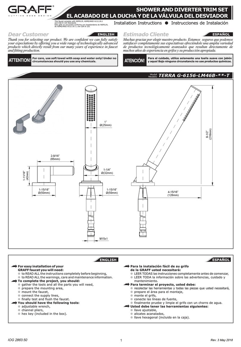
This faucet complies with NSF61/9, ASME/ANSI A112.18.1and CSA B 125 Standards.Este grifo se encuentra conforme con losestandares de NSF61/9,de ASME/ANSI A112.18.1 y de CSA B 125.Installation Instructions l Instrucciones de instalación LAVATORY FAUCETGRIFO DE LAVATORIO®6-11/32" (161mm)8" (203.2mm)
9-9/16" (243mm)6-3/8" (162mm)
6-11/32" (161mm)8" (203.2mm)
9-9/16" (243mm)6-3/8" (162mm)
8" (203.2mm)Ø1-11/32" (Ø34mm)OFFSET 1-1/16"(27mm)Ø1-11/32"(Ø34mm)Ø1-11/32"(Ø34mm)4" (101.6mm)HOT WATER INLETSupply tube - 3/8" O.D. (9.5 mm)ENTRADA DE AGUA CALIENTETuberia - 3/8" O.D. (9.5 mm)COLD WATER INLETSupply tube - 3/8" O.D. (9.5 mm)ENTRADA DE AGUA FRÍATuberia - 3/8" O.D. (9.5 mm)FIG. 112.1-L2.1-R3456.1-L6.1-R6.2-L6.2-R789101112131415161718192021222324252627282930
~
ESPANOLENGLISHCUERPOCABEZA CERÁMICA(se abre hacia la izquierda)CABEZA CERÁMICA(se abre hacia la derecha)ESPIGA DE EXTENSIÓNINSERTOR DE TEFLONCHAPAVOLANTE CRUZADO (H – agua caliente)VOLANTE CRUZADO (C – agua fría)MANILLA DE METAL (H – agua caliente)MANILLA DE METAL (C – agua fría)TORNILLOCUERPO SUPERIORTORNILLO SUJETADOREMPAQUETADURA DE ANILLOCASQUILLO DEL CAŃOCASQUILLO DE RESISTENCIACAŃOEMPAQUETADURAINWERTOR DEL AEREADORCUERPO DEL AEREADOREMPAQUETADURA DE ANILLOCONECTADOR ROSCADOCONTRATUERCAARANDELA CONICAARANDELA DE METALTUERCA DEL ACOPLADORVARILLA ELEVADORABASE DE LA VARILLA ELEVADORAARANDELAARANDELA DE METALTUERCACASQUILLOTUERCATUERCABODY OF FAUCETCERAMIC HEAD (counterclockwise opening)CERAMIC HEAD (clockwise opening)STEM EXTENSIONTEFLON INSERTSHROUDCROSS HANDLE (H – hot water) CROSS HANDLE (C – cold water)METAL HANDLE (H – hot water)METAL HANDLE (C – cold water)SCREWTOP BODYFASTENING SCREWO-RING SEALSPOUT SLEEVERESISTANCE SLEEVESPOUTSEALAERATOR INSERTBODY OF AERATORO-RINGTHREADED FERRULELOCKNUTCONE GASKETMETAL WASHERCOUPLING NUTLIFT RODLIFT ROD BASEWASHERMETAL WASHERNUTSLEEVENUTNUT76.2-L6.2-R6.1-L2.1-L6.1-R2.1-R5424131083029282726259118181919202021212222232337141516171211Loosen up the nuts (9).Soltar las tuercas (9).Insert the faucet into the fitting hole of the lavatory.Colocar el grifo dentro del agujero de fijación del lavatorio.1)1)Place faucet into position on lavatory. Make sure that the o-ring seals Luego colocar el grifo en la posición correcta en el lavatorio. (18) sit correctly in their own housing in the body of faucet (1).Asegurarse de que las empaquetaduras de anillo (18) asienten Check the faucet position and secure in place using the locknuts correctamente en sus propias cubiertas en del cuerpo del grifo (1).(20). Hand tighten only. Do not over-tighten.Verificar la posición del grifo y asegurla usando las contratuercas Tighten the nuts (9).(20). Ajustarlas sólo con la mano. No apretar demasiado.Apretar las tuercas (9).1)1) Si el fregadero no esta sellado, use el silicón sellante. If lavatory is uneven use silicone sealant.21 FAUCET INSTALLATION l INSTALACIÓN DEL GRIFO3DRAIN ASSEMBLY INSTALLATION l INSTALACIÓN DEL DRENAJE
~
ESPANOLENGLISHSee fig. 1Veá dis. 1LIFT ROD INSTALLATION l INSTALACIÓN DE LA VARILLA ELEVADORA282525252426292730FIG. 2.1FIG. 2.2FIG. 2.3See fig. 2.1 – 2.3Vea dis. 2.1 – 2.3Apply a bead of plumbers putty or other sealant to the underside Aplicar un glóbulo de masilla de plomero u otro empaque a la of the escutcheon according to the putty manufacturer's instructions.parte inferior del escudo de acuerdo con la instrucción del fabricante Unscrew the nut (30) with rubber sleeve (29) and the nut (28) de la masillafrom the shank of lift rod base. Remove metal washer (27) and the Desatornillar la tuerca (30) con casquillo de goma (29) y la washer (26).tuerca (28) del vástago de la base de la varilla elevadora. Remover Insert the lift rod base (25) through the mounting hole from arandela de metal (27) y la arandela (26).above.Insertar la base de la varilla elevadora (25) a través del agujero From the underside of the lavatory, slide the washer (26), metal colgante de arriba.washer (27), and nut (28) onto the escutcheon shank.De la parte inferior del lavatorio, deslizar la arandela (26), Securely tighten the nut (28) with a wrench. Do not overtighten.arandela de metal (27), y la tuerca (28) en el vástago del escudoRemove any excess putty or sealant.Apretar firmemente la tuerca (28) con la llave. No apretar Screw the nut (30) with rubber sleeve (29) on to the shank.demasiado fuerte.Insert the lift rod (24) into the hole of the base and tighten the Remover el exceso de masilla o empaque.nut (30) if needed.Atornillar la tuerca (30) con casquillo de goma al vástago.Insertar la varilla elevadora (24) en el agujero de la base y si es necesario, apretar la tuerca (30).ENGLISH
~
ESPANOLFIG. 3
~
ESPANOLENGLISH
PROTECTIVE CAPDRAIN PLUGDRAIN COLLARCOLLAR GASKETUNDER-BOWL GASKETWASHERFLANGED NUTWASHERDRAIN BODYDISCHARGE PIPESEALING WASHERBALL RODBALL ROD NUTADJUSTMENT PLATECLIPSCREW12345678910111213141516TAPA PROTECTORATAPÓN DE DRENAJECOLLAR DE DRENAJEEMPAQUETADURA SUPERIOREMPAQUETADURA INFERIORARANDELA DE MONTAJETUERCA DE MONTAJEARANDELA DE TUBOCUERPO DE DRENAJEPIPA DE DESCARGAARANDELA SELLADORAVARILLA DE BOLATUERCA DEL PIVOTEPLATO DE AJUSTAMIENTOBROCHETORNILLOLIFT ROD(fig.1, item 24 )Varilla elevadora(24 fig. 1)12345678910141112131516
~
ESPANOL
Desmontar las piezas del drenaje según lo demostrado en la dis. 5. Inserte la empaquetadura superior (4) y el tapon del drenaje (3) en el agujero del drenaje de un servicio. Colaque por debajo del lavatorio la empaquetadura inferior (5) en el collar del drenaje (3), la arandela (6) y tuerca de montaje (7)Coloque la empaquetadura inferior (5) correctamente debajo del servicio y entornille a tuerca de montaje (7) firmemente pero no apriete demasiado. Cerciorese de que la arandela de tubo (8) este en el cuerpo del drenaje (9) y entornille el cuerpo del drenaje (9) en el collar del drenaje (3) apriete solamente con la manoPreste atención en alinear el cuerpo del drenaje (9) de modo que el agujero horizontal del cuerpo del drenaje esté en el mismo plano que la varilla elevadora (dis.1, elem. 3). Apriete el cuerpo del drenaje (9) sobre el collar del drenaje (3) y apriete la tuerca de montaje (7). Inserte el tapón de drenaje (2) en el collar del drenaje (3).Quite el clip de la abrazadera de muelle (15) del varilla de bola (12); retire la tuerca del pivote (13) del cuerpo, tome hacia fuera el arandela selladora (11) a lo largo del varilla de bola (12) del extremo más.Inserte el arandela selladora (11) y el varilla de bola (12) en un agujero lateral del cuerpo del drenaje (9). Asegúrese de que el extremo de la barra va debajo de la cabeza del tornillo del tapón.Ajuste la tuerca del pivote (13) serciorandose de que el arandela selladora de la barra (11) y el varilla de bola (12) este instalado correctamente.Enrrollar la cinta de teflon para asegurar el pipa de descarga (10), monte colillo al cuerpo del drenaje (9).Levante el tapón de renaje (2) a la posición de abierto, moviendo el varilla de bola (12) hacia abajo.Inserte la varilla elevadora (dis.1, elem. 24) por el agujero en el grifo (dis. 1, elem.1) y inserte el plato de ajustamiento (14). Ajuste a la altura apropiada y apriete el tornillo (16).Elija la posición del varilla de bola (12) en uno de los agujeros del plato de ajustamiento (14). El varilla de bola (12) a través de la broche (15) y levante el plato de ajustamiento (14) y despues el segundo brazo de la broche (15).Intente cerrar con el tapón de drenaje (2) tirando de la varilla de elevación. Si no es posible, haga las correcciones de la posición del plato de ajustamiento (14) y de la barra horizontal del el varilla de bola (12).d
ENGLISH
Dismantle the drain assembly to the parts shown on fig. 5. Insert collar gasket (4) and drain collar (3) into drain hole of a lavatory. From underneath the lavatory slip under-bowl gasket (5) into drain collar (3), washer (6) and flanged nut (7).Position under-bowl gasket (5) correctly under the lavatory and screw flanged nut (7) firmly but do not overtighten.Make sure washer (8) is inside drain body (9) and screw drain body (9) onto drain collar (3) hand tighten only.Pay attention to align the drain body (9) so that the horizontal hole of drain body will be in the same plane as a lift rod (24 fig.1). Tighten drain body (9) onto drain collar (3) and tighten the flanged nut (7).Insert drain plug (2) into drain collar (3).Remove clip (15) from ball rod (12); undo a ball rod nut (13) from body, take out sealing washer (11) from a nut and push the nut forward over ball rod (12) from the longer end with the thread facing a ball.Insert the sealing washer (11) and the ball rod (12) into a side hole of drain body (9). Make sure that the rod ending goes under the plug screw head.Tighten ball rod nut (13) making sure that the ball rod seat (11) and ball rod (12) are properly installed.Add Teflon tape to tail tube (10), and mount tail tube to drain body (9).Lift the drain plug (2) to an open position, by lowering the horizontal ball rod (12) down.Insert lift rod (3 fig.1) down through spout (1 fig.1) and top of lift rod strap (14). Adjust to proper height and tighten screw (16).Choose the position of horizontal ball rod (12) in one of the holes in lift rod strap (14). Insert horizontal ball rod (12) through one arm of spring clip (15) and lift rod strap (14) and then second arm of spring clip (15).Try if a drain plug (2) closes the drain by pulling the lift rod. If not, make corrections of position of lift rod strap (14) and horizontal ball rod (12).4MAKE CONNECTIONS TO WATER LINES l CONECCION A LAS FUENTES DE AGUASee fig. 1Veá dis. 1Use mounting set to 3/8” copper tubes consisting of cone gaskets (21), metal washers Use un completo de montaje para tuberias de Cu de 3/8” que consisten en (22) and coupling nuts (23).empaquetaduras (21), arandelas de metal (22) y uniones (23).Use adjustable wrench when tightening. Do not overtighten. Utilice llaves ajustables cunado necesite ajustar alguna pieza. No ajuste demasiado.
~
ESPANOLENGLISH
See fig. 1Veá dis. 1Remove body of aerator (17), aerator insert (16) and washer (15) and turn Quite el aereador (17), el relleno del aerador (16) y la arandela (15) y gire las faucet lever handles all the way on.manillas a la posición de abierto.1)Open the hot and cold water supply valves and flush water lines for 15 seconds Abra las válvulas de agua caliente y fría y deje enjuagar las tuberias por 15 1)Turn the hot and cold handles off.segundos .Check all connections at arrows for leaks. Re-tighten if necessary, but do not Cierre las manillas de agua fria y caliente.overtighten.Compruebe todas las conexiones para saber si hay fuga de agua. Vuelva a Next replace washer (15), aerator insert (16) and body of aerator (17). Hand apretar en caso de necesidad, pero no apriete demasiado.tighten only.Seguidamente remplace la arandela (15), el relleno del aerador (16) y el aereador (17). Ajuste solamente con la mano.1)1) IMPORTANT:This flushes away any debris that could cause damage to internal IMPORTANTE:Esto limpia las tuberias con un chorro de agua de todo residuo que parts.podría causar dańo a las piezas internas.CONGRATULATIONS! Your installation is now complete!FELICIDADES! Su instalación está completa!5AFTER INSTALLATION BEFORE USE l DESPUÉS DE LA INSTALACIÓN - ANTES DEL USO
~
ESPANOLENGLISH
6OPERATING INSTRUCTIONS l LA DESCRIPCIÓN DEL FUNCIONAMIENTOLevers (cross handles) are used to open and regulate the water flow. Full flow is Para abrir la salida y la regulación del flujo del agua sirven las palancas (los volantes oobtained by turning the lever (cross handle) through 90(the cold water tap on the cruzados). La apertura total sucede al tornar la palanca (el volante cruzado) por el oright goes clockwise, the hot water tap on the left counterclockwise). The intensity ángulo de 90 (de acuerdo con el movimiento de las manillas del reloj la palanca del ooof the water flow is regulated by positions between 0÷90.agua fría colocada en el lado derecho, en contrario del movimiento de las manillas del reloj la palanca del agua caliente colocada en el lado izquierdo). La regulación de oola intensidad del flujo de agua sucede en las posiciones 0÷90.
~
ESPANOLENGLISH
7
CARE AND MAINTENANCE l CUIDADO Y MANTENIMIENTO
Your Graff faucet is designed and engineered in accordance with the Su grifo de la Graff esta diseńado y dirigido acuerdo con los highest quality and performance standards. Be sure not to damage estándares de funcionamiento y calidad más altos. Este seguro no the finish during installation. Care should be given to the cleaning of dańar las terminaciones del grifo durante la instalación. Cuide el this product. Although its finish is extremely durable, it can be producto manteniendolo siempre limpio. Aunque su acabado es damaged by harsh abrasives or polish. Never use abrasive extremadamente durable, puede ser dańado por los abrasivos o cleaners, acids, solvents, etc. to clean any Graff product. To pulientes ásperos. Nunca utilice limpiadores abrasivos, ácidos, clean, simply wipe gently with a damp cloth and blot dry with solventes, el etc. para limpiar cualquier producto de la Graff. a soft towel.Para limpiar, simplemente use un pańo húmedo y seque con una toalla suave.
~
ESPANOLENGLISH
~
ESPANOLENGLISH
WARRANTY l GARANTÍA
Warranty conditions and warranty registration card are outlined on a Las condiciones de la garantía y la tarjeta del registro de la garantía separate sheet.se encuentran en una pagina separada.All dimensions and drawings are for reference only. For details, please refer to actual products.Todas las dimensiones y dibujos sirven únicamente de referencia. Para consultar detalles, ver los productos.
This faucet complies with NSF61/9, ASME/ANSI A112.18.1and CSA B 125 Standards.Este grifo se encuentra conforme con losestandares de NSF61/9,de ASME/ANSI A112.18.1 y de CSA B 125.Installation Instructions l Instrucciones de instalación LAVATORY FAUCETGRIFO DE LAVATORIO
Rev. 3 July 2016
For easy installation of yourPara la instalación fácil de su grifoGRAFF faucet you will need:de la GRAFF usted necesitará: to READ ALL the instructions completely before beginning,LEER TODAS las instrucciones completamente antes de comenzar, to READ ALL the warnings, care and maintenance information.LEER TODA la información sobre las advertencias,To complete the project, you should: cuidado y mantenimiento.gather the tools and all the parts you will need,Para terminar el proyecto, usted debe:prepare the mounting area,recolectar las herramientas y todas las piezas que usted necesitará,mount the faucet,prepare el área para el montaje,connect the supply lines,monte el grifo,finally test and flush the faucet.conecte las líneas de fuente,You should have the following tools:finalmente pruebe y limpie el grifo con un chorro de agua.Usted debe tener las herramientas siguientes:flat blade screwdriver,destornillador plano,adjustable wrench,llave ajustable,channel pliers,alicates acanalados,hex key (included in the box),®llave de tuerca hexagonal (incluido en la caja),Teflon tape,®cinta adhesiva de Teflón,plumbers putty or caulking (silicone).masilla o silicona.l l l l l l l l l l l l l l l l l l l l l l l l l l ENGLISH
~
ESPANOL1SET-UP DIAGRAM l DIAGRAMA DE INSTALACIÓN REMOVE OLD FAUCETTurn off the water supplies (hot and cold water).Disconnect supply lines and remove old faucet.Clean the lavatory surface of putty, dirt., etc.BEFORE INSTALLINGBefore installing the faucet, it is good to rinse the supply pipelines in order to do away with the dirt residue.We recommend installing the filter taps.QUITE EL GRIFO VIEJOCierre las llaves de suministro de agua (agua caliente y fría).Desconecte las líneas de suministro y quite el grifo viejo.Limpie la superficie del lavatorio de la masilla, suciedad, etc.ANTES DE LA INSTALACIÓNAntes de instalar el grifo, es bueno enjugar las tuberías suministro para eliminar residuos.Recomendamos el instalar los tapones de filtro.ll l l l l l l l lENGLISH
~
ESPANOLIOG 2278.803IOG 2278.80Rev. 1 October 20065
IOG 2278.80Rev. 1 October 20064
IOG 2278.80Rev. 1 October 20062IOG 2278.80Rev. 1 October 20061ModelModeloCanterbury Collection 3800- LC1ModelModeloCanterbury Collection 3800-C2FLOW RATE INFORMATIONINFORMACIÓN DE INTENSIDAD DE FLUJO Max flow rate 2.2 gpm (8.3 l/min.) at 60 psi (4 bar).Flujo máximo 2.2 gpm (8.3 l/min.) con 60 psi (4 bar).ENGLISH
~
ESPANOLDear CustomerEstimado ClienteThank you for selecting our product. We are confident we can fully satisfy Muchas gracias por elegir nuestro producto. Estamos seguros que podemos satisfacer completamente sus expectativas ofreciéndole una amplia variedad your expectations by offering you a wide range of technologically advanced products which directly result from our many years of experience in faucet de productos tecnológicamente avanzados que resultan directamente de and fitting production.muchos años de experiencia en grifos y su producción apropiada.
ENGLISH
~
ESPANOL
For care, use soft towel with soap and water only! Under nocircumstances should you use any chemicals. For faucets with ORB (oil rubbed bronze) finish please be extra careful not to damage, scuff or ruin the finish during the installation and cleaning!ATTENTION!ATENCIÓN!Para el cuidado, utilice solamente una toalla suave con jabón y aqua! Bajo ninguna circunstancia no use productos químicos. Con los grifos de acabado ORB (bronce frotado con aceite) hay que tener un cuidado especial para no dańar, arańar o destruir el acabado durante su instalación o limpieza! This faucet complies with NSF61/9, ASME/ANSI A112.18.1and CSA B 125 Standards.Este grifo se encuentra conforme con losestandares de NSF61/9,de ASME/ANSI A112.18.1 y de CSA B 125.Installation Instructions l Instrucciones de instalación LAVATORY FAUCETGRIFO DE LAVATORIO®
This faucet complies with NSF61/9, ASME/ANSI A112.18.1and CSA B 125 Standards.Este grifo se encuentra conforme con losestandares de NSF61/9,de ASME/ANSI A112.18.1 y de CSA B 125.Installation Instructions l Instrucciones de instalación LAVATORY FAUCETGRIFO DE LAVATORIO®
This faucet complies with NSF61/9, ASME/ANSI A112.18.1and CSA B 125 Standards.Este grifo se encuentra conforme con losestandares de NSF61/9,de ASME/ANSI A112.18.1 y de CSA B 125.Installation Instructions l Instrucciones de instalación LAVATORY FAUCETGRIFO DE LAVATORIO®This faucet complies with NSF61/9, ASME/ANSI A112.18.1and CSA B 125 Standards.Este grifo se encuentra conforme con losestandares de NSF61/9,de ASME/ANSI A112.18.1 y de CSA B 125.Installation Instructions l Instrucciones de instalación LAVATORY FAUCETGRIFO DE LAVATORIO®6-11/32" (161mm)8" (203.2mm)
9-9/16" (243mm)6-3/8" (162mm)
6-11/32" (161mm)8" (203.2mm)
9-9/16" (243mm)6-3/8" (162mm)
8" (203.2mm)Ø1-11/32" (Ø34mm)OFFSET 1-1/16"(27mm)Ø1-11/32"(Ø34mm)Ø1-11/32"(Ø34mm)4" (101.6mm)HOT WATER INLETSupply tube - 3/8" O.D. (9.5 mm)ENTRADA DE AGUA CALIENTETuberia - 3/8" O.D. (9.5 mm)COLD WATER INLETSupply tube - 3/8" O.D. (9.5 mm)ENTRADA DE AGUA FRÍATuberia - 3/8" O.D. (9.5 mm)FIG. 112.1-L2.1-R3456.1-L6.1-R6.2-L6.2-R789101112131415161718192021222324252627282930
~
ESPANOLENGLISHCUERPOCABEZA CERÁMICA(se abre hacia la izquierda)CABEZA CERÁMICA(se abre hacia la derecha)ESPIGA DE EXTENSIÓNINSERTOR DE TEFLONCHAPAVOLANTE CRUZADO (H – agua caliente)VOLANTE CRUZADO (C – agua fría)MANILLA DE METAL (H – agua caliente)MANILLA DE METAL (C – agua fría)TORNILLOCUERPO SUPERIORTORNILLO SUJETADOREMPAQUETADURA DE ANILLOCASQUILLO DEL CAŃOCASQUILLO DE RESISTENCIACAŃOEMPAQUETADURAINWERTOR DEL AEREADORCUERPO DEL AEREADOREMPAQUETADURA DE ANILLOCONECTADOR ROSCADOCONTRATUERCAARANDELA CONICAARANDELA DE METALTUERCA DEL ACOPLADORVARILLA ELEVADORABASE DE LA VARILLA ELEVADORAARANDELAARANDELA DE METALTUERCACASQUILLOTUERCATUERCABODY OF FAUCETCERAMIC HEAD (counterclockwise opening)CERAMIC HEAD (clockwise opening)STEM EXTENSIONTEFLON INSERTSHROUDCROSS HANDLE (H – hot water) CROSS HANDLE (C – cold water)METAL HANDLE (H – hot water)METAL HANDLE (C – cold water)SCREWTOP BODYFASTENING SCREWO-RING SEALSPOUT SLEEVERESISTANCE SLEEVESPOUTSEALAERATOR INSERTBODY OF AERATORO-RINGTHREADED FERRULELOCKNUTCONE GASKETMETAL WASHERCOUPLING NUTLIFT RODLIFT ROD BASEWASHERMETAL WASHERNUTSLEEVENUTNUT76.2-L6.2-R6.1-L2.1-L6.1-R2.1-R5424131083029282726259118181919202021212222232337141516171211Loosen up the nuts (9).Soltar las tuercas (9).Insert the faucet into the fitting hole of the lavatory.Colocar el grifo dentro del agujero de fijación del lavatorio.1)1)Place faucet into position on lavatory. Make sure that the o-ring seals Luego colocar el grifo en la posición correcta en el lavatorio. (18) sit correctly in their own housing in the body of faucet (1).Asegurarse de que las empaquetaduras de anillo (18) asienten Check the faucet position and secure in place using the locknuts correctamente en sus propias cubiertas en del cuerpo del grifo (1).(20). Hand tighten only. Do not over-tighten.Verificar la posición del grifo y asegurla usando las contratuercas Tighten the nuts (9).(20). Ajustarlas sólo con la mano. No apretar demasiado.Apretar las tuercas (9).1)1) Si el fregadero no esta sellado, use el silicón sellante. If lavatory is uneven use silicone sealant.21 FAUCET INSTALLATION l INSTALACIÓN DEL GRIFO 3DRAIN ASSEMBLY INSTALLATION l INSTALACIÓN DEL DRENAJE
~
ESPANOLENGLISHSee fig. 1Veá dis. 1LIFT ROD INSTALLATION l INSTALACIÓN DE LA VARILLA ELEVADORA282525252426292730FIG. 2.1FIG. 2.2FIG. 2.3See fig. 2.1 – 2.3Vea dis. 2.1 – 2.3Apply a bead of plumbers putty or other sealant to the underside Aplicar un glóbulo de masilla de plomero u otro empaque a la of the escutcheon according to the putty manufacturer's instructions.parte inferior del escudo de acuerdo con la instrucción del fabricante Unscrew the nut (30) with rubber sleeve (29) and the nut (28) de la masillafrom the shank of lift rod base. Remove metal washer (27) and the Desatornillar la tuerca (30) con casquillo de goma (29) y la washer (26).tuerca (28) del vástago de la base de la varilla elevadora. Remover Insert the lift rod base (25) through the mounting hole from arandela de metal (27) y la arandela (26).above.Insertar la base de la varilla elevadora (25) a través del agujero From the underside of the lavatory, slide the washer (26), metal colgante de arriba.washer (27), and nut (28) onto the escutcheon shank.De la parte inferior del lavatorio, deslizar la arandela (26), Securely tighten the nut (28) with a wrench. Do not overtighten.arandela de metal (27), y la tuerca (28) en el vástago del escudoRemove any excess putty or sealant.Apretar firmemente la tuerca (28) con la llave. No apretar Screw the nut (30) with rubber sleeve (29) on to the shank.demasiado fuerte.Insert the lift rod (24) into the hole of the base and tighten the Remover el exceso de masilla o empaque.nut (30) if needed.Atornillar la tuerca (30) con casquillo de goma al vástago.Insertar la varilla elevadora (24) en el agujero de la base y si es necesario, apretar la tuerca (30).ENGLISH
~
ESPANOL FIG. 3
~
ESPANOLENGLISH
PROTECTIVE CAPDRAIN PLUGDRAIN COLLARCOLLAR GASKETUNDER-BOWL GASKETWASHERFLANGED NUTWASHERDRAIN BODYDISCHARGE PIPESEALING WASHERBALL RODBALL ROD NUTADJUSTMENT PLATECLIPSCREW12345678910111213141516TAPA PROTECTORATAPÓN DE DRENAJECOLLAR DE DRENAJEEMPAQUETADURA SUPERIOREMPAQUETADURA INFERIORARANDELA DE MONTAJETUERCA DE MONTAJEARANDELA DE TUBOCUERPO DE DRENAJEPIPA DE DESCARGAARANDELA SELLADORAVARILLA DE BOLATUERCA DEL PIVOTEPLATO DE AJUSTAMIENTOBROCHETORNILLOLIFT ROD(fig.1, item 24 )Varilla elevadora(24 fig. 1)12345678910141112131516
~
ESPANOL
Desmontar las piezas del drenaje según lo demostrado en la dis. 5. Inserte la empaquetadura superior (4) y el tapon del drenaje (3) en el agujero del drenaje de un servicio. Colaque por debajo del lavatorio la empaquetadura inferior (5) en el collar del drenaje (3), la arandela (6) y tuerca de montaje (7)Coloque la empaquetadura inferior (5) correctamente debajo del servicio y entornille a tuerca de montaje (7) firmemente pero no apriete demasiado. Cerciorese de que la arandela de tubo (8) este en el cuerpo del drenaje (9) y entornille el cuerpo del drenaje (9) en el collar del drenaje (3) apriete solamente con la manoPreste atención en alinear el cuerpo del drenaje (9) de modo que el agujero horizontal del cuerpo del drenaje esté en el mismo plano que la varilla elevadora (dis.1, elem. 3). Apriete el cuerpo del drenaje (9) sobre el collar del drenaje (3) y apriete la tuerca de montaje (7). Inserte el tapón de drenaje (2) en el collar del drenaje (3).Quite el clip de la abrazadera de muelle (15) del varilla de bola (12); retire la tuerca del pivote (13) del cuerpo, tome hacia fuera el arandela selladora (11) a lo largo del varilla de bola (12) del extremo más.Inserte el arandela sel ladora (11) y el varilla de bola (12) en un agujero lateral del cuerpo del drenaje (9). Asegúrese de que el extremo de la barra va debajo de la cabeza del tornillo del tapón.Ajuste la tuerca del pivote (13) serciorandose de que el arandela selladora de la barra (11) y el varilla de bola (12) este instalado correctamente.Enrrollar la cinta de teflon para asegurar el pipa de descarga (10), monte colillo al cuerpo del drenaje (9).Levante el tapón de renaje (2) a la posición de abierto, moviendo el varilla de bola (12) hacia abajo.Inserte la varilla elevadora (dis.1, elem. 24) por el agujero en el grifo (dis. 1, elem.1) y inserte el plato de ajustamiento (14). Ajuste a la altura apropiada y apriete el tornillo (16).Elija la posición del varilla de bola (12) en uno de los agujeros del plato de ajustamiento (14). El varilla de bola (12) a través de la broche (15) y levante el plato de ajustamiento (14) y despues el segundo brazo de la broche (15).Intente cerrar con el tapón de drenaje (2) tirando de la varilla de elevación. Si no es posible, haga las correcciones de la posición del plato de ajustamiento (14) y de la barra horizontal del el varilla de bola (12).d
ENGLISH
Dismantle the drain assembly to the parts shown on fig. 5. Insert collar gasket (4) and drain collar (3) into drain hole of a lavatory. From underneath the lavatory slip under-bowl gasket (5) into drain collar (3), washer (6) and flanged nut (7).Position under-bowl gasket (5) correctly under the lavatory and screw flanged nut (7) firmly but do not overtighten.Make sure washer (8) is inside drain body (9) and screw drain body (9) onto drain collar (3) hand tighten only.Pay attention to align the drain body (9) so that the horizontal hole of drain body will be in the same plane as a lift rod (24 fig.1). Tighten drain body (9) onto drain collar (3) and tighten the flanged nut (7).Insert drain plug (2) into drain collar (3).Remove clip (15) from ball rod (12); undo a ball rod nut (13) from body, take out sealing washer (11) from a nut and push the nut forward over ball rod (12) from the longer end with the thread facing a ball.Insert the sealing washer (11) and the ball rod (12) into a side hole of drain body (9). Make sure that the rod ending goes under the plug screw head.Tighten ball rod nut (13) making sure that the ball rod seat (11) and ball rod (12) are properly installed.Add Teflon tape to tail tube (10), and mount tail tube to drain body (9).Lift the drain plug (2) to an open position, by lowering the horizontal ball rod (12) down.Insert lift rod (3 fig.1) down through spout (1 fig.1) and top of lift rod strap (14). Adjust to proper height and tighten screw (16).Choose the position of horizontal ball rod (12) in one of the holes in lift rod strap (14). Insert horizontal ball rod (12) through one arm of spring clip (15) and lift rod strap (14) and then second arm of spring clip (15).Try if a drain plug (2) closes the drain by pulling the lift rod. If not, make corrections of position of lift rod strap (14) and horizontal ball rod (12).4MAKE CONNECTIONS TO WATER LINES l CONECCION A LAS FUENTES DE AGUASee fig. 1Veá dis. 1Use mounting set to 3/8” copper tubes consisting of cone gaskets (21), metal washers Use un completo de montaje para tuberias de Cu de 3/8” que consisten en (22) and coupling nuts (23).empaquetaduras (21), arandelas de metal (22) y uniones (23).Use adjustable wrench when tightening. Do not overtighten. Utilice llaves ajustables cunado necesite ajustar alguna pieza. No ajuste demasiado.
~
ESPANOLENGLISH
See fig. 1Veá dis. 1Remove body of aerator (17), aerator insert (16) and washer (15) and turn Quite el aereador (17), el relleno del aerador (16) y la arandela (15) y gire las faucet lever handles all the way on.manillas a la posición de abierto.1)Open the hot and cold water supply valves and flush water lines for 15 seconds Abra las válvulas de agua caliente y fría y deje enjuagar las tuberias por 15 1)Turn the hot and cold handles off.segundos .Check all connections at arrows for leaks. Re-tighten if necessary, but do not Cierre las manillas de agua fria y caliente.overtighten.Compruebe todas las conexiones para saber si hay fuga de agua. Vuelva a Next replace washer (15), aerator insert (16) and body of aerator (17). Hand apretar en caso de necesidad, pero no apriete demasiado.tighten only.Seguidamente remplace la arandela (15), el relleno del aerador (16) y el aereador (17). Ajuste solamente con la mano.1)1) IMPORTANT:This flushes away any debris that could cause damage to internal IMPORTANTE:Esto limpia las tuberias con un chorro de agua de todo residuo que parts.podría causar dańo a las piezas internas.CONGRATULATIONS! Your installation is now complete!FELICIDADES! Su instalación está completa!5AFTER INSTALLATION BEFORE USE l DESPUÉS DE LA INSTALACIÓN - ANTES DEL USO
~
ESPANOLENGLISH
6OPERATING INSTRUCTIONS l LA DESCRIPCIÓN DEL FUNCIONAMIENTOLevers (cross handles) are used to open and regulate the water flow. Full flow is Para abrir la salida y la regulación del flujo del agua sirven las palancas (los volantes oobtained by turning the lever (cross handle) through 90(the cold water tap on the cruzados). La apertura total sucede al tornar la palanca (el volante cruzado) por el oright goes clockwise, the hot water tap on the left counterclockwise). The intensity ángulo de 90 (de acuerdo con el movimiento de las manillas del reloj la palanca del ooof the water flow is regulated by positions between 0÷90.agua fría colocada en el lado derecho, en contrario del movimiento de las manillas del reloj la palanca del agua caliente colocada en el lado izquierdo). La regulación de oola intensidad del flujo de agua sucede en las posiciones 0÷90.
~
ESPANOLENGLISH
7
CARE AND MAINTENANCE l CUIDADO Y MANTENIMIENTO
Your Graff faucet is designed and engineered in accordance with the Su grifo de la Graff esta diseńado y dirigido acuerdo con los highest quality and performance standards. Be sure not to damage estándares de funcionamiento y calidad más altos. Este seguro no the finish during installation. Care should be given to the cleaning of dańar las terminaciones del grifo durante la instalación. Cuide el this product. Although its finish is extremely durable, it can be producto manteniendolo siempre limpio. Aunque su acabado es damaged by harsh abrasives or polish. Never use abrasive extremadamente durable, puede ser dańado por los abrasivos o cleaners, acids, solvents, etc. to clean any Graff product. To pulientes ásperos. Nunca utilice limpiadores abrasivos, ácidos, clean, simply wipe gently with a damp cloth and blot dry with solventes, el etc. para limpiar cualquier producto de la Graff. a soft towel.Para limpiar, simplemente use un pańo húmedo y seque con una toalla suave.
~
ESPANOLENGLISH
~
ESPANOLENGLISH
WARRANTY l GARANTÍA
Warranty conditions and warranty registration card are outlined on a Las condiciones de la garantía y la tarjeta del registro de la garantía separate sheet.se encuentran en una pagina separada.All dimensions and drawings are for reference only. For details, please refer to actual products.Todas las dimensiones y dibujos sirven únicamente de referencia. Para consultar detalles, ver los productos.
This faucet complies with NSF61/9, ASME/ANSI A112.18.1and CSA B 125 Standards.Este grifo se encuentra conforme con losestandares de NSF61/9,de ASME/ANSI A112.18.1 y de CSA B 125.Installation Instructions l Instrucciones de instalación LAVATORY FAUCETGRIFO DE LAVATORIO
Rev. 3 July 2016
For easy installation of yourPara la instalación fácil de su grifoGRAFF faucet you will need:de la GRAFF usted necesitará: to READ ALL the instructions completely before beginning,LEER TODAS las instrucciones completamente antes de comenzar, to READ ALL the warnings, care and maintenance information.LEER TODA la información sobre las advertencias,To complete the project, you should: cuidado y mantenimiento.gather the tools and all the parts you will need,Para terminar el proyecto, usted debe:prepare the mounting area,recolectar las herramientas y todas las piezas que usted necesitará,mount the faucet,prepare el área para el montaje,connect the supply lines,monte el grifo,finally test and flush the faucet.conecte las líneas de fuente,You should have the following tools:finalmente pruebe y limpie el grifo con un chorro de agua.Usted debe tener las herramientas siguientes:flat blade screwdriver,destornillador plano,adjustable wrench,llave ajustable,channel pliers,alicates acanalados,hex key (included in the box),®llave de tuerca hexagonal (incluido en la caja),Teflon tape,®cinta adhesiva de Teflón,plumbers putty or caulking (silicone).masilla o silicona.l l l l l l l l l l l l l l l l l l l l l l l l l l ENGLISH
~
ESPANOL1SET-UP DIAGRAM l DIAGRAMA DE INSTALACIÓN REMOVE OLD FAUCETTurn off the water supplies (hot and cold water).Disconnect supply lines and remove old faucet.Clean the lavatory surface of putty, dirt., etc.BEFORE INSTALLINGBefore installing the faucet, it is good to rinse the supply pipelines in order to do away with the dirt residue.We recommend installing the filter taps.QUITE EL GRIFO VIEJOCierre las llaves de suministro de agua (agua caliente y fría).Desconecte las líneas de suministro y quite el grifo viejo.Limpie la superficie del lavatorio de la masilla, suciedad, etc.ANTES DE LA INSTALACIÓNAntes de instalar el grifo, es bueno enjugar las tuberías suministro para eliminar residuos.Recomendamos el instalar los tapones de filtro.ll l l l l l l l lENGLISH
~
ESPANOLIOG 2278.80Rev. 1 October 20063IOG 2278.80Rev. 1 October 20065
IOG 2278.804
IOG 2278.80Rev. 1 October 20062IOG 2278.80Rev. 1 October 20061ModelModeloCanterbury Collection 3800-LC1ModelModeloCanterbury Collection 3800-C2FLOW RATE INFORMATIONINFORMACIÓN DE INTENSIDAD DE FLUJO Max flow rate 2.2 gpm (8.3 l/min.) at 60 psi (4 bar).Flujo máximo 2.2 gpm (8.3 l/min.) con 60 psi (4 bar).ENGLISH
~
ESPANOLDear CustomerEstimado ClienteThank you for selecting our product. We are confident we can fully satisfy Muchas gracias por elegir nuestro producto. Estamos seguros que podemos satisfacer completamente sus expectativas ofreciéndole una amplia variedad your expectations by offering you a wide range of technologically advanced products which directly result from our many years of experience in faucet de productos tecnológicamente avanzados que resultan directamente de and fitting production.muchos años de experiencia en grifos y su producción apropiada.
ENGLISH
~
ESPANOL
For care, use soft towel with soap and water only! Under nocircumstances should you use any chemicals. For faucets with ORB (oil rubbed bronze) finish please be extra careful not to damage, scuff or ruin the finish during the installation and cleaning!ATTENTION!ATENCIÓN!Para el cuidado, utilice solamente una toalla suave con jabón y aqua! Bajo ninguna circunstancia no use productos químicos. Con los grifos de acabado ORB (bronce frotado con aceite) hay que tener un cuidado especial para no dańar, arańar o destruir el acabado durante su instalación o limpieza! This faucet complies with NSF61/9, ASME/ANSI A112.18.1and CSA B 125 Standards.Este grifo se encuentra conforme con losestandares de NSF61/9,de ASME/ANSI A112.18.1 y de CSA B 125.Installation Instructions l Instrucciones de instalación LAVATORY FAUCETGRIFO DE LAVATORIO®This faucet complies with NSF61/9, ASME/ANSI A112.18.1and CSA B 125 Standards.Este grifo se encuentra conforme con losestandares de NSF61/9,de ASME/ANSI A112.18.1 y de CSA B 125.Installation Instructions l Instrucciones de instalación LAVATORY FAUCETGRIFO DE LAVATORIO®
This faucet complies with NSF61/9, ASME/ANSI A112.18.1and CSA B 125 Standards.Este grifo se encuentra conforme con losestandares de NSF61/9,de ASME/ANSI A112.18.1 y de CSA B 125.Installation Instructions l Instrucciones de instalación LAVATORY FAUCETGRIFO DE LAVATORIO®This faucet complies with NSF61/9, ASME/ANSI A112.18.1and CSA B 125 Standards.Este grifo se encuentra conforme con losestandares de NSF61/9,de ASME/ANSI A112.18.1 y de CSA B 125.Installation Instructions l Instrucciones de instalación LAVATORY FAUCETGRIFO DE LAVATORIO®6-11/32" (161mm)8" (203.2mm)
9-9/16" (243mm)6-3/8" (162mm)
6-11/32" (161mm)8" (203.2mm)
9-9/16" (243mm)6-3/8" (162mm)
8" (203.2mm)Ø1-11/32" (Ø34mm)OFFSET 1-1/16"(27mm)Ø1-11/32"(Ø34mm)Ø1-11/32"(Ø34mm)4" (101.6mm)HOT WATER INLETSupply tube - 3/8" O.D. (9.5 mm)ENTRADA DE AGUA CALIENTETuberia - 3/8" O.D. (9.5 mm)COLD WATER INLETSupply tube - 3/8" O.D. (9.5 mm)ENTRADA DE AGUA FRÍATuberia - 3/8" O.D. (9.5 mm)FIG. 112.1-L2.1-R3456.1-L6.1-R6.2-L6.2-R789101112131415161718192021222324252627282930
~
ESPANOLENGLISHCUERPOCABEZA CERÁMICA(se abre hacia la izquierda)CABEZA CERÁMICA(se abre hacia la derecha)ESPIGA DE EXTENSIÓNINSERTOR DE TEFLONCHAPAVOLANTE CRUZADO (H – agua caliente)VOLANTE CRUZADO (C – agua fría)MANILLA DE METAL (H – agua caliente)MANILLA DE METAL (C – agua fría)TORNILLOCUERPO SUPERIORTUERCATORNILLO SUJETADOREMPAQUETADURA DE ANILLOCASQUILLO DEL CAŃOCASQUILLO DE RESISTENCIACAŃOEMPAQUETADURAINWERTOR DEL AEREADORCUERPO DEL AEREADOREMPAQUETADURA DE ANILLOCONECTADOR ROSCADOCONTRATUERCAARANDELA CONICAARANDELA DE METALTUERCA DEL ACOPLADORVARILLA ELEVADORABASE DE LA VARILLA ELEVADORAARANDELAARANDELA DE METALTUERCACASQUILLOTUERCABODY OF FAUCETCERAMIC HEAD (counterclockwise opening)CERAMIC HEAD (clockwise opening)STEM EXTENSIONTEFLON INSERTSHROUDCROSS HANDLE (H – hot water) CROSS HANDLE (C – cold water)METAL HANDLE (H – hot water)METAL HANDLE (C – cold water)SCREWTOP BODYNUTFASTENING SCREWO-RING SEALSPOUT SLEEVERESISTANCE SLEEVESPOUTSEALAERATOR INSERTBODY OF AERATORO-RINGTHREADED FERRULELOCKNUTCONE GASKETMETAL WASHERCOUPLING NUTLIFT RODLIFT ROD BASEWASHERMETAL WASHERNUTSLEEVENUT76.2-L6.2-R6.1-L2.1-L6.1-R2.1-R5424131083029282726259118181919202021212222232337141516171211Loosen up the nuts (9).Soltar las tuercas (9).Insert the faucet into the fitting hole of the lavatory.Colocar el grifo dentro del agujero de fijación del lavatorio.1)1)Place faucet into position on lavatory. Make sure that the o-ring seals Luego colocar el grifo en la posición correcta en el lavatorio. (18) sit correctly in their own housing in the body of faucet (1).Asegurarse de que las empaquetaduras de anillo (18) asienten Check the faucet position and secure in place using the locknuts correctamente en sus propias cubiertas en del cuerpo del grifo (1).(20). Hand tighten only. Do not over-tighten.Verificar la posición del grifo y asegurla usando las contratuercas Tighten the nuts (9).(20). Ajustarlas sólo con la mano. No apretar demasiado.Apretar las tuercas (9).1)1) Si el fregadero no esta sellado, use el silicón sellante. If lavatory is uneven use silicone sealant.21 FAUCET INSTALLATION l INSTALACIÓN DEL GRIFO 3DRAIN ASSEMBLY INSTALLATION l INSTALACIÓN DEL DRENAJE
~
ESPANOLENGLISHSee fig. 1Veá dis. 1LIFT ROD INSTALLATION l INSTALACIÓN DE LA VARILLA ELEVADORA282525252426292730FIG. 2.1FIG. 2.2FIG. 2.3See fig. 2.1 – 2.3Vea dis. 2.1 – 2.3Apply a bead of plumbers putty or other sealant to the underside Aplicar un glóbulo de masilla de plomero u otro empaque a la of the escutcheon according to the putty manufacturer's instructions.parte inferior del escudo de acuerdo con la instrucción del fabricante Unscrew the nut (30) with rubber sleeve (29) and the nut (28) de la masillafrom the shank of lift rod base. Remove metal washer (27) and the Desatornillar la tuerca (30) con casquillo de goma (29) y la washer (26).tuerca (28) del vástago de la base de la varilla elevadora. Remover Insert the lift rod base (25) through the mounting hole from arandela de metal (27) y la arandela (26).above.Insertar la base de la varilla elevadora (25) a través del agujero From the underside of the lavatory, slide the washer (26), metal colgante de arriba.washer (27), and nut (28) onto the escutcheon shank.De la parte inferior del lavatorio, deslizar la arandela (26), Securely tighten the nut (28) with a wrench. Do not overtighten.arandela de metal (27), y la tuerca (28) en el vástago del escudoRemove any excess putty or sealant.Apretar firmemente la tuerca (28) con la llave. No apretar Screw the nut (30) with rubber sleeve (29) on to the shank.demasiado fuerte.Insert the lift rod (24) into the hole of the base and tighten the Remover el exceso de masilla o empaque.nut (30) if needed.Atornillar la tuerca (30) con casquillo de goma al vástago.Insertar la varilla elevadora (24) en el agujero de la base y si es necesario, apretar la tuerca (30).ENGLISH
~
ESPANOL FIG. 3
~
ESPANOLENGLISH
PROTECTIVE CAPDRAIN PLUGDRAIN COLLARCOLLAR GASKETUNDER-BOWL GASKETWASHERFLANGED NUTWASHERDRAIN BODYDISCHARGE PIPESEALING WASHERBALL RODBALL ROD NUTADJUSTMENT PLATECLIPSCREW12345678910111213141516TAPA PROTECTORATAPÓN DE DRENAJECOLLAR DE DRENAJEEMPAQUETADURA SUPERIOREMPAQUETADURA INFERIORARANDELA DE MONTAJETUERCA DE MONTAJEARANDELA DE TUBOCUERPO DE DRENAJEPIPA DE DESCARGAARANDELA SELLADORAVARILLA DE BOLATUERCA DEL PIVOTEPLATO DE AJUSTAMIENTOBROCHETORNILLO
~
ESPANOL
Desmontar las piezas del drenaje según lo demostrado en la dis. 3. Inserte la empaquetadura superior (4) y el tapon del drenaje (3) en el agujero del drenaje de un servicio. Colaque por debajo del lavatorio la empaquetadura inferior (5) en el collar del drenaje (3), la arandela (6) y tuerca de montaje (7)Coloque la empaquetadura inferior (5) correctamente debajo del servicio y entornille a tuerca de montaje (7) firmemente pero no apriete demasiado. Cerciorese de que la arandela de tubo (8) este en el cuerpo del drenaje (9) y entornille el cuerpo del drenaje (9) en el collar del drenaje (3) apriete solamente con la manoPreste atención en alinear el cuerpo del drenaje (9) de modo que el agujero horizontal del cuerpo del drenaje esté en el mismo plano que la varilla elevadora (dis.1, elem. 3). Apriete el cuerpo del drenaje (9) sobre el collar del drenaje (3) y apriete la tuerca de montaje (7). Inserte el tapón de drenaje (2) en el collar del drenaje (3), coloca el tapón del drenaje (2) de modo que el ojo del perno sea visible en agujero del enchufe en el cuerpo del drenaje (9).Quite el clip de la abrazadera de muelle (15) del varilla de bola (12); retire la tuerca del pivote (13) del cuerpo, tome hacia fuera el arandela selladora (11) a lo largo del varilla de bola (12) del extremo más.Inserte el arandela selladora (11) y el varilla de bola (12) en un agujero lateral del cuerpo del drenaje (9). Empuje la barra a través del ojo del perno del tapón de desagüe (2).Ajuste la tuerca del pivote (13) serciorandose de que el arandela selladora de la barra (11) y el varilla de bola (12) este instalado correctamente.Enrrollar la cinta de teflon para asegurar el pipa de descarga (10), monte colillo al cuerpo del drenaje (9).Levante el tapón de renaje (2) a la posición de abierto, moviendo el varilla de bola (12) hacia abajo.Inserte la varilla elevadora (dis.1, elem. 24) por el agujero en el base (dis. 1, elem. 25) y inserte el plato de ajustamiento (14). Ajuste a la altura apropiada y apriete el tornillo (16).Elija la posición del varilla de bola (12) en uno de los agujeros del plato de ajustamiento (14). El varilla de bola (12) a través de la broche (15) y levante el plato de ajustamiento (14) y despues el segundo brazo de la broche (15).Intente cerrar con el tapón de drenaje (2) tirando de la varilla de elevación. Si no es posible, haga las correcciones de la posición del plato de ajustamiento (14) y de la barra horizontal del el varilla de bola (12).d
ENGLISH
Dismantle the drain assembly to the parts shown on fig. 3. Insert collar gasket (4) and drain collar (3) into drain hole of a lavatory. From underneath the lavatory slip under-bowl gasket (5) into drain collar (3), washer (6) and flanged nut (7).Position under-bowl gasket (5) correctly under the lavatory and screw flanged nut (7) firmly but do not overtighten.Make sure washer (8) is inside drain body (9) and screw drain body (9) onto drain collar (3) hand tighten only.Pay attention to align the drain body (9) so that the horizontal hole of drain body will be in the same plane as a lift rod (24 fig.1). Tighten drain body (9) onto drain collar (3) and tighten the flanged nut (7).Insert drain plug (2) into drain collar (3), position drain plug (2) so that eye of bolt will be visible in outlet hole in drain body (9).Remove clip (15) from ball rod (12); undo a ball rod nut (13) from body, take out sealing washer (11) from a nut and push the nut forward over ball rod (12) from the longer end with the thread facing a ball.Insert the sealing washer (11) and the ball rod (12) into a side hole of drain body (9). Push the rod through the eye of the bolt of the drain plug (2).Tighten ball rod nut (13) making sure that the ball rod seat (11) and ball rod (12) are properly installed.Add Teflon tape to tail tube (10), and mount tail tube to drain body (9).Lift the drain plug (2) to an open position, by lowering the horizontal ball rod (12) down.Insert lift rod (24 fig.1) down through base (25 fig.1) and top of lift rod strap (14). Adjust to proper height and tighten screw (16).Choose the position of horizontal ball rod (12) in one of the holes in lift rod strap (14). Insert horizontal ball rod (12) through one arm of spring clip (15) and lift rod strap (14) and then second arm of spring clip (15).Try if a drain plug (2) closes the drain by pulling the lift rod. If not, make corrections of position of lift rod strap (14) and horizontal ball rod (12).4MAKE CONNECTIONS TO WATER LINES l CONECCION A LAS FUENTES DE AGUASee fig. 1Veá dis. 1Use mounting set to 3/8” copper tubes consisting of cone gaskets (21), metal washers Use un completo de montaje para tuberias de Cu de 3/8” que consisten en (22) and coupling nuts (23).empaquetaduras (21), arandelas de metal (22) y uniones (23).Use adjustable wrench when tightening. Do not overtighten. Utilice llaves ajustables cunado necesite ajustar alguna pieza. No ajuste demasiado.
~
ESPANOLENGLISH
See fig. 1Veá dis. 1Remove body of aerator (17), aerator insert (16) and washer (15) and turn Quite el aereador (17), el relleno del aerador (16) y la arandela (15) y gire las faucet lever handles all the way on.manillas a la posición de abierto.1)Open the hot and cold water supply valves and flush water lines for 15 seconds Abra las válvulas de agua caliente y fría y deje enjuagar las tuberias por 15 1)Turn the hot and cold handles off.segundos .Check all connections at arrows for leaks. Re-tighten if necessary, but do not Cierre las manillas de agua fria y caliente.overtighten.Compruebe todas las conexiones para saber si hay fuga de agua. Vuelva a Next replace washer (15), aerator insert (16) and body of aerator (17). Hand apretar en caso de necesidad, pero no apriete demasiado.tighten only.Seguidamente remplace la arandela (15), el relleno del aerador (16) y el aereador (17). Ajuste solamente con la mano.1)1) IMPORTANT:This flushes away any debris that could cause damage to internal IMPORTANTE:Esto limpia las tuberias con un chorro de agua de todo residuo que parts.podría causar dańo a las piezas internas.CONGRATULATIONS! Your installation is now complete!FELICIDADES! Su instalación está completa!5AFTER INSTALLATION BEFORE USE l DESPUÉS DE LA INSTALACIÓN - ANTES DEL USO
~
ESPANOLENGLISH
6OPERATING INSTRUCTIONS l LA DESCRIPCIÓN DEL FUNCIONAMIENTOLevers (cross handles) are used to open and regulate the water flow. Full flow is Para abrir la salida y la regulación del flujo del agua sirven las palancas (los volantes oobtained by turning the lever (cross handle) through 90(the cold water tap on the cruzados). La apertura total sucede al tornar la palanca (el volante cruzado) por el oright goes clockwise, the hot water tap on the left counterclockwise). The intensity ángulo de 90 (de acuerdo con el movimiento de las manillas del reloj la palanca del ooof the water flow is regulated by positions between 0÷90.agua fría colocada en el lado derecho, en contrario del movimiento de las manillas del reloj la palanca del agua caliente colocada en el lado izquierdo). La regulación de oola intensidad del flujo de agua sucede en las posiciones 0÷90.
~
ESPANOLENGLISH
7
CARE AND MAINTENANCE l CUIDADO Y MANTENIMIENTO
Your Graff faucet is designed and engineered in accordance with the Su grifo de la Graff esta diseńado y dirigido acuerdo con los highest quality and performance standards. Be sure not to damage estándares de funcionamiento y calidad más altos. Este seguro no the finish during installation. Care should be given to the cleaning of dańar las terminaciones del grifo durante la instalación. Cuide el this product. Although its finish is extremely durable, it can be producto manteniendolo siempre limpio. Aunque su acabado es damaged by harsh abrasives or polish. Never use abrasive extremadamente durable, puede ser dańado por los abrasivos o cleaners, acids, solvents, etc. to clean any Graff product. To pulientes ásperos. Nunca utilice limpiadores abrasivos, ácidos, clean, simply wipe gently with a damp cloth and blot dry with solventes, el etc. para limpiar cualquier producto de la Graff. a soft towel.Para limpiar, simplemente use un pańo húmedo y seque con una toalla suave.
~
ESPANOLENGLISH
~
ESPANOLENGLISH
WARRANTY l GARANTÍA
Warranty conditions and warranty registration card are outlined on a Las condiciones de la garantía y la tarjeta del registro de la garantía separate sheet.se encuentran en una pagina separada.All dimensions and drawings are for reference only. For details, please refer to actual products.Todas las dimensiones y dibujos sirven únicamente de referencia. Para consultar detalles, ver los productos.
LIFT ROD(fig.1, item 24 )Varilla elevadora(24 fig. 1)12345678910141112131516Ø1-19/64"(Ø33mm)Ø1-1/4"(Ø32mm)This faucet complies with NSF61/9, ASME/ANSI A112.18.1and CSA B 125 Standards.Este grifo se encuentra conforme con losestandares de NSF61/9,de ASME/ANSI A112.18.1 y de CSA B 125.Installation Instructions l Instrucciones de instalación LAVATORY FAUCETGRIFO DE LAVATORIO
Rev. 3 July 2016
IOG 2009.20Rev. 4 December 20054Insert spout base (7) and center over side hole of mounting surface. Insert spout shank through the central hole in the deck. Position spout (8) onto spout base (7). Place rubber washer (6), metal washer (5) and mounting nut (4) over the shank and tighten the underside of the deck. Insert nozzle (2) and seal o-ring (3) into T-connection (1).Screw on the T-connection (1) onto spout shank as shown in fig. 4 firmly but do not overtighten.Inserte la base del grifo (7) y centre con el agujero de la superficie de montaje. Inserte el tubo de conección a través del agujero central en la cubierta.Coloque la varilla elevadora (8) sobre la base del grifo (7). Coloque la arandela de goma (6), la arandela del metal (5) y la tuerca de montaje (4) y apriete contra la superficie inferior. Inserte el inyector (2) y la empaquetadura de anillo (3) en la conección „T” (1). Ajuste la conección „T” (1) sobre el tubo de conección según lo demostrado en la dis. 4 firmemente pero no apriete demasiado.ENGLISH
~
ESPANOL4 SPOUT INSTALLATION l INSTALACIÓN DEL GRIFOFIG. 4987432651LAVATORIOLavatory5DRAIN ASSEMBLY INSTALLATION l INSTALACIÓN DEL DRENAJEFIG. 5
~
ESPANOLENGLISH
PROTECTIVE CAPDRAIN PLUGDRAIN COLLARCOLLAR GASKETUNDER-BOWL GASKETWASHERFLANGED NUTWASHERDRAIN BODYDISCHARGE PIPESEALING WASHERBALL RODBALL ROD NUTADJUSTMENT PLATECLIPSCREW12345678910111213141516TAPA PROTECTORATAPÓN DE DRENAJECOLLAR DE DRENAJEEMPAQUETADURA SUPERIOREMPAQUETADURA INFERIORARANDELA DE MONTAJETUERCA DE MONTAJEARANDELA DE TUBOCUERPO DE DRENAJEPIPA DE DESCARGAARANDELA SELLADORAVARILLA DE BOLATUERCA DEL PIVOTEPLATO DE AJUSTAMIENTOBROCHETORNILLOLIFT ROD(fig.1, item 3 )Varilla elevadora(3 fig. 1)12345678910141112131516
~
ESPANOL
Desmontar las piezas del drenaje según lo demostrado en la dis. 5. Inserte la empaquetadura superior (4) y el tapon del drenaje (3) en el agujero del drenaje de un servicio. Colaque por debajo del lavatorio la empaquetadura inferior (5) en el collar del drenaje (3), la arandela (6) y tuerca de montaje (7)Coloque la empaquetadura inferior (5) correctamente debajo del servicio y entornille a tuerca de montaje (7) firmemente pero no apriete demasiado. Cerciorese de que la arandela de tubo (8) este en el cuerpo del drenaje (9) y entornille el cuerpo del drenaje (9) en el collar del drenaje (3) apriete solamente con la manoPreste atención en alinear el cuerpo del drenaje (9) de modo que el agujero horizontal del cuerpo del drenaje esté en el mismo plano que la varilla elevadora (dis.1, elem. 3). Apriete el cuerpo del drenaje (9) sobre el collar del drenaje (3) y apriete la tuerca de montaje (7). Inserte el tapón de drenaje (2) en el collar del drenaje (3).Quite el clip de la abrazadera de muelle (15) del varilla de bola (12); retire la tuerca del pivote (13) del cuerpo, tome hacia fuera el arandela selladora (11) a lo largo del varilla de bola (12) del extremo más.Inserte el arandela selladora (11) y el varilla de bola (12) en un agujero lateral del cuerpo del drenaje (9). Asegúrese de que el extremo de la barra va debajo de la cabeza del tornillo del tapón.Ajuste la tuerca del pivote (13) serciorandose de que el arandela selladora de la barra (11) y el varilla de bola (12) este instalado correctamente.Enrrollar la cinta de teflon para asegurar el pipa de descarga (10), monte colillo al cuerpo del drenaje (9).Levante el tapón de renaje (2) a la posición de abierto, moviendo el varilla de bola (12) hacia abajo.Inserte la varilla elevadora (dis.1, elem. 3) por el agujero en el grifo (dis. 1, elem.1) y inserte el plato de ajustamiento (14). Ajuste a la altura apropiada y apriete el tornillo (16).Elija la posición del varilla de bola (12) en uno de los agujeros del plato de ajustamiento (14). El varilla de bola (12) a través de la broche (15) y levante el plato de ajustamiento (14) y despues el segundo brazo de la broche (15).Intente cerrar con el tapón de drenaje (2) tirando de la varilla de elevación. Si no es posible, haga las correcciones de la posición del plato de ajustamiento (14) y de la barra horizontal del el varilla de bola (12).d
ENGLISH
Dismantle the drain assembly to the parts shown on fig. 5. Insert collar gasket (4) and drain collar (3) into drain hole of a lavatory. From underneath the lavatory slip under-bowl gasket (5) into drain collar (3), washer (6) and flanged nut (7).Position under-bowl gasket (5) correctly under the lavatory and screw flanged nut (7) firmly but do not overtighten.Make sure washer (8) is inside drain body (9) and screw drain body (9) onto drain collar (3) hand tighten only.Pay attention to align the drain body (9) so that the horizontal hole of drain body will be in the same plane as a lift rod (3 fig.1). Tighten drain body (9) onto drain collar (3) and tighten the flanged nut (7).Insert drain plug (2) into drain collar (3).Remove clip (15) from ball rod (12); undo a ball rod nut (13) from body, take out sealing washer (11) from a nut and push the nut forward over ball rod (12) from the longer end with the thread facing a ball.Insert the sealing washer (11) and the ball rod (12) into a side hole of drain body (9). Make sure that the rod ending goes under the plug screw head.Tighten ball rod nut (13) making sure that the ball rod seat (11) and ball rod (12) are properly installed.Add Teflon tape to tail tube (10), and mount tail tube to drain body (9).Lift the drain plug (2) to an open position, by lowering the horizontal ball rod (12) down.Insert lift rod (3 fig.1) down through spout (1 fig.1) and top of lift rod strap (14). Adjust to proper height and tighten screw (16).Choose the position of horizontal ball rod (12) in one of the holes in lift rod strap (14). Insert horizontal ball rod (12) through one arm of spring clip (15) and lift rod strap (14) and then second arm of spring clip (15).Try if a drain plug (2) closes the drain by pulling the lift rod. If not, make corrections of position of lift rod strap (14) and horizontal ball rod (12).This faucet complies with NSF61/9, ASME/ANSI A112.18.1and CSA B 125 Standards.Este grifo se encuentra conforme con losestandares de NSF61/9,de ASME/ANSI A112.18.1 y de CSA B 125.Installation Instructions l Instrucciones de instalación TWO HANDLE WIDESPREAD LAVATORY FAUCETGRIFO DE DOS MANILLAS DE EXTENSION®
IOG 2009.20Rev. 4 December 20052FIG. 1
For easy installation of yourPara la instalación fácil de su grifoGRAFF faucet you will need:de la GRAFF usted necesitará: to READ ALL the instructions completely before beginning,LEER TODAS las instrucciones completamente antes de comenzar, to READ ALL the warnings, care and maintenance information.LEER TODA la información sobre las advertencias,To complete the project, you should: cuidado y mantenimiento.gather the tools and all the parts you will need,Para terminar el proyecto, usted debe:prepare the mounting area,recolectar las herramientas y todas las piezas que usted necesitará,mount the faucet,prepare el área para el montaje,connect the supply lines,monte el grifo,finally test and flush the faucet.conecte las líneas de fuente,You should have the following tools:finalmente pruebe y limpie el grifo con un chorro de agua.Usted debe tener las herramientas siguientes:flat blade screwdriver,destornillador plano,adjustable wrench,llave ajustable,channel pliers,alicates acanalados,hex key (included in the box),®llave de tuerca hexagonal (incluido en la caja),Teflon tape,®cinta adhesiva de Teflón,plumbers putty or caulking (silicone).masilla o silicona.l l l l l l l l l l l l l l l l l l l l l l l l l l ENGLISH
~
ESPANOL REMOVE OLD FAUCETTurn off the water supplies (hot and cold water).Disconnect supply lines and remove old faucet.Clean the sink surface of putty, dirt., etc.BEFORE INSTALLINGBefore installing the faucet, it is good to rinse the supply pipelines in order to do away with the dirt residue.We recommend installing the filter taps.QUITE EL GRIFO VIEJOCierre las llaves de suministro de agua (agua caliente y fría).Desconecte las líneas de suministro y quite el grifo viejo.Limpie la superficie del fregadero de la masilla, suciedad, etc.ANTES DE LA INSTALACIÓNAntes de instalar el grifo, es bueno enjugar las tuberías suministro para eliminar residuos.Recomendamos el instalar los tapones de filtro.ll l l l l l l l l1SET-UP DIAGRAM l DIAGRAMA DE INSTALACIÓNENGLISH
~
ESPANOL 12a2b34567a7b891011a11b121314151617181920212223
~
ESPANOLENGLISH
GRIFOBASE DEL GRIFOBASE DE LA MANILLAVARILLA ELEVADORAARANDELAADAPTADOR DEL ANILLODIFUSORCUERPO DEL AEREADORMANILLA DERECHA (agua fría)MANILLA IZQUIERDA (agua caliente)CHAPATUERCA DE VÁLVULAARANDELACARTUCHO DERECHO(derecha)CARTUCHO IZQUIERDO(izquierda)VÁLVULAJUNTA DE CONOARANDELATUERCAARANDELA DE CAUCHOARANDELA DE METALTUERCATUBO DE CONECCIONEMPAQUETADURA DE ANILLOINYECTORCONECCIÓN „T”MANGUERA 11.81" (300mm)SPOUTSPOUT BASEHANDLE BASELIFT RODWASHERAERATOR INSERTBODY OF AERATORRIGHT HANDLE (cold water)LEFT HANDLE (hot water)SHROUDFLANGED NUTWASHERRIGHT CARTRIDGE(clockwise opening)LEFT CARTRIDGE(counterclockwise opening)VALVECONE GASKETWASHERCOUPLING NUTRUBBER PADSTEEL WASHERNUTCONNECTION PIPESEAL O-RINGNOZZLET-CONNECTIONHOSE 11.81" (300mm)7b11b222120191817162a314567a81092b11a1091213141523NOTE:Model ATLANTIS 1100-C2 have only one type of ceramic heads - two heads opening.NOTA:La modelo ATLANTIS 1100-C2 tienen únicamente un tipo de cabezas cerámicas - las dos cabezas se abren hacia la izquierda.counterclockwiseThis faucet complies with NSF61/9, ASME/ANSI A112.18.1and CSA B 125 Standards.Este grifo se encuentra conforme con losestandares de NSF61/9,de ASME/ANSI A112.18.1 y de CSA B 125.Installation Instructions l Instrucciones de instalación TWO HANDLE WIDESPREAD LAVATORY FAUCETGRIFO DE DOS MANILLAS DE EXTENSION®IOG 2009.20Rev. 4 December 20055ENGLISH
~
ESPANOLENGLISH
~
ESPANOLENGLISH
~
ESPANOL7
AFTER INSTALLATION BEFORE USE l DESPUÉS DE LA INSTALACIÓN - ANTES DEL USO
Remove body of aerator (6), aerator insert (5) and washer (4) and Quite el cuerpo del aerador (6), el adaptador del aerador (5) y la turn faucet lever handles all the way on. In case of faucet with cross arandela (4) de la vuelta las manillas del grifo de tal manera que este handles you should turn cross handles to the left (counterclockwise).todo el tiempo abierto. En caso de grifo con manijas cruzadas dé la Open the hot and cold water supply valves and flush water lines for vuelta a las manijas a la izquierda (contrario al reloj).1)15 seconds .Abre las válvulas de agua caliente y fría y deje enjuagar las tuberias 1)Turn the hot and cold handles off.por 15 segundos.Check all connections at arrows for leaks. Re-tighten if necessary, Cierre las manillas de agua fria y caliente.but do not overtighten.Compruebe todas las conexiones para saber si hay fuga de agua. Vuelva Next replace washer (4), aerator insert (5) and body of aerator a apretar en caso de necesidad, pero no apriete demasiado.(6). Hand tighten only.Seguidamente substituya la arandela (4), el adaptador del aerador (5) y cuerpo del aerador (6). Ajuste solamente con la mano.1)1) IMPORTANT: This flushes away any debris that could cause damage to internal parts. IMPORTANTE: Esto limpia las tuberias con un chorro de agua de todo residuo que podría causar dańo a las piezas internas.CONGRATULATIONS! Your installation is now complete!FELICIDADES! Su instalación esta completa ahora!See fig. 1Vea dis.1ENGLISH
~
ESPANOL6MAKE CONNECTIONS TO WATER LINES l CONECCION A LAS FUENTES DE AGUAUse mounting set to 3/8” copper tubes consisting of cone gaskets Use un completo de montaje para tuberias de Cu de 3/8” que consisten (13) metal washers (14) and coupling nuts (15).en empaquetaduras (13) las arandelas de metal (14) y uniones (15).Use adjustable wrench when tightening. Do not overtighten.Utilice llaves ajustables cunado necesite ajustar alguna pieza. No ajuste demasiado.See fig. „Set-up Diagram” and fig. 1Vea dis. „Diagrama de instalación” y dis. 18
CARE AND MAINTENANCE l CUIDADO Y MANTENIMIENTO
Your Graff faucet is designed and engineered in accordance with Su grifo de la Graff esta diseńado y dirigido acuerdo con los the highest quality and performance standards. Be sure not to estándares de funcionamiento y calidad más altos. Este seguro no damage the finish during installation. Care should be given to the dańar las terminaciones del grifo durante la instalación. Cuide el cleaning of this product. Although its finish is extremely durable, it producto manteniendolo siempre limpio. Aunque su acabado es can be damaged by harsh abrasives or polish. Never use extremadamente durable, puede ser dańado por los abrasivos o abrasive cleaners, acids, solvents, etc. to clean any Graff pulientes ásperos. Nunca utilice limpiadores abrasivos, ácidos, product. To clean, simply wipe gently with a damp cloth and solventes, el etc. para limpiar cualquier producto de la Graff. blot dry with a soft towel.Para limpiar, simplemente use un pańo húmedo y seque con una toalla suave.
WARRANTY l GARANTIA
Warranty conditions and warranty registration card are outlined on a Las condiciones de la garantía y la tarjeta del registro de la garantía separate sheet.se encuentran en una pagina separada.This faucet complies with NSF61/9, ASME/ANSI A112.18.1and CSA B 125 Standards.Este grifo se encuentra conforme con losestandares de NSF61/9,de ASME/ANSI A112.18.1 y de CSA B 125.Installation Instructions l Instrucciones de instalación TWO HANDLE WIDESPREAD LAVATORY FAUCETGRIFO DE DOS MANILLAS DE EXTENSION®All dimensions and drawings are for reference only. For details, please refer to actual products.Todas las dimensiones y dibujos sirven únicamente de referencia. Para consultar detalles, ver los productos.
IOG 2278.80Rev. 1 October 20063IOG 2278.805IOG 2278.80Rev. 1 October 20064
IOG 2278.80Rev. 1 October 20062IOG 2278.80Rev. 1 October 20061ModelModeloCanterbury Collection 3800-LC1ModelModeloCanterbury Collection 3800-C2FLOW RATE INFORMATIONINFORMACIÓN DE INTENSIDAD DE FLUJO Max flow rate 2.2 gpm (8.3 l/min.) at 60 psi (4 bar).Flujo máximo 2.2 gpm (8.3 l/min.) con 60 psi (4 bar).ENGLISH
~
ESPANOLDear CustomerEstimado ClienteThank you for selecting our product. We are confident we can fully satisfy Muchas gracias por elegir nuestro producto. Estamos seguros que podemos satisfacer completamente sus expectativas ofreciéndole una amplia variedad your expectations by offering you a wide range of technologically advanced products which directly result from our many years of experience in faucet de productos tecnológicamente avanzados que resultan directamente de and fitting production.muchos años de experiencia en grifos y su producción apropiada.
ENGLISH
~
ESPANOL
For care, use soft towel with soap and water only! Under nocircumstances should you use any chemicals. For faucets with ORB (oil rubbed bronze) finish please be extra careful not to damage, scuff or ruin the finish during the installation and cleaning!ATTENTION!ATENCIÓN!Para el cuidado, utilice solamente una toalla suave con jabón y aqua! Bajo ninguna circunstancia no use productos químicos. Con los grifos de acabado ORB (bronce frotado con aceite) hay que tener un cuidado especial para no dańar, arańar o destruir el acabado durante su instalación o limpieza! This faucet complies with NSF61/9, ASME/ANSI A112.18.1and CSA B 125 Standards.Este grifo se encuentra conforme con losestandares de NSF61/9,de ASME/ANSI A112.18.1 y de CSA B 125.Installation Instructions l Instrucciones de instalación LAVATORY FAUCETGRIFO DE LAVATORIO®This faucet complies with NSF61/9, ASME/ANSI A112.18.1and CSA B 125 Standards.Este grifo se encuentra conforme con losestandares de NSF61/9,de ASME/ANSI A112.18.1 y de CSA B 125.Installation Instructions l Instrucciones de instalación LAVATORY FAUCETGRIFO DE LAVATORIO®
This faucet complies with NSF61/9, ASME/ANSI A112.18.1and CSA B 125 Standards.Este grifo se encuentra conforme con losestandares de NSF61/9,de ASME/ANSI A112.18.1 y de CSA B 125.Installation Instructions l Instrucciones de instalación LAVATORY FAUCETGRIFO DE LAVATORIO®This faucet complies with NSF61/9, ASME/ANSI A112.18.1and CSA B 125 Standards.Este grifo se encuentra conforme con losestandares de NSF61/9,de ASME/ANSI A112.18.1 y de CSA B 125.Installation Instructions l Instrucciones de instalación LAVATORY FAUCETGRIFO DE LAVATORIO®6-11/32" (161mm)8" (203.2mm)
9-9/16" (243mm)6-3/8" (162mm)
6-11/32" (161mm)8" (203.2mm)
9-9/16" (243mm)6-3/8" (162mm)
8" (203.2mm)Ø1-11/32" (Ø34mm)OFFSET 1-1/16"(27mm)Ø1-11/32"(Ø34mm)Ø1-11/32"(Ø34mm)4" (101.6mm)HOT WATER INLETSupply tube - 3/8" O.D. (9.5 mm)ENTRADA DE AGUA CALIENTETuberia - 3/8" O.D. (9.5 mm)COLD WATER INLETSupply tube - 3/8" O.D. (9.5 mm)ENTRADA DE AGUA FRÍATuberia - 3/8" O.D. (9.5 mm)FIG. 112.1-L2.1-R3456.1-L6.1-R6.2-L6.2-R789101112131415161718192021222324252627282930
~
ESPANOLENGLISHCUERPOCABEZA CERÁMICA(se abre hacia la izquierda)CABEZA CERÁMICA(se abre hacia la derecha)ESPIGA DE EXTENSIÓNINSERTOR DE TEFLONCHAPAVOLANTE CRUZADO (H – agua caliente)VOLANTE CRUZADO (C – agua fría)MANILLA DE METAL (H – agua caliente)MANILLA DE METAL (C – agua fría)TORNILLOCUERPO SUPERIORTORNILLO SUJETADORTUERCAEMPAQUETADURA DE ANILLOCASQUILLO DEL CAŃOCASQUILLO DE RESISTENCIACAŃOEMPAQUETADURAINWERTOR DEL AEREADORCUERPO DEL AEREADOREMPAQUETADURA DE ANILLOCONECTADOR ROSCADOCONTRATUERCAARANDELA CONICAARANDELA DE METALTUERCA DEL ACOPLADORVARILLA ELEVADORABASE DE LA VARILLA ELEVADORAARANDELAARANDELA DE METALTUERCACASQUILLOBODY OF FAUCETCERAMIC HEAD (counterclockwise opening)CERAMIC HEAD (clockwise opening)STEM EXTENSIONTEFLON INSERTSHROUDCROSS HANDLE (H – hot water) CROSS HANDLE (C – cold water)METAL HANDLE (H – hot water)METAL HANDLE (C – cold water)SCREWTOP BODYFASTENING SCREWNUTO-RING SEALSPOUT SLEEVERESISTANCE SLEEVESPOUTSEALAERATOR INSERTBODY OF AERATORO-RINGTHREADED FERRULELOCKNUTCONE GASKETMETAL WASHERCOUPLING NUTLIFT RODLIFT ROD BASEWASHERMETAL WASHERNUTSLEEVENUT76.2-L6.2-R6.1-L6.1-R54224131083029282726249118181919202021212222232337141516171211Loosen up the nuts (9).Soltar las tuercas (9).Insert the faucet into the fitting hole of the lavatory.Colocar el grifo dentro del agujero de fijación del lavatorio.1)1)Place faucet into position on lavatory. Make sure that the o-ring seals Luego colocar el grifo en la posición correcta en el lavatorio. (18) sit correctly in their own housing in the body of faucet (1).Asegurarse de que las empaquetaduras de anillo (18) asienten Check the faucet position and secure in place using the locknuts correctamente en sus propias cubiertas en del cuerpo del grifo (1).(20). Hand tighten only. Do not over-tighten.Verificar la posición del grifo y asegurla usando las contratuercas Tighten the nuts (9).(20). Ajustarlas sólo con la mano. No apretar demasiado.Apretar las tuercas (9).1)1) Si el fregadero no esta sellado, use el silicón sellante. If lavatory is uneven use silicone sealant.21 FAUCET INSTALLATION l INSTALACIÓN DEL GRIFO3DRAIN ASSEMBLY INSTALLATION l INSTALACIÓN DEL DRENAJE
~
ESPANOLENGLISHSee fig. 1Veá dis. 1For the 4870-C2, 4870-LC1 (Canterbury Collection) modelsPara los modelos 4870-C2, 4870-LC1 (Canterbury Collection)LIFT ROD INSTALLATION l INSTALACIÓN DE LA VARILLA ELEVADORA282525252126292730FIG. 2.1FIG. 2.2FIG. 2.3See fig. 2.1 – 2.3Vea dis. 2.1 – 2.3Apply a bead of plumbers putty or other sealant to the underside Aplicar un glóbulo de masilla de plomero u otro empaque a la of the escutcheon according to the putty manufacturer's instructions.parte inferior del escudo de acuerdo con la instrucción del fabricante Unscrew the nut (30) with rubber sleeve (29) and the nut (28) de la masillafrom the shank of lift rod base. Remove metal washer (27) and the Desatornillar la tuerca (30) con casquillo de goma (29) y la washer (26).tuerca (28) del vástago de la base de la varilla elevadora. Remover Insert the lift rod base (25) through the mounting hole from arandela de metal (27) y la arandela (26).above.Insertar la base de la varilla elevadora (25) a través del agujero From the underside of the bidet, slide the washer (26), metal colgante de arriba.washer (27), and nut (28) onto the escutcheon shank.De la parte inferior del bidé, deslizar la arandela (26), arandela Securely tighten the nut (28) with a wrench. Do not overtighten.de metal (27), y la tuerca (28) en el vástago del escudoRemove any excess putty or sealant.Apretar firmemente la tuerca (28) con la llave. No apretar Screw the nut (30) with rubber sleeve (29) on to the shank.demasiado fuerte.Insert the lift rod (24) into the hole of the base and tighten the Remover el exceso de masilla o empaque.nut (30) if needed.Atornillar la tuerca (30) con casquillo de goma al vástago.Insertar la varilla elevadora (24) en el agujero de la base y si es necesario, apretar la tuerca (30).ENGLISH
~
ESPANOLFIG. 3
~
ESPANOLENGLISH
PROTECTIVE CAPDRAIN PLUGDRAIN COLLARCOLLAR GASKETUNDER-BOWL GASKETWASHERFLANGED NUTWASHERDRAIN BODYDISCHARGE PIPESEALING WASHERBALL RODBALL ROD NUTADJUSTMENT PLATECLIPSCREW12345678910111213141516TAPA PROTECTORATAPÓN DE DRENAJECOLLAR DE DRENAJEEMPAQUETADURA SUPERIOREMPAQUETADURA INFERIORARANDELA DE MONTAJETUERCA DE MONTAJEARANDELA DE TUBOCUERPO DE DRENAJEPIPA DE DESCARGAARANDELA SELLADORAVARILLA DE BOLATUERCA DEL PIVOTEPLATO DE AJUSTAMIENTOBROCHETORNILLOLIFT ROD(fig.1, item 24 )Varilla elevadora(24 fig. 1)12345678910141112131516
~
ESPANOL
Desmontar las piezas del drenaje según lo demostrado en la dis. 5. Inserte la empaquetadura superior (4) y el tapon del drenaje (3) en el agujero del drenaje de un servicio. Colaque por debajo del lavatorio la empaquetadura inferior (5) en el collar del drenaje (3), la arandela (6) y tuerca de montaje (7)Coloque la empaquetadura inferior (5) correctamente debajo del servicio y entornille a tuerca de montaje (7) firmemente pero no apriete demasiado. Cerciorese de que la arandela de tubo (8) este en el cuerpo del drenaje (9) y entornille el cuerpo del drenaje (9) en el collar del drenaje (3) apriete solamente con la manoPreste atención en alinear el cuerpo del drenaje (9) de modo que el agujero horizontal del cuerpo del drenaje esté en el mismo plano que la varilla elevadora (dis.1, elem. 3). Apriete el cuerpo del drenaje (9) sobre el collar del drenaje (3) y apriete la tuerca de montaje (7). Inserte el tapón de drenaje (2) en el collar del drenaje (3).Quite el clip de la abrazadera de muelle (15) del varilla de bola (12); retire la tuerca del pivote (13) del cuerpo, tome hacia fuera el arandela selladora (11) a lo largo del varilla de bola (12) del extremo más.Inserte el arandela selladora (11) y el varilla de bola (12) en un agujero lateral del cuerpo del drenaje (9). Asegúrese de que el extremo de la barra va debajo de la cabeza del tornillo del tapón.Ajuste la tuerca del pivote (13) serciorandose de que el arandela selladora de la barra (11) y el varilla de bola (12) este instalado correctamente.Enrrollar la cinta de teflon para asegurar el pipa de descarga (10), monte colillo al cuerpo del drenaje (9).Levante el tapón de renaje (2) a la posición de abierto, moviendo el varilla de bola (12) hacia abajo.Inserte la varilla elevadora (dis.1, elem. 24) por el agujero en el grifo (dis. 1, elem.1) y inserte el plato de ajustamiento (14). Ajuste a la altura apropiada y apriete el tornillo (16).Elija la posición del varilla de bola (12) en uno de los agujeros del plato de ajustamiento (14). El varilla de bola (12) a través de la broche (15) y levante el plato de ajustamiento (14) y despues el segundo brazo de la broche (15).Intente cerrar con el tapón de drenaje (2) tirando de la varilla de elevación. Si no es posible, haga las correcciones de la posición del plato de ajustamiento (14) y de la barra horizontal del el varilla de bola (12).d
ENGLISH
Dismantle the drain assembly to the parts shown on fig. 5. Insert collar gasket (4) and drain collar (3) into drain hole of a lavatory. From underneath the lavatory slip under-bowl gasket (5) into drain collar (3), washer (6) and flanged nut (7).Position under-bowl gasket (5) correctly under the lavatory and screw flanged nut (7) firmly but do not overtighten.Make sure washer (8) is inside drain body (9) and screw drain body (9) onto drain collar (3) hand tighten only.Pay attention to align the drain body (9) so that the horizontal hole of drain body will be in the same plane as a lift rod (24 fig.1). Tighten drain body (9) onto drain collar (3) and tighten the flanged nut (7).Insert drain plug (2) into drain collar (3).Remove clip (15) from ball rod (12); undo a ball rod nut (13) from body, take out sealing washer (11) from a nut and push the nut forward over ball rod (12) from the longer end with the thread facing a ball.Insert the sealing washer (11) and the ball rod (12) into a side hole of drain body (9). Make sure that the rod ending goes under the plug screw head.Tighten ball rod nut (13) making sure that the ball rod seat (11) and ball rod (12) are properly installed.Add Teflon tape to tail tube (10), and mount tail tube to drain body (9).Lift the drain plug (2) to an open position, by lowering the horizontal ball rod (12) down.Insert lift rod (3 fig.1) down through spout (1 fig.1) and top of lift rod strap (14). Adjust to proper height and tighten screw (16).Choose the position of horizontal ball rod (12) in one of the holes in lift rod strap (14). Insert horizontal ball rod (12) through one arm of spring clip (15) and lift rod strap (14) and then second arm of spring clip (15).Try if a drain plug (2) closes the drain by pulling the lift rod. If not, make corrections of position of lift rod strap (14) and horizontal ball rod (12).4MAKE CONNECTIONS TO WATER LINES l CONECCION A LAS FUENTES DE AGUASee fig. 1Veá dis. 1Use mounting set to 3/8” copper tubes consisting of cone gaskets (21), metal washers Use un completo de montaje para tuberias de Cu de 3/8” que consisten en (22) and coupling nuts (23).empaquetaduras (21), arandelas de metal (22) y uniones (23).Use adjustable wrench when tightening. Do not overtighten. Utilice llaves ajustables cunado necesite ajustar alguna pieza. No ajuste demasiado.
~
ESPANOLENGLISH
See fig. 1Veá dis. 1Remove body of aerator (17), aerator insert (16) and washer (15) and turn Quite el aereador (17), el relleno del aerador (16) y la arandela (15) y gire las faucet lever handles all the way on.manillas a la posición de abierto.1)Open the hot and cold water supply valves and flush water lines for 15 seconds Abra las válvulas de agua caliente y fría y deje enjuagar las tuberias por 15 1)Turn the hot and cold handles off.segundos .Check all connections at arrows for leaks. Re-tighten if necessary, but do not Cierre las manillas de agua fria y caliente.overtighten.Compruebe todas las conexiones para saber si hay fuga de agua. Vuelva a Next replace washer (15), aerator insert (16) and body of aerator (17). Hand apretar en caso de necesidad, pero no apriete demasiado.tighten only.Seguidamente remplace la arandela (15), el relleno del aerador (16) y el aereador (17). Ajuste solamente con la mano.1)1) IMPORTANT:This flushes away any debris that could cause damage to internal IMPORTANTE:Esto limpia las tuberias con un chorro de agua de todo residuo que parts.podría causar dańo a las piezas internas.CONGRATULATIONS! Your installation is now complete!FELICIDADES! Su instalación está completa!5AFTER INSTALLATION BEFORE USE l DESPUÉS DE LA INSTALACIÓN - ANTES DEL USO
~
ESPANOLENGLISH
6OPERATING INSTRUCTIONS l LA DESCRIPCIÓN DEL FUNCIONAMIENTOLevers (cross handles) are used to open and regulate the water flow. Full flow is Para abrir la salida y la regulación del flujo del agua sirven las palancas (los volantes oobtained by turning the lever (cross handle) through 90(the cold water tap on the cruzados). La apertura total sucede al tornar la palanca (el volante cruzado) por el oright goes clockwise, the hot water tap on the left counterclockwise). The intensity ángulo de 90 (de acuerdo con el movimiento de las manillas del reloj la palanca del ooof the water flow is regulated by positions between 0÷90.agua fría colocada en el lado derecho, en contrario del movimiento de las manillas del reloj la palanca del agua caliente colocada en el lado izquierdo). La regulación de oola intensidad del flujo de agua sucede en las posiciones 0÷90.
~
ESPANOLENGLISH
7
CARE AND MAINTENANCE l CUIDADO Y MANTENIMIENTO
Your Graff faucet is designed and engineered in accordance with the Su grifo de la Graff esta diseńado y dirigido acuerdo con los highest quality and performance standards. Be sure not to damage estándares de funcionamiento y calidad más altos. Este seguro no the finish during installation. Care should be given to the cleaning of dańar las terminaciones del grifo durante la instalación. Cuide el this product. Although its finish is extremely durable, it can be producto manteniendolo siempre limpio. Aunque su acabado es damaged by harsh abrasives or polish. Never use abrasive extremadamente durable, puede ser dańado por los abrasivos o cleaners, acids, solvents, etc. to clean any Graff product. To pulientes ásperos. Nunca utilice limpiadores abrasivos, ácidos, clean, simply wipe gently with a damp cloth and blot dry with solventes, el etc. para limpiar cualquier producto de la Graff. a soft towel.Para limpiar, simplemente use un pańo húmedo y seque con una toalla suave.
~
ESPANOLENGLISH
~
ESPANOLENGLISH
WARRANTY l GARANTÍA
Warranty conditions and warranty registration card are outlined on a Las condiciones de la garantía y la tarjeta del registro de la garantía separate sheet.se encuentran en una pagina separada.All dimensions and drawings are for reference only. For details, please refer to actual products.Todas las dimensiones y dibujos sirven únicamente de referencia. Para consultar detalles, ver los productos.This faucet complies with NSF61/9, ASME/ANSI A112.18.1and CSA B 125 Standards.Este grifo se encuentra conforme con losestandares de NSF61/9,de ASME/ANSI A112.18.1 y de CSA B 125.Installation Instructions l Instrucciones de instalación LAVATORY FAUCETGRIFO DE LAVATORIO
Rev. 3 July 2016

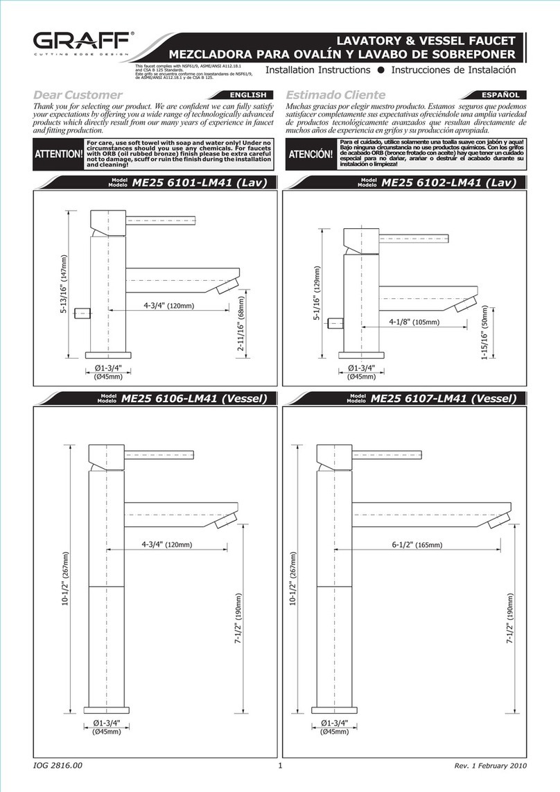
This manual suits for next models

4

Other Graff Bathroom Fixture manuals

Graff LMB40-BS User manual

Graff

Graff LMB40-BS User manual

Graff AMETIS G-8765 User manual

Graff

Graff AMETIS G-8765 User manual

Graff E-6910-C16B-PC Operator's manual

Graff

Graff E-6910-C16B-PC Operator's manual

Graff E-9960 5591000 Operator's manual

Graff

Graff E-9960 5591000 Operator's manual

Graff ONDA E-6335-LM61W Series Operator's manual

Graff

Graff ONDA E-6335-LM61W Series Operator's manual

Graff 2335000 Operator's manual

Graff

Graff 2335000 Operator's manual

Graff Cameo E-11943-LM69 User manual

Graff

Graff Cameo E-11943-LM69 User manual

Graff Camden E-8509 Operator's manual

Graff

Graff Camden E-8509 Operator's manual

Graff E-11401-C19L Operator's manual

Graff

Graff E-11401-C19L Operator's manual

Graff MUS92 User manual

Graff

Graff MUS92 User manual

Graff GX-6170-LM3F User manual

Graff

Graff GX-6170-LM3F User manual

Graff SENTO-6355-T User manual

Graff

Graff SENTO-6355-T User manual

Graff Cameo E-18037-RK Operator's manual

Graff

Graff Cameo E-18037-RK Operator's manual

Graff E-6190-LM41R User manual

Graff

Graff E-6190-LM41R User manual

Graff ONDA E-7080-LM61N-T Operator's manual

Graff

Graff ONDA E-7080-LM61N-T Operator's manual

Graff E-6111N-C17B Operator's manual

Graff

Graff E-6111N-C17B Operator's manual

Graff E-11520 L1 Series Operator's manual

Graff

Graff E-11520 L1 Series Operator's manual

Graff IMMERSION 2310-C9 User manual

Graff

Graff IMMERSION 2310-C9 User manual

Graff TEP92 User manual

Graff

Graff TEP92 User manual

Graff Immersion 2357-LM31N-T User manual

Graff

Graff Immersion 2357-LM31N-T User manual

Graff G-8220 User manual

Graff

Graff G-8220 User manual

Graff C14U-WS Series User manual

Graff

Graff C14U-WS Series User manual

Graff SOLAR Operator's manual

Graff

Graff SOLAR Operator's manual

Graff 8618 User manual

Graff

Graff 8618 User manual

Popular Bathroom Fixture manuals by other brands

Franke F5ST2020 Installation and operating instructions

Franke

Franke F5ST2020 Installation and operating instructions

Mirolin STRADA Series Installation and owner's manual

Mirolin

Mirolin STRADA Series Installation and owner's manual

DURAVIT 2nd floor 0790400071 Mounting instructions

DURAVIT

DURAVIT 2nd floor 0790400071 Mounting instructions

Teuco SEASIDE T07 user manual

Teuco

Teuco SEASIDE T07 user manual

Fleurco ADT4836-3 installation manual

Fleurco

Fleurco ADT4836-3 installation manual

Hans Grohe Sportive 32004000 manual

Hans Grohe

Hans Grohe Sportive 32004000 manual

Tylo ix210 installation instructions

Tylo

Tylo ix210 installation instructions

Grohe Eurostyle Cosmopolitan 33 982 manual

Grohe

Grohe Eurostyle Cosmopolitan 33 982 manual

Watermark Lily LLD4 quick start guide

Watermark

Watermark Lily LLD4 quick start guide

Relax 0206-F2 Assembly instructions

Relax

Relax 0206-F2 Assembly instructions

Kohler K-3082 installation guide

Kohler

Kohler K-3082 installation guide

Interline 57100905 instruction manual

Interline

Interline 57100905 instruction manual

Korpinen 21273117-00 instruction manual

Korpinen

Korpinen 21273117-00 instruction manual

Kohler K-7514 installation guide

Kohler

Kohler K-7514 installation guide

Helvex H-201 installation guide

Helvex

Helvex H-201 installation guide

Exclusive Heritage CL-10172D-WMTP installation guide

Exclusive Heritage

Exclusive Heritage CL-10172D-WMTP installation guide

Hewi 477.93.010 Mounting instructions

Hewi

Hewi 477.93.010 Mounting instructions

Kohler K-1010 Installation and care guide

Kohler

Kohler K-1010 Installation and care guide

manuals.online logo
manuals.online logoBrands
  • About & Mission
  • Contact us
  • Privacy Policy
  • Terms and Conditions

Copyright 2025 Manuals.Online. All Rights Reserved.