manuals.online logo
Brands
  1. Home
  2. •
  3. Brands
  4. •
  5. Grange
  6. •
  7. Lawn And Garden Equipment
  8. •
  9. Grange FLOWER WALK PERGOLA User manual

Grange FLOWER WALK PERGOLA User manual

ADDING AN EXTENSION TO YOUR FLOWER WALK
PERGOLA
EXTENSION HARDWARE PACK
CURVED SECTION 6
FOOT 2
METAL RODS 7
WASHERS 14
PLASTIC CUP 7
CAPS 7
STEP 22
Glue and screw the curved beams as steps 2-4.
STEP 23
Fix the feet to the curved beam assembly as steps 4-6.
ALLOW THE GLUE TO SET OVERNIGHT.
STEP 24
Mark the positions for the anchors and fix in place.
STEP 25
Remove the Plastic Caps (
c
) from the ends of
the
assembled Flower Walk that is to be extended
NB. replacement cups and caps are supplied.
STEP 26
Remove the Plastic Cup, if fitted, and undo the
M10 nut. Discard the old cups and caps.
STEP 27
Screw one of the metal rods from the extension
pack into one of the positions just released.
Ensure the metal washer is fitted.
STEP 28
Screw the remaining six metal rods into the
existing structure.
STEP 29
Fit washers between the metal rods
and the curved beam assembly.
STEP 30
Fit the curved beam assembly using
the replacement cups and washers.
Fixin placeusing either the M10 bolt
orM10 nut previously removed.
STEP 31
Now tighten the metal rods into the existing structure.
Oncethey are all tight, tighten the M10 bolt or M10 nut.
STEP 32
Fix the feet to the anchors.
STEP 33
Finally, fit the caps to the plastic cups.
THE EXTENSION AS PART OF THE INITIAL BUILD
Any number of extensions may be added to the basic pack. The extension pack provides all of the parts required to build a longer
Flower Walk by following the main instruction procedure.
TIP
An attractive addition to the Flower Walk is to fit border troughs along the sides.
1
2
3
a
b
c
1
2
3
abc
7cm
To ensure longevity of your structure it is recommended that it is treated with a wood preservative on a yearly basis.
AFTERCARE
FLWCCLB - 228cm [H] x 240cm [W] x 258cm [D]
FLOWER WALK PERGOLA
[PACK B]
Self-Assembly required Home Delivery available Pre-Painted available
www.grangefen.co.uk
All products and related emblems featured are
trademarks of Grange Fencing Ltd.
©2015 Grange Fencing Ltd All rights reserved.
In line with the Company’s policy of
continuous product development, the right
is reserved to change and improve product
design without prior notice.
CODE: FLWCCLB
PLAN
240cm
80cm - 90cm
112cm
228cm 217.5cm
258cm
BEFORE YOU START
•Please ensure that you check all the component parts for quantity and quality before you commence building the
product. Report any missing parts immediately. The manufacturer will not accept any responsibility for damaged items
once any part of the product has been fitted or altered in any way.
•Timber is a natural material and will react to varying levels of moisture content - ie. will swell or shrink. All of the Timber
components are pressure treated green. However, should extra protection be required, they should be treated using a
wood preservative treatment, following the maintenance instructions.
HEALTH AND SAFETY
Do not overstretch when working from the step ladder.
In order to reduce the risk of suffocation please keep all plastic bags and small parts away from children.
•When you are ready to start, make sure you have the right tools to hand, plenty of space and a
clean, dry area for assembly. It is advisable for two people to carry out the work.
PREPARATION
Make sure the area where the Flower Walk is to be positioned is clear and ready for building the structure.
Thank you for choosing this garden structure from Grange.
PLEASE READ THE ASSEMBLY INSTRUCTIONS THOROUGHLY BEFORE ATTEMPTING TO ERECT THE STRUCTURE
ESTIMATED BUILD TIME - 6 HOURS (OVER TWO DAYS)
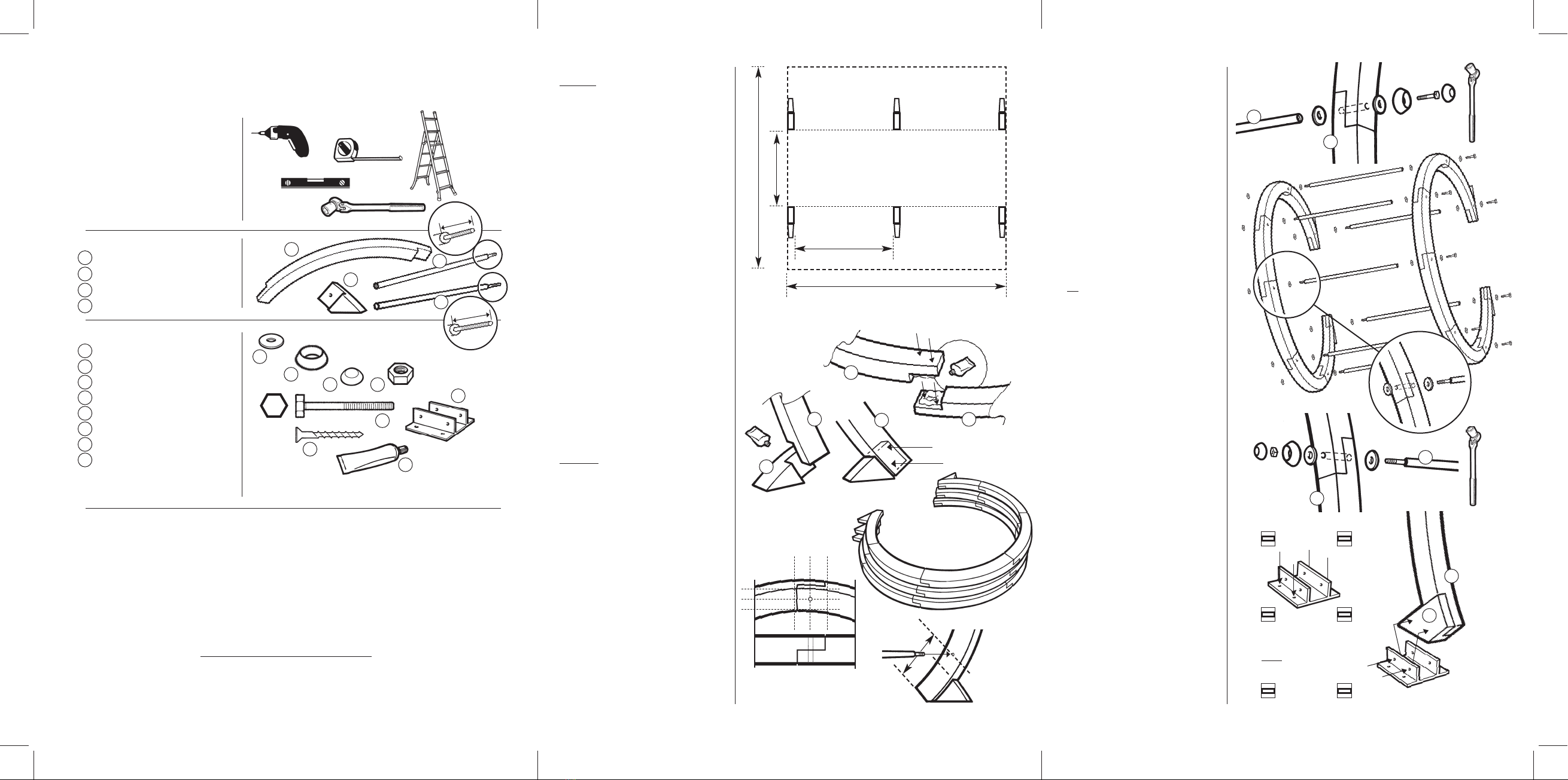
TOOLS REQUIRED (Not Supplied)
POWER DRILL
(+ crosshead screwdiver bit)
SPIRIT LEVEL
TAPE MEASURE
STEPLADDER
1.7cm BI-HEX SOCKET + HANDLE
PARTS LIST
CURVED SECTION 18
FOOT 6
METAL RODS (7cm) 7
METAL RODS (6cm) 7
HARDWARE PACK
WASHER 42
PLASTIC CUP 14
CAP 14
10mm NUT 7
M10 x 70 HEXBOLT 7
M4 x 40 SCREW 66
WOOD GLUE 1
CONCRETE ANCHOR 6
ASSEMBLY INSTRUCTIONS
PART ONE
To ensure a sound structure, it is recommended
that the sections which form the Circle are
assembled and glued then allowed to set for 24
hours before continuing.
STEP 1
Make sure you have a clean, flat dry area, big
enough to assemble a circle.
(see Pergola ‘footprint’ - right - for dimensions).
Remember - the circle, once assembled will need
to be left undisturbed for 24 hours.
STEP 2
ASSEMBLING THE CIRCLE
Take two of the curved sections and apply glue to
one of the joint faces. Fix the joint together and
screw in place using two screws (f).
STEP 3
Continue from one end of the assembly with the
next curved section repeating step 2.
STEP 4
Fix three more curved beams in the same manner.
STEP 5
Take one of the Feet (2)and fix to one end of the
circleassembly (as fig.2).
STEP 6
Repeat the procedure for the other end of the
circle assembly.
STEP 7
Repeat steps 2-6 for the two remaining circles.
STEP 8
Lay the circles on top of one another (as fig.3).
Leave for 24 hours for the glue to set fully.
ASSEMBLY INSTRUCTIONS
PART TWO
STEP 9
Mark the hole positions for where the metal rods
will be fixed.
The position should be in the centre of the joints
except for the two joints for the feet. These
should be marked in the centre of the beam
15cm from the end.
STEP 10
Now, using the 1.2cm drill bit make a hole
through all three circles at the marked points.
This is to ensure correct alignment of the
structure.
STEP 11
Place the assembled circles as close as possible to
their final positions
(seefootprint at top of page).
STEP 12
Take one of the Metal Rods (3)with the 7cm
thread and fix it to one of the end curved
beam assemblies (as shown in fig.6).
Tighten bolt (e)using a 1.7cm socket.
STEP 13
Fit metal rods to the remaining six holes for
the circle assembly as in step 12.
STEP 14
Fit Washers (a)to the threaded ends of the
metal rods.
STEP 15
Fit the next circle assembly over the
protruding threads.
STEP 16
Fit a Washer (a)and a metal rod (4)with the
6cm thread to each of the threads protruding
through the circle assembly. Tighten the rods
in place as tight as possible.
TIP
Keep working around the rods in turn to
tighten them.
STEP 17
Fit washers to the metal rod threads and then
fit the remaining circle assembly.
STEP 18
Fitwashers to the protruding threads before
fitting a Plastic Cup (b)and M10 nut (d).
Tighten the nuts using a socket as before as
tightly as possible.
STEP 19
Using the dimensions of the completed
structure, mark the positions for the anchors
(h).
STEP 20
Fix the anchors into position then lift the
structure into place in the anchors.
Ensurethe structure is aligned correctly.
Using screws (f)fix the structure into the
anchors.
STEP 21
Once the structure is fixed in its final position
and securely fastened down, fit the caps (c)
to the plastic cups.
NB. Once the caps are fitted they cannot
easily be removed without incurring
damage.
FOR DETAIL OF ADDING AN EXTENSION
TO THE EXISTING FLOWER WALK SEE
OVERLEAF.
1
a
b
c
d
e
f
g
h
2
3
4
1
2
3
4
a
b
cd
e
f
g
h
258cm
STEP 10
STEPS 2-7
15cm
Fix lower metal rods 15cm from
end of curved beams and 5cm
above foot joints
PERGOLA “FOOTPRINT’
121cm
239cm
82cm
1
1
1
1
3
f
f
f
f
g
(fig.2) (fig.3)
(fig.6)
=
=
=
=
1
3
a
e
c
b
STEP 12-13
STEP 14-17
STEP 18
1
4
a
d
f
f
c
d
STEP 20
Position and fix
all anchors (h)
before inserting
structure into them
1
2
STEP 8
7cm
6cm

This manual suits for next models

1

Other Grange Lawn And Garden Equipment manuals

Grange URBAN SCREEN PLANTER User manual

Grange

Grange URBAN SCREEN PLANTER User manual

Grange ERP User manual

Grange

Grange ERP User manual

Grange 220701A014OMBZ08C1 User manual

Grange

Grange 220701A014OMBZ08C1 User manual

Grange ESLP User manual

Grange

Grange ESLP User manual

Grange ELITE SQUARE PLANTER - LARGE User manual

Grange

Grange ELITE SQUARE PLANTER - LARGE User manual

Grange 220907A001OSBZ04C1 User manual

Grange

Grange 220907A001OSBZ04C1 User manual

Grange Apollo User manual

Grange

Grange Apollo User manual

Grange ELITE SQUARE PLANTER MEDIUM User manual

Grange

Grange ELITE SQUARE PLANTER MEDIUM User manual

Grange TRADITIONAL PERGOLA User manual

Grange

Grange TRADITIONAL PERGOLA User manual

Grange PKITCAG User manual

Grange

Grange PKITCAG User manual

Grange Bow Top Arch User manual

Grange

Grange Bow Top Arch User manual

Grange PKITCRAG User manual

Grange

Grange PKITCRAG User manual

Grange CONTEMPORARY User manual

Grange

Grange CONTEMPORARY User manual

Grange RUSTIC ROSE PERGOLA User manual

Grange

Grange RUSTIC ROSE PERGOLA User manual

Grange 220901A008OZBZ06C1 User manual

Grange

Grange 220901A008OZBZ06C1 User manual

Grange STEPLA User manual

Grange

Grange STEPLA User manual

Grange ROPE WALK PERGOLA User manual

Grange

Grange ROPE WALK PERGOLA User manual

Grange Bow Top Arch User manual

Grange

Grange Bow Top Arch User manual

Grange FLOWER WALK PERGOLA User manual

Grange

Grange FLOWER WALK PERGOLA User manual

Grange 220600A007OMBZ01C1 User manual

Grange

Grange 220600A007OMBZ01C1 User manual

Grange ELITEARCH User manual

Grange

Grange ELITEARCH User manual

Grange VALENCIA ARCH User manual

Grange

Grange VALENCIA ARCH User manual

Grange 222308B002MMBZ01C1 User manual

Grange

Grange 222308B002MMBZ01C1 User manual

Grange 221500A001AABZ06C1 User manual

Grange

Grange 221500A001AABZ06C1 User manual

Popular Lawn And Garden Equipment manuals by other brands

Sunforce SOLAR user manual

Sunforce

Sunforce SOLAR user manual

GARDEN OF EDEN 55627 user manual

GARDEN OF EDEN

GARDEN OF EDEN 55627 user manual

Goizper Group MATABI POLMINOR instruction manual

Goizper Group

Goizper Group MATABI POLMINOR instruction manual

Rain Bird 11000 Series Operation & maintenance manual

Rain Bird

Rain Bird 11000 Series Operation & maintenance manual

Cub Cadet BB 230 brochure

Cub Cadet

Cub Cadet BB 230 brochure

EXTOL PREMIUM 8891590 Translation of the original user manual

EXTOL PREMIUM

EXTOL PREMIUM 8891590 Translation of the original user manual

Snapper 690179 installation instructions

Snapper

Snapper 690179 installation instructions

Exmark SAR481KA30 Operator's manual

Exmark

Exmark SAR481KA30 Operator's manual

Yazoo/Kees Z12 Operator's manual

Yazoo/Kees

Yazoo/Kees Z12 Operator's manual

Makita EM408MP Original instruction manual

Makita

Makita EM408MP Original instruction manual

Exmark Quest Bagger Setup instructions

Exmark

Exmark Quest Bagger Setup instructions

Manitou Systems AS960 Operator's manual

Manitou Systems

Manitou Systems AS960 Operator's manual

Vertex 1/3 HP Maintenance instructions

Vertex

Vertex 1/3 HP Maintenance instructions

GHE AeroFlo 80 manual

GHE

GHE AeroFlo 80 manual

Land Pride Post Hole Diggers HD25 Operator's manual

Land Pride

Land Pride Post Hole Diggers HD25 Operator's manual

Yazoo/Kees Z9 Commercial Collection System Z9A Operator's & parts manual

Yazoo/Kees

Yazoo/Kees Z9 Commercial Collection System Z9A Operator's & parts manual

Premier designs WindGarden 26829 Assembly instructions

Premier designs

Premier designs WindGarden 26829 Assembly instructions

Snapper 1691351 installation instructions

Snapper

Snapper 1691351 installation instructions

manuals.online logo
manuals.online logoBrands
  • About & Mission
  • Contact us
  • Privacy Policy
  • Terms and Conditions

Copyright 2025 Manuals.Online. All Rights Reserved.