manuals.online logo
Brands
  1. Home
  2. •
  3. Brands
  4. •
  5. Grange
  6. •
  7. Lawn And Garden Equipment
  8. •
  9. Grange FLOWER WALK PERGOLA User manual

Grange FLOWER WALK PERGOLA User manual

FLOWER WALK
PERGOLA
ASSEMBLY INSTRUCTIONS
GRANGE FENCING LIMITED
Halesfield 21, Telford TF7 4PA
Tel: 01952 588088 Fax: 01952 581522
Email: [email protected]
Web: www.grangefen.co.uk
2.275m
2.175m
1.12m
820mm
2.58m
TOP VIEW FRONT VIEW
2.39m
TIP
An attractive addition to the Flower Walk is to fit border troughs along the sides.
Grange offer the following products that may be used to construct the troughs:
•ROUNDED GARDEN SLEEPERS •ELITE HEAVY DUTY GRAVEL BOARDS
•ELITE DECKING BOARDS •TIMBER BOLLARDS
STEP 12
Take one of the Metal Rods (3)with the
70mm thread and fix it to one of the end
curved beam assemblies
(as shown in fig.6).
Tighten bolt (e)using a 17mm socket.
STEP 13
Fit metal rods to the remaining six holes
for the circle assembly as in step 12.
STEP 14
Fit Washers (a) to the threaded ends of the
metal rods.
STEP 15
Fit the next circle assembly over the
protruding 70mm threads.
STEP 16
Fit a Washer (a) and a metal rod (4) with
the 60mm thread to each of the threads
protruding through the circle assembly.
Tighten the rods in place as tight as
possible.
TIP
Keep working around the rods in turn to
tighten them.
STEP 17
Fit washers to the metal rod threads and
then fit the remaining circle assembly.
STEP 18
Fit washers to the protruding threads
before fitting a Plastic Cup (b) and M10
nut (d).
Tighten the nuts using a socket as before
as tightly as possible.
STEP 19
Using the dimensions of the completed
structure, mark the positions for the
anchors (hor j).
STEP 20
Fix the anchors into position then lift the
structure into place in the anchors.
Ensure the structure is aligned correctly.
Using screws (f) fix the structure into the
anchors.
STEP 21
Once the structure is fixed in its final
position and securely fastened down, fit
the caps (c) to the plastic cups.
NB. Once the caps are fitted they
cannot easily be removed without
incurring damage.
(fig.6)
1
3
a
e
c
b
STEP 12-13
STEP 14-17
STEP 18
1
4
a
b
f
f
c
d
STEP 20
Position and fix
all anchors (hor j)
before inserting
structure into them
or
1
2
h
j
THE GRANGE FLOWER WALK PERGOLA IS MADE OF PRESSURE
TREATED AND FSC CERTIFIED TIMBER AND AS SUCH IS GUARANTEED
AGAINST ROT FOR A MINIMUM OF 15 YEARS. HOWEVER, IT MUST BE
REMEMBERED THAT AS A NATURAL PRODUCT, TIMBER IS SUBJECT TO
MOVEMENT AND WEATHERING AS IT SEASONS. IT IS NOT
UNCOMMON FOR SMALL SPLITS TO OCCUR WHEN DRYING AND
WARPING WHEN TIMBER IS ALLOWED TO DRY TOO RAPIDLY. THESE
WILL NORMALLY GO BACK WHEN HUMIDITY RISES. IT IS NATURE AT
WORK AND NOT CONSIDERED A FAULT.
ITS COLOUR WILL ALSO CHANGE WITH TIME. A RETREATMENT, AS
REQUIRED WITH A PROPRIETARY WOOD TREATMENT IS
RECOMMENDED.
CARE OF YOUR PERGOLA
BEFORE YOU START
•Please ensure that you check all the component parts for quantity and quality before you
commence building the product. Report any missing parts immediately. The manufacturer will
not accept any responsibility for damaged items once any part of the product has been fitted or
altered in any way.
•Timber is a natural material and will react to varying levels of moisture content - ie. will swell or
shrink. All of the Timber components are pressure treated green. However, should extra
protection be required, they should be treated using a wood preservative treatment, following the
maintenance instructions.
HEALTH AND SAFETY
Do not overstretch when working from the step ladder.
In order to reduce the risk of suffocation please keep all plastic bags and small parts away from children.
•When you are ready to start, make sure you have the right tools to hand, plenty of space and a
clean, dry area for assembly. It is advisable for two people to carry out the work.
PREPARATION
Make sure the area where the Flower Walk is to be positioned is clear and ready for building the structure.
Thank you for choosing this garden structure from Grange Fencing Ltd.
PLEASE READ THE ASSEMBLY INSTRUCTIONS THOROUGHLY BEFORE ATTEMPTING TO
ERECT THE STRUCTURE
ESTIMATED BUILD TIME - 6 HOURS (OVER TWO DAYS)
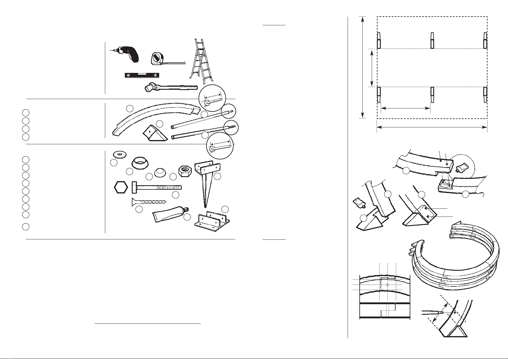
TOOLS REQUIRED (Not Supplied)
POWER DRILL
+ crosshead screwdriver bit
+ 12mm wood drill bit
SPIRIT LEVEL
TAPE MEASURE
STEPLADDER
17mm BI-HEX SOCKET + HANDLE
PARTS LIST
CURVED SECTION 18
FOOT 6
METAL RODS (70mm) 7
METAL RODS (60mm) 7
HARDWARE PACK
WASHER 42
PLASTIC CUP 14
CAP 14
10mm NUT 7
M10 x 70 HEX BOLT 7
M4 x 40 SCREW 66
WOOD GLUE 1
SOIL ANCHOR 6
(optional)
CONCRETE ANCHOR 6
(optional)
ASSEMBLY INSTRUCTIONS
PARTONE
To ensure a sound structure, it is
recommended that the sections which
form the Circle are assembled and glued
then allowed to set for 24 hours before
continuing.
STEP 1
Make sure you have a clean, flat dry
area, big enough to assemble a circle.
(see Pergola ‘footprint’ - right - for dimensions).
Remember - the circle, once
assembled will need to be left
undisturbed for 24 hours.
STEP 2
ASSEMBLING THE CIRCLE
Take two of the curved sections and
apply glue to one of the joint faces. Fix
the joint together and screw in place
using two screws (f).
STEP 3
Continue from one end of the assembly
with the next curved section repeating
step 2.
STEP 4
Fix three more curved beams in the
same manner.
STEP 5
Take one of the Feet (2) and fix to one
end of the circle assembly (as fig.2).
STEP 6
Repeat the procedure for the other end
of the circle assembly.
STEP 7
Repeat steps 2-6 for the two remaining
circles.
STEP 8
Lay the circles on top of one another
(as fig.3). Leave for 24 hours for the
glue to set fully.
PART TWO
STEP 9
Mark the hole positions for where the
metal rods will be fixed.
The position should be in the centre of
the joints except for the two joints for
the feet. These should be marked in the
centre of the beam 150mm from the end.
STEP 10
Now, using the 12mm drill bit make a
hole through all three circles at the
marked points. This is to ensure
correct alignment of the structure.
IT IS IMPORTANT TO ENSURE THAT THE
DRILL IS VERTICAL SO THAT THE HOLES
ARE DRILLED THROUGH SQUARELY
.
STEP 11
Place the assembled circles as close as
possible to their final positions
(see footprint at top of page).
1
a
b
c
d
e
f
g
h
j
2
3
4
1
2
3
4
a
b
cd
e
f
g
h
j
2.58m
STEP 10
STEPS 2-7
150mm
Fix lower metal rods 150mm
from end of curved beams
and 50mm above foot joints
PERGOLA “FOOTPRINT’
1.21m
2.39m
820mm
1
1
1
1
3
f
f
f
f
g
(fig.2) (fig.3)
=
=
=
=
STEP 8
70mm
60mm

Other Grange Lawn And Garden Equipment manuals

Grange VALENCIA ARCH User manual

Grange

Grange VALENCIA ARCH User manual

Grange Bow Top Arch User manual

Grange

Grange Bow Top Arch User manual

Grange ELITE GRANVILLE ARCH User manual

Grange

Grange ELITE GRANVILLE ARCH User manual

Grange 222308B002MMBZ01C1 User manual

Grange

Grange 222308B002MMBZ01C1 User manual

Grange ELITE BOW TOP ARCH User manual

Grange

Grange ELITE BOW TOP ARCH User manual

Grange ROPE WALK PERGOLA User manual

Grange

Grange ROPE WALK PERGOLA User manual

Grange ELITE SQUARE PLANTER MEDIUM User manual

Grange

Grange ELITE SQUARE PLANTER MEDIUM User manual

Grange PKITCAG User manual

Grange

Grange PKITCAG User manual

Grange ESLP User manual

Grange

Grange ESLP User manual

Grange RUSTIC ROSE PERGOLA User manual

Grange

Grange RUSTIC ROSE PERGOLA User manual

Grange PKITCRAG User manual

Grange

Grange PKITCRAG User manual

Grange Bow Top Arch User manual

Grange

Grange Bow Top Arch User manual

Grange Apollo User manual

Grange

Grange Apollo User manual

Grange ELITEPORTE User manual

Grange

Grange ELITEPORTE User manual

Grange FLOWER WALK PERGOLA User manual

Grange

Grange FLOWER WALK PERGOLA User manual

Grange ELITEARCH User manual

Grange

Grange ELITEARCH User manual

Grange 220907A001OSBZ04C1 User manual

Grange

Grange 220907A001OSBZ04C1 User manual

Grange CONTARB User manual

Grange

Grange CONTARB User manual

Grange URBAN SCREEN PLANTER User manual

Grange

Grange URBAN SCREEN PLANTER User manual

Grange 221500A001AABZ06C1 User manual

Grange

Grange 221500A001AABZ06C1 User manual

Grange ELITE SQUARE PLANTER - LARGE User manual

Grange

Grange ELITE SQUARE PLANTER - LARGE User manual

Grange 220901A008OZBZ06C1 User manual

Grange

Grange 220901A008OZBZ06C1 User manual

Grange 221401A001OSBZ04C1 User manual

Grange

Grange 221401A001OSBZ04C1 User manual

Grange TRADITIONAL PERGOLA User manual

Grange

Grange TRADITIONAL PERGOLA User manual

Popular Lawn And Garden Equipment manuals by other brands

PrimAster PMGBS 7225 operating instructions

PrimAster

PrimAster PMGBS 7225 operating instructions

Makita EM4251CA Parts Breakdown

Makita

Makita EM4251CA Parts Breakdown

FMF Powerline Installation

FMF

FMF Powerline Installation

Echo 06999999 Operator's manual

Echo

Echo 06999999 Operator's manual

Holman 40101 Instruction guide

Holman

Holman 40101 Instruction guide

Outdoor living today 12x8 Cabana Assembly manual

Outdoor living today

Outdoor living today 12x8 Cabana Assembly manual

Sherpa STS40-S owner's manual

Sherpa

Sherpa STS40-S owner's manual

AL-KO Comfort 38-5 instruction manual

AL-KO

AL-KO Comfort 38-5 instruction manual

Worx WG801 manual

Worx

Worx WG801 manual

Wolf Garten A 320 E manual

Wolf Garten

Wolf Garten A 320 E manual

Craftsman 358.792410 Operator's manual

Craftsman

Craftsman 358.792410 Operator's manual

aquanique GP 3200 operating instructions

aquanique

aquanique GP 3200 operating instructions

Gardigo 78480 instruction manual

Gardigo

Gardigo 78480 instruction manual

GARDEN SECRETS GS-502 User instructions

GARDEN SECRETS

GARDEN SECRETS GS-502 User instructions

Retractable Awnings Hamburg installation instructions

Retractable Awnings

Retractable Awnings Hamburg installation instructions

Gardeners 8610207 quick start guide

Gardeners

Gardeners 8610207 quick start guide

Stihl SPA 65 instruction manual

Stihl

Stihl SPA 65 instruction manual

Worx Landroid Original instructions

Worx

Worx Landroid Original instructions

manuals.online logo
manuals.online logoBrands
  • About & Mission
  • Contact us
  • Privacy Policy
  • Terms and Conditions

Copyright 2025 Manuals.Online. All Rights Reserved.