OK
0º
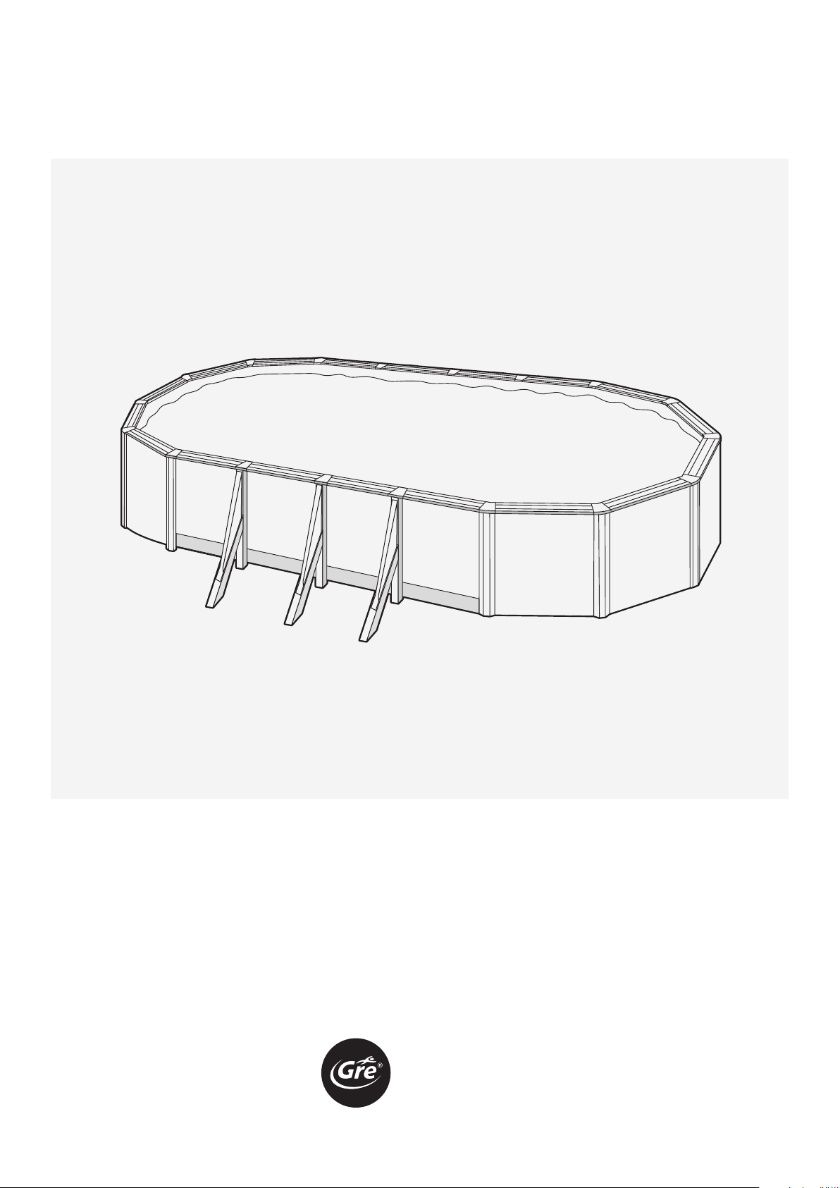
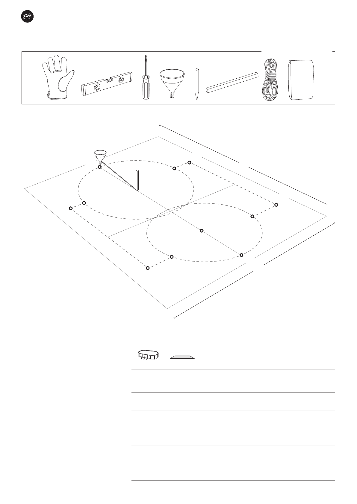
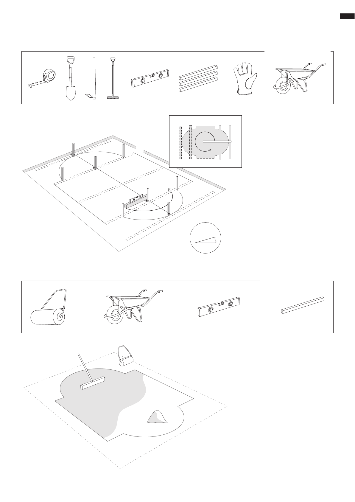
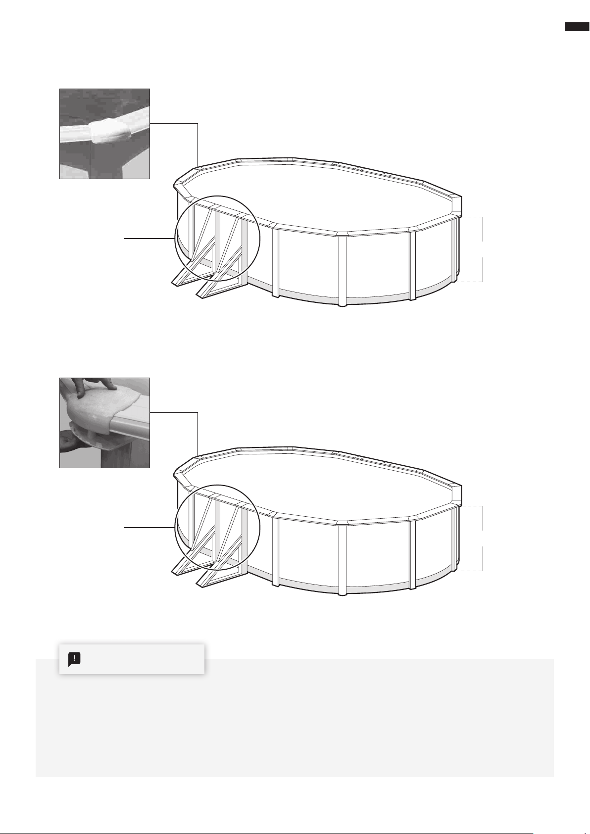
assembly instructions
Safety
precautions.
Carefully read, understand, and follow all infor-
mation in this user manual before installing and
using the swimming pool.
These warnings, instructions, and safety guide-
lines address some common risks of water rec-
reation, but they cannot cover all risks and dan-
gers in all cases.
Always use caution, common sense, and good
judgment when enjoying any water activity. Re-
tain this information for future use.
Non swimmers safety
Continuous, active, and vigilant supervision of
weak swimmers and non-swimmers by a com-
petent adult is required at all times (remember-
ing that children under five are at the highest
risk of drowning).
→ Designate a competent adult to supervise the
pool each time it is being used.
→ Weak swimmers or non-swimmers should wear
personal protection equipment when using the
pool.
→ When the pool is not in use, or unsupervised,
remove all toys from the swimming pool and
its surrounding to avoid attracting children to
the pool.
Safety devices
→ It is recommended to install a barrier (and se-
cure all doors and windows, where applicable)
to prevent unauthorized access to the swim-
ming pool.
→ Barriers, pool covers, pool alarms, or similar
safety devices are helpful aids, but they are not
substitutes for continuous and competent adult
supervision.
Safety equipment
→ It is recommended to keep rescue equipment
(e.g. a ring buoy) by the pool.
→ Keep a working phone and a list of emergency
phone numbers near the pool.
Safe use of the pool
→ Encourage all users especially children to learn
how to swim
→ Learn Basic Life Support (Cardiopulmonary
Resuscitation - CPR) and refresh this knowl-
edge regularly.
This can make a life-saving difference in the
event of an emergency:
→ Instruct all pool users, including children, what
to do in case of an emergency
→ Never dive into any shallow body of water. This
can lead to serious injury or death.
→ Do not use the swimming pool when using
alcohol or medication that may impair your
ability to safely use the pool.
→ When pool covers are used, remove them
completely from the water surface before en-
tering the pool.
→ Protect pool occupants from water related ill-
nesses by keeping the pool water treated and
practicing good hygiene. Consult the water
treatment guidelines in the user’s manual.
→ Store chemicals (e.g. water treatment, clean-
ing or disinfection products) out of the reach
of children.
→ Signage is to be displayed in a prominent po-
sition within 2 m of the pool.
→ Removable ladders shall be placed on a hori-
zontal surface.
WARNING
Every electrical appliance fed in 220 V, has to
be located at least at 3,50 m from the edge
of the pool.
The equipment should be connected to a
voltage, with earth connection, protected
by a residual current device (RCD) having a
rated residual operating current not exceed-
ing 30mA.
Read the instructions carefully and keep
for future reference.
IF YOU HAVE ANY PROBLEM, CONTACT
US!
www.grepool.com/en/after-sales
→ If you have decided to install a salt chlorinator,
it must be fitted with a grounding connection
and sacrificial anode to prevent the appear-
ance of rust on the metal parts.. Otherwise,
should any of the metal components (ladder,
pool wall, profiles, etc.) become rusty they will
not be covered by the warranty. For more in-
formation on these parts, please contact your
dealer.
4