manuals.online logo
Brands
  1. Home
  2. •
  3. Brands
  4. •
  5. Growatt
  6. •
  7. Measuring Instrument
  8. •
  9. Growatt Smart Meter-US User manual

Growatt Smart Meter-US User manual

Electricity Meter
&
Installation Guide V1.0
Growatt New Energy
Growatt USA,Inc
9227 Reseda Blvd,#435 Northridge,CA 91324,USA.
+818 800-9177
www.growatt-america.com
T
E usaservice@ginverter.com
W
SM-US-200
Contents
1 Introduction
2 Meter Installation
2.1 Installation Guidelines
2.2 Installing and Connecting the Meter
3 Panel introduction
4 Meter Technical
Specifications
5 Dimensions
3.1 Meter Status Leds
3.2 Button description
5.1 Meter Dimensions(±0.5mm)
5.2 Current Transformers Dimensions
(±0.5mm)
APPENDIX
Accessories list
Specification Revision 1.0
IMPORTANT SAFETY INSTRUCTIONS
SAVE THESE INSTRUCTIONS
This manual contains important instructions for Model SM-US-200 that shall be followed
during installation and maintenance of the inverter.
Risk of electrical shock
Risque d'électrocution
Wait for 5minutes before engaging in the indicated action
Attendez 5 minutes avant de vous engager dans l'action indiquée
Observe the operating instructions
Respectez les instructions de service
IMPORTANT SAFETY INSTRUCTIONS
1 Introduction
1
2
In a single inverter system, the meter is connected directly to the inverter. If your inverter
has a built-in revenue grade meter (RGM; the inverter is referred to a revenue grade
inverter), you can connect an external meter on the same bus as the RGM.
Fig 1.1
Meter Installation 2
2.1 Installation Guidelines
While Installing the meter, the National Electrical Code, ANSI/NFPA 70 and Canadian
Electrical Code C22.1. shall be used.
The meter is connected to the inverter using RS485.
AC wire specifications: 1.3 to 2.0 mm diameter / 22-18 AWG stranded wire, 600 V, type
THHN, MTW, or THWN.
RS485 wiring specifications:
lCable type: Min. 3-wire shielded twisted pair (a 4-wire cable may be used)
Wire cross-section area: 0.32- 0.81 mm²/ 24-18 AWG (a CAT5 cable may be used).
lThe meter is considered “permanently connected equipment” and requires a
disconnect means (circuit breaker, switch, or disconnect) and overcurrent protection
(fuse or circuit breaker).
lThe meter draws 10-30mA, therefore the rating of any switches, disconnects, fuses,
and/ or circuit breakers is determined by the wire gauge, the mains voltage, and the
current interrupting rating required.
lThe switch, disconnect, or circuit breaker must be located near the meter and be
easily operated .
lUse circuit breakers or fuses rated for 20A or less.
lUse grouped circuit breakers when monitoring more than one line.
lThe circuit breakers or fuses must protect the mains terminals labeled L1and L2. In
the rare cases where neutral has overcurrent protection, the overcurrent protection
device must interrupt both neutral and the ungrounded conductors simultaneously.
lThe circuit protection / disconnect system must meet all national and local electrical
codes.
Note
If using a cable longer than 10 m/33 ft in areas where there is a risk of
induced voltage surges by lightning, it is recommended to use external
surge protection devices. If grounded metal conduit is used for routing the
communication wires, there is no need for a lightning protection device.
2.2 Installing and Connecting the Meter
2.2.1 To mount the meter
1.The meter should be mounted in a Power Distribution Box.
2.Mount the meter on a 35mm DIN rail.
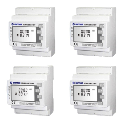
34
Fig 2.1
2.2.2 To install the CTs
1.Turn off AC power before clamping on current transformers.
2.Install the CTs around the conductor to be measured. Split-core CTs can be opened for
3installation around a conductor. A nylon cable tie may be secured around the CT to
prevent accidental opening.
3.Install the CT with the arrow pointing to the load.
The current transformer is packed together with the meter.
2.2.3 To wire the meter
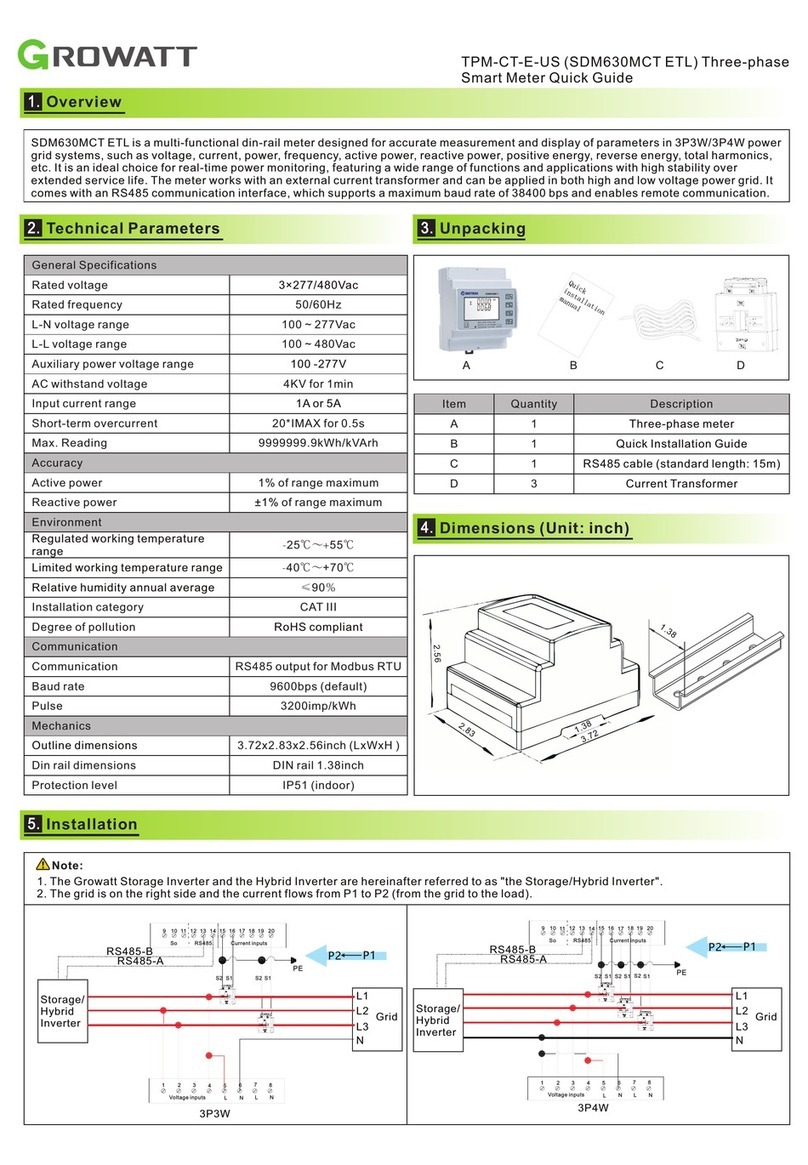
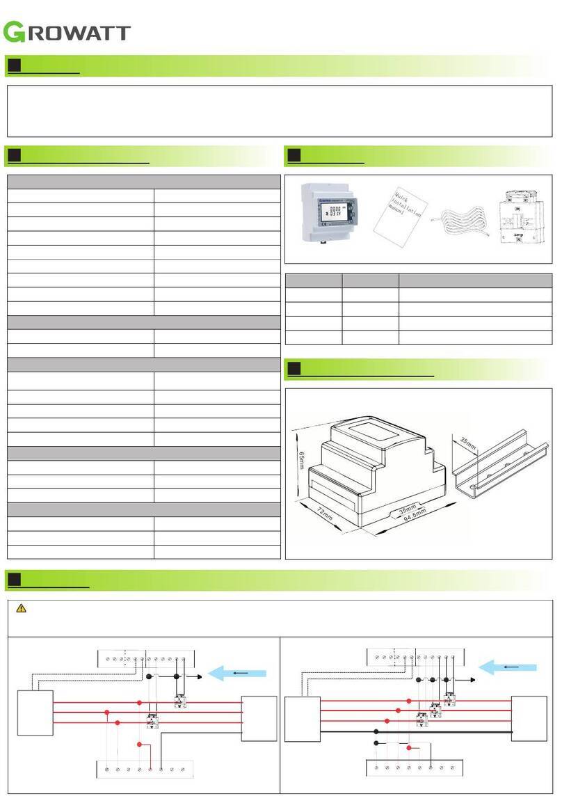
If you are connecting the meter to the inverter, Refer to the connection diagram below
Note
lClamp the CT connected to L1 CT around the wire connected to ØL1.
lClamp the CT connected to L2 CT around the wire connected to ØL2.
Fig 2.2
1.Verify that power is OFF before making connections.
2.Insert a grounding cable through the appropriate conduit and the knockout that was
opened and connect it from Pin 5 of the 5-pin terminal block to the grounding terminal
3.Connect the AC side wires (meter input) using the 5-pin terminal block:
ØInsert the wires through the appropriate conduit and the knockout that was opened.
ØLoosen the appropriate screws on the 5-pin terminal block.
ØConnect each AC wire to the appropriate screw terminal (pins 1, 2). Verify that the
lines match the symbols printed on the meter front label.
ØConnect ground to pin 5 and neutral to pin 3.
ØTighten the screws making sure the wires are fully inserted and cannot be pulled out
easily.
ØInsert the 5-pin terminal block into the socket on the meter making sure it is fully
seated in the meter.
4.Connect the CT wires to the 4-pin terminal block(block1):
ØInsert the wires through the appropriate conduit and the knockout that was opened.
ØConnect the blue and brown wires according to the dots printed on the label: blue to
pins 1/3, brown to pins 2/4.
ØInsert the 4-pin terminal block into the socket on the meter making sure it is fully
seated in the meter.
5.Connect the RS485 twisted pair cable to the 4-pin terminal block o(block2):
ØInsert the wires through the appropriate conduit and the knockout that was opened.
ØConnect the wires to the A+ and B- terminals, and connect the shield to the G
terminal.
ØInsert the 4-pin terminal block into the socket on the meter making sure it is fully
seated in the meter.
6.Return the terminal block end-stops to the sides of the meter.
Note
If the meter is used for two-phase two-wire system(no neutral) ,please
connect L2 and N line at the 5-pin terminal block:
1
2
3
4
5
Block1 Block2
1
2
3
4
Red(L1 ) -t o pin 1
Black(L2 ) -t op i n 2
White(N)- t o pin 3
Green/Ye l l o w(GND) - t o p in 5
Wi r e s f ro m A C :
L1
L2
AC :C T wires:
bl u e t o p in 1,3
br o w n t o pi n 2,4
To t h e l o ad
L1 C T L 2 CT
RS485 wi r e s
1
2
3
4
A+
B-
6
5
3 Panel introduction Meter Technical Specifications 4
3.1 Meter Status Leds
The three status LEDs on the front of the meter can help indicate correct measurements
and operation.
At normal startup - when power is first applied, all the LEDs light up sequentially for 1
sec.
3.3.1 Power Status LED
LED
LED Color
Function
Indication
Troubleshooting
RUN
Green
Flashing ON/OFF
(for 1sec)
Work normally
/
Red
ON for>3sec
Intermal error
Contact Support
Yellow
Flashing ON/OFF
(for 1sec)
No comunication
Check that the
communication wires are
connected correctly.
3.3.2 Phase Status LED
LED
LED Color
Function
Indication
L1/L2
Green
ON for>3sec
No Currnet
Flashing ON/OFF
(for 1sec)
Positive power
Red
Flashing ON/OFF
(for 1sec)
Negative power
Check for reversed
CTs, swapped CT
wires, or CTs not
matched with the
lines.
Flashing with green LED
High voltage>130V
Check the line
voltages and the meter
rating.
Flashing with yellow LED
Low voltage<70V
Yellow
Flashing ON/OFF
(for 1sec)
Break fault<30V
ON for>3sec
Frequency is below
45Hz or above 70Hz
Check for the presence
of high noise.
3.2 Button description
When the software version of the meter needs to bo updated,Refer to the following
steps:
Øcommunicate with the meter by RS 485.
ØOpen the programming software, load the new software to update.
ØPress the “reset” button for 3sec,the meter will restart.
ØWait for the program to be completed.
Meter Electrical Service
Units
SM-US-200
Rated Voltage-Line to N
120
V
Rated Voltage-Line to Line
208/240
V
Extended Voltage Range
88%~110%
AC Frequency
60
Hz
Grids Supported
L1/L2/N/PE
Power Consumption
1.2
Communication
Meter Communication Interfaces
RS 485
Response Time
≦1
S
Meter Accuracy
Rated RMS current
100
200
A
1%-100% of CT Current
±0.5
±1
%
Current Transformers
Number of Supplied Current Transformers
2
Dimensions
I.D:15 O.D:35
70.5×54.5×39
(H×W×D)
mm
Standard Compliance
Safety
Ul1741
Installation Specifications
Dimensions(H×W×D)
54.1×87.8×52
mm
Weight
0.2
kg
Operating Temperature Range
-30~55
℃
Relative Humidity (noncondensing)
5 - 90
%
Mounting Type
DIN-Rail,35mm
78
5 Dimensions
5.1 Meter Dimensions(±0.5mm)
5.2 Current Transformers Dimensions(±0.5mm)
46.5
54.8
2 3 .0
2 3 .0
5 1 .9
70.5
3 9 .0
Fig 5.1
Fig 5.2
APPENDIX
Accessories list
Item
Quantity
Current Transformer
2
Plug component
3
Specification Revision 1.0
Contents subject to change with notice to contract customers.

This manual suits for next models

1

Other Growatt Measuring Instrument manuals

Growatt ShineLink-X User manual

Growatt

Growatt ShineLink-X User manual

Growatt TPM-CT-E-US User manual

Growatt

Growatt TPM-CT-E-US User manual

Growatt Lucas User manual

Growatt

Growatt Lucas User manual

Growatt Shine3G Instruction sheet

Growatt

Growatt Shine3G Instruction sheet

Growatt ShineWiFi Instruction sheet

Growatt

Growatt ShineWiFi Instruction sheet

Growatt ShineMaster User manual

Growatt

Growatt ShineMaster User manual

Growatt ShineLink-X Operating and maintenance instructions

Growatt

Growatt ShineLink-X Operating and maintenance instructions

Growatt ShineLimit User manual

Growatt

Growatt ShineLimit User manual

Growatt SPH Series User manual

Growatt

Growatt SPH Series User manual

Growatt Shine GPRS-F User manual

Growatt

Growatt Shine GPRS-F User manual

Growatt ShineVision User manual

Growatt

Growatt ShineVision User manual

Growatt ShineWiFi-X Instruction sheet

Growatt

Growatt ShineWiFi-X Instruction sheet

Growatt ShineWiFi-X User manual

Growatt

Growatt ShineWiFi-X User manual

Growatt MOD 3-15KTL3-X User manual

Growatt

Growatt MOD 3-15KTL3-X User manual

Growatt ShineWiFi-X User manual

Growatt

Growatt ShineWiFi-X User manual

Growatt ShineWiFi-S Instruction sheet

Growatt

Growatt ShineWiFi-S Instruction sheet

Growatt ShineWiFi-X User manual

Growatt

Growatt ShineWiFi-X User manual

Growatt TPM-CT-E-EU User manual

Growatt

Growatt TPM-CT-E-EU User manual

Growatt TPM-E SDM630-Modbus V3 User manual

Growatt

Growatt TPM-E SDM630-Modbus V3 User manual

Growatt MIN TL-X Manual

Growatt

Growatt MIN TL-X Manual

Growatt TPM-CT-C-EU User manual

Growatt

Growatt TPM-CT-C-EU User manual

Popular Measuring Instrument manuals by other brands

Campbell TDR100 instruction manual

Campbell

Campbell TDR100 instruction manual

Grodan WCM-control quick guide

Grodan

Grodan WCM-control quick guide

ABB SensyMaster FMT230 Commissioning Instruction

ABB

ABB SensyMaster FMT230 Commissioning Instruction

Hach DR 6000 user manual

Hach

Hach DR 6000 user manual

Renishaw RMP600 installation guide

Renishaw

Renishaw RMP600 installation guide

Spotsee SpotBot Cellular product manual

Spotsee

Spotsee SpotBot Cellular product manual

Thermo Scientific MIRAN 205B Series instruction manual

Thermo Scientific

Thermo Scientific MIRAN 205B Series instruction manual

Sensaphone 800 user manual

Sensaphone

Sensaphone 800 user manual

Xylem WTW OxiTop-IDS Multi 3630 IDS operating manual

Xylem

Xylem WTW OxiTop-IDS Multi 3630 IDS operating manual

Chauvin Arnoux CA 10141E user manual

Chauvin Arnoux

Chauvin Arnoux CA 10141E user manual

LumaSense IN 300/5 Operation manual

LumaSense

LumaSense IN 300/5 Operation manual

Gigahertz Solutions HF35C manual

Gigahertz Solutions

Gigahertz Solutions HF35C manual

AlazarTech ATS9626 user manual

AlazarTech

AlazarTech ATS9626 user manual

Hanna Instruments HI 991401 user manual

Hanna Instruments

Hanna Instruments HI 991401 user manual

DH Instruments AMH-100 Operation and maintenance manual

DH Instruments

DH Instruments AMH-100 Operation and maintenance manual

Teledyne Lecroy Frontline Sodera LE quick start guide

Teledyne Lecroy

Teledyne Lecroy Frontline Sodera LE quick start guide

RS PRO RS 1400 Series operating manual

RS PRO

RS PRO RS 1400 Series operating manual

Bixion III user guide

Bixion

Bixion III user guide

manuals.online logo
manuals.online logoBrands
  • About & Mission
  • Contact us
  • Privacy Policy
  • Terms and Conditions

Copyright 2025 Manuals.Online. All Rights Reserved.