manuals.online logo
Brands
  1. Home
  2. •
  3. Brands
  4. •
  5. Growatt
  6. •
  7. Measuring Instrument
  8. •
  9. Growatt TPM-E SDM630-Modbus V3 User manual

Growatt TPM-E SDM630-Modbus V3 User manual

1.1.
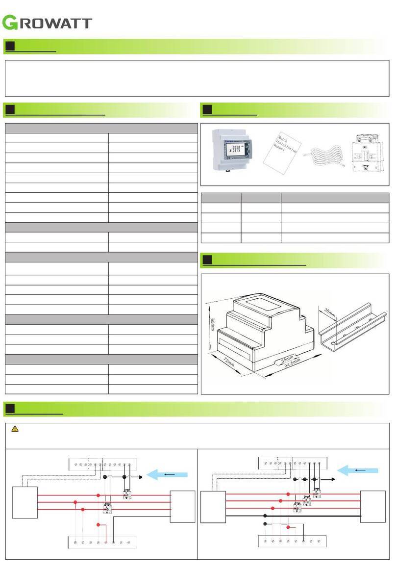
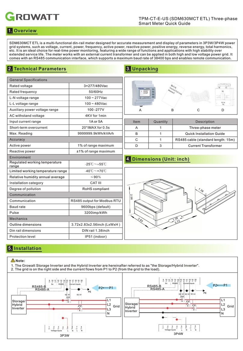
SDM630-Modbus V3 is a multi-function rail meter, it can accurately measure and display various power parameters in 1P2W/3P3W/3P4W:
voltage, current, power, frequency, active power, reactive power, forward power, reverse power, total harmonics, etc. The meter is suitable
for real-time power monitoring system, with multi-function, multi-purpose, high stability and long life characteristics. The meter is connected
with an external current transformer and is suitable for various high and low voltage power grids. The meter has RS485 communication
interface, supports the highest communication rate of 38400bps, can realize remote communication.
Overview
2. 3.
Unpacking
TPM-E(SDM630-Modbus V3) Three-phase
Smart Meter Quick Guide(MOD 3-10KTL3-XH)
General Specifications
Rated voltage
3×230/400Vac
Rated frequency
50/60Hz
L-N voltage range
100 ~ 289Vac
L-L voltage range
173 ~ 480Vac
Auxiliary power voltage range
85 ~ 275Vac or 120 ~ 380Vdc
AC withstand voltage
4KV for 1min
Input current range
<40mA
Short-term overcurrent
20*IMAX for 0.5s
Max. Reading
9999999.9kWh/kVArh
Accuracy
Active power
0.5% of range maximum
Reactive power
1% of range maximum
Environment
Rated temperature
-25℃~+55℃
Limit temperature
-40℃~+70℃
Relative humidity(average annual)
≤90%
Installation category
CAT III
Degree of pollution
Conform to RoHS
Communication
Communication
RS485 output for Modbus RTU
Baud rate
9600bps(default)
Pulse
3200imp/kWh
Mechanics
Mounting dimensions
94.5x72x65mm(LxWxH )
Din rail dimensions
DIN rail 35mm
Protection level
Ip51 (indoor)
Item
Quantity
Description
A
1
Three-phase meter(TPM-E)
B
1
User Manual
C
1
RS485 cable (standard length 15m)
Overview
Technical Parameters
A B C
4.
Dimension(Unit:mm)
5.
Installation
a.The network cable is described as follows:
b.Cut the crystal head, find out PIN1 and PIN5, and connect the
communication terminals according to the picture.
c.Connect the communication terminals as shown.
d.Connect the communication terminals to the 30-pin
communication terminals of the inverter.
e.The standard RS485 cable length is 15m.If need longer RS485
cable,please use an ethernet coupler to extend and make sure
RS485 cable less than 100m(the recommended length is less than
25m).
f.MOD XH system application block diagram wiring is as follows.
6.
Button Definition And Display
There are four touch buttons on the panel, from top to bottom are “ESC(←)V/A”, “↑(Alt)MD/PH/HZ”, “↓(Shift)P”, “ENTER(→)E”. There are
two types of key operation: long press(Press for more than two seconds) and short press(Pressing time is less than one second).
NO.
Button
Features
Viewable content(short press)
1
Short press:
display voltage and current, ←
Long press: ESC
Phase voltage, Line voltage, Phase current, Neutral
current, Voltage harmonics, Current harmonics
2
Short press: display power factor and
frequency, ↑
Long press: Alt
Phase(Total) frequency, Total power factor, Phase(Total)
maximum current demand
3
Short press: display power, ↓
Long press: Shift
Phase(Total) active power, Phase(Total) reactive power,
Phase(Total) apparent power
4
Short press:
display electric energy, →
Long press: Enter
Total active electric energy, Total reactive electric energy,
Forward active electric energy, Reverse active electric
energy, Forward reactive electric energy, Reverse
reactive electric energy
ESC
Cut off
PIN 6
PIN 5
RS485B-
PIN 1 White Orange
RS485A+
PIN 5 White Blue
Meter Pin NO. Description Meter Connection
1/2/3/4
5/6/7/8
A
B
L1/L2/L3/N-in
L1/L2/L3/
N-out
RS485A
RS485B
Grid L1/L2/L3/N
AC connector & Load L1/L2/L3/N
COM Port Pin 5 RS485A3
COM Port Pin 6 RS485B3
Breaker Meter
Note:Please connect according to the above diagram, the meter power line and communication line need to be in one-to-one
correspondence.
Shenzhen Growatt New Energy CO.,LTD
+86 0755 2747 1942 +86 0755 2747 1942
www.ginverter.comwww.ginverter.com
T
E
W
service@ginverter.comservice@ginverter.com
Download
Manual
Growatt New Energy
GR-UM-209-A-01GR-UM-209-A-01
7.
Trouble Shooting
Fault phenomenon
Reason analysis
Solution
Big deviation between electric
energy measurement and
actual value.
1. Wiring error, voltage and current corresponding
phase sequence is wrong.
2. If the output line of the current transformers is
reversed.
3. The transformer ratio is not set, the meter
displays the secondary data.
1. Refer to the wiring diagram to check the wiring.
2. If the transformer ratio setting is wrong, please
set the voltage ratio and current ratio correctly.
3. If the issue still exists,please contact your local
supplier.
RS485 communication error
(Inverter error 401)
1. RS485 cable is open circuit,short circuit or
resersely.
2. The address, baud rate and data parity of the
meter do not match the MOD-XH.
1. If there is a problem with the communication
cable, please replace the communication cable.
2. Set the correct address, baud rate, and data bit
check digit of the meter by the button.
3. If the issue still exists,please contact your local
supplier.
Setting examples of current ratio
Measure
display
Long Press
Long Press
Long Press
Short Press
Short Press
Short Press
Default
password
is 1000
Press
Then Long prsee to confirm the settings
and to adjust the value
Enter into
the setting
interface
When CT1 is set
to 150,the primary
cutten is 150A
Power on
to enter the current ration setting interface
X 5
Add
ESC
8.
Service and contact
4-13/F,Building A,Sino-German(Europe) Industrial Park,
Hangcheng Ave, Bao'an District, Shenzhen, China
Note:This meter and MOD-XH default communication address is 02, the baud rate is 9600, the current ratio is 150A/40mA, if the meter
and MOD-XH communication is not on, you can confirm the communication address and baud rate is accurate. Long press to enter
setting menu(default password is 1000), then use and to find the page to be set. If the page flashes, means it can be set
through and , otherwise you should press to enter. When you set OK, long press to confirm and then
press to exit setting.

Other Growatt Measuring Instrument manuals

Growatt ShineWiFi-S Instruction sheet

Growatt

Growatt ShineWiFi-S Instruction sheet

Growatt MOD 3-15KTL3-X User manual

Growatt

Growatt MOD 3-15KTL3-X User manual

Growatt Shine GPRS-F User manual

Growatt

Growatt Shine GPRS-F User manual

Growatt Shine3G Instruction sheet

Growatt

Growatt Shine3G Instruction sheet

Growatt MIN TL-X Manual

Growatt

Growatt MIN TL-X Manual

Growatt Smart Meter-US User manual

Growatt

Growatt Smart Meter-US User manual

Growatt ShineMaster User manual

Growatt

Growatt ShineMaster User manual

Growatt TPM-CT-E-US User manual

Growatt

Growatt TPM-CT-E-US User manual

Growatt ShineVision User manual

Growatt

Growatt ShineVision User manual

Growatt ShineWiFi-X User manual

Growatt

Growatt ShineWiFi-X User manual

Growatt TPM-CT-C-EU User manual

Growatt

Growatt TPM-CT-C-EU User manual

Growatt ShineWiFi-X Instruction sheet

Growatt

Growatt ShineWiFi-X Instruction sheet

Growatt ShineLimit User manual

Growatt

Growatt ShineLimit User manual

Growatt ShineWiFi-X User manual

Growatt

Growatt ShineWiFi-X User manual

Growatt ShineLink-X Operating and maintenance instructions

Growatt

Growatt ShineLink-X Operating and maintenance instructions

Growatt SPH Series User manual

Growatt

Growatt SPH Series User manual

Growatt ShineWiFi-X User manual

Growatt

Growatt ShineWiFi-X User manual

Growatt TPM-CT-E-EU User manual

Growatt

Growatt TPM-CT-E-EU User manual

Growatt ShineWiFi Instruction sheet

Growatt

Growatt ShineWiFi Instruction sheet

Growatt ShineLink-X User manual

Growatt

Growatt ShineLink-X User manual

Growatt Lucas User manual

Growatt

Growatt Lucas User manual

Popular Measuring Instrument manuals by other brands

PHYWE Cobra4 operating instructions

PHYWE

PHYWE Cobra4 operating instructions

PlantCare Plant Thirsty Light user manual

PlantCare

PlantCare Plant Thirsty Light user manual

Waltron Aqualert 6051 instruction manual

Waltron

Waltron Aqualert 6051 instruction manual

Facom 714 instruction manual

Facom

Facom 714 instruction manual

SIGLENT SSA3000X-R user manual

SIGLENT

SIGLENT SSA3000X-R user manual

Olympus USPM-RU-W Series Operation manual

Olympus

Olympus USPM-RU-W Series Operation manual

eltherm ELK-MI-AY825 operating manual

eltherm

eltherm ELK-MI-AY825 operating manual

Kane 456 manual

Kane

Kane 456 manual

Anaheim Scientific H400 instruction manual

Anaheim Scientific

Anaheim Scientific H400 instruction manual

YARL DGTAL user guide

YARL

YARL DGTAL user guide

Svantek SV258 PRO user guide

Svantek

Svantek SV258 PRO user guide

Crowcon Xgard ESU C01987 Installation, operation and maintenance instructions

Crowcon

Crowcon Xgard ESU C01987 Installation, operation and maintenance instructions

Chauvin Arnoux C.A 8336 user manual

Chauvin Arnoux

Chauvin Arnoux C.A 8336 user manual

PCB Piezotronics 353B77 Installation and operating manual

PCB Piezotronics

PCB Piezotronics 353B77 Installation and operating manual

Phoenix Contact TESTFOX CC operating manual

Phoenix Contact

Phoenix Contact TESTFOX CC operating manual

METREL EurotestCOMBO MI 3125 instruction manual

METREL

METREL EurotestCOMBO MI 3125 instruction manual

GF ER 52 instruction manual

GF

GF ER 52 instruction manual

Welch Allyn GSI 38 Service manual

Welch Allyn

Welch Allyn GSI 38 Service manual

manuals.online logo
manuals.online logoBrands
  • About & Mission
  • Contact us
  • Privacy Policy
  • Terms and Conditions

Copyright 2025 Manuals.Online. All Rights Reserved.