2Automated Roll-Up Sides Revision date: 12.16.20
BEFORE YOU BEGIN
Thank you for purchasing this automated roll-up side kit for high tunnels. When properly installed and maintained, the components in this kit will provide years of
reliable service. If you have any questions during the assembly, contact Customer Service at 1.800.245.9881 for assistance.
Important Information
ASSEMBLY PROCEDURE
Steps outlining assembly are as follows:
1. Verify that all parts are included in the shipment. Notify customer service
for questions or concerns.
2. Read these instructions and all additional documentation included
before you begin.
3. Gather tools.
SAFETY PRECAUTIONS
• Wear eye protection.
• Wear gloves when handling metal pipes.
• Wear head protection and steel-toed footwear.
• Use a portable GFCI (Ground Fault Circuit Interrupter) when working with
power tools and cords. Use battery-powered tools when possible.
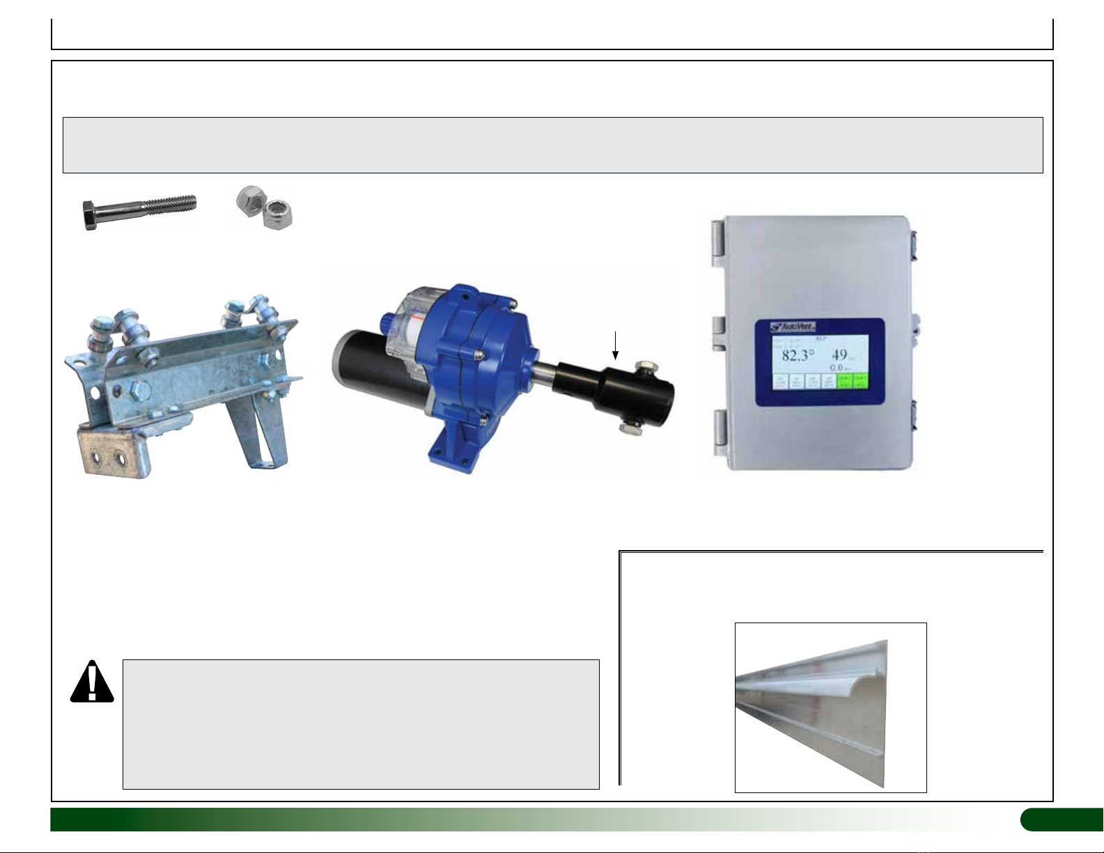
UNPACK AND IDENTIFY PARTS
The following steps help ensure you have all necessary parts before you
begin.
1. Unpack shipment contents and place where you can easily inventory
parts. Refer to the Bill of Materials/Spec Sheets.
2. Verify all parts listed on Bill of Materials/Spec Sheets are present. If
anything is missing or you have questions, consult Pictorial Parts Guide
and all diagrams for clarification, then contact Customer Service if
needed.
NOTE: At this time, you do not need to open the plastic bags containing
smaller parts such as fasteners or washers (if equipped).
REQUIRED TOOLS
The following list identifies the main tools needed to install the automated roll-
up kit components. Additional tools may be needed.
• Tape measure and marker.
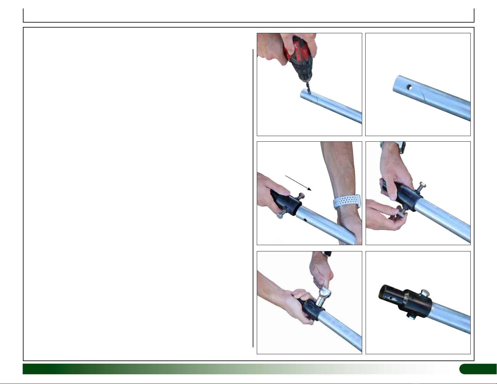
• Clutched drill and driver to drive Tek screws (if equipped) and drill holes.
(Cordless with extra batteries works best.) Do not use an impact driver
to install Tek screws.
• Drill bit index with 7/16" bit to install guide post and guide post stop bolts.
• Metric socket and ratchet set and a metric wrench set that includes: 10,
13, 16, & 17mm sizes.
• Hex (Allen) wrench or bit set that includes a 4mm size.
• Hack saw or power saw equipped with a metal-cutting blade to cut pipe.
• Ladder to connect guide post at the top. ATTENTION: ALL ELECTRICAL CONNECTIONS TO BE COMPLETED
IN ACCORDANCE WITH LOCAL AND REGIONAL CODES BY A
PROFESSIONAL, LICENSED AND QUALIFIED CONTRACTOR.
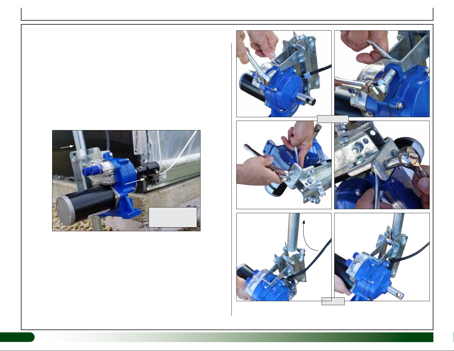
WARNING — ENTANGLEMENT DANGER! KEEP CLEAR OF ROTATING
SHAFT! DO NOT WEAR LOOSE CLOTHING, JEWELRY, OR LONG
HAIR WHEN NEAR THE DRIVE MOTOR, ROLL-UP CONDUIT, MOTOR
BRACKET, OR ROLL-UP PANEL.
MOTOR OPERATION IS AUTOMATIC AND CAN BEGIN WITHOUT
NOTICE AT ANYTIME! KEEP CHILDREN AWAY AT ALL TIMES!