English (GB)
5
English (GB) Installation and operating instructions
Original installation and operating instructions.
CONTENTS
Page
1. Symbols used in this document
2. General information
These installation and operating instructions are a supplement to
installation and operating instructions for the corresponding
standard pumps TP, TPD, NK, NKG and NB, NBG. For
instructions not mentioned specifically here, please see
installation and operating instructions for the standard pump.
3. General description
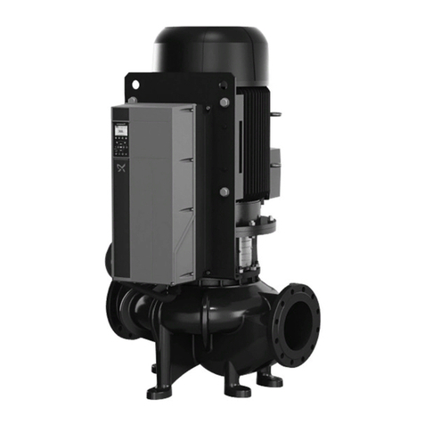
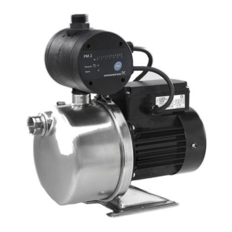
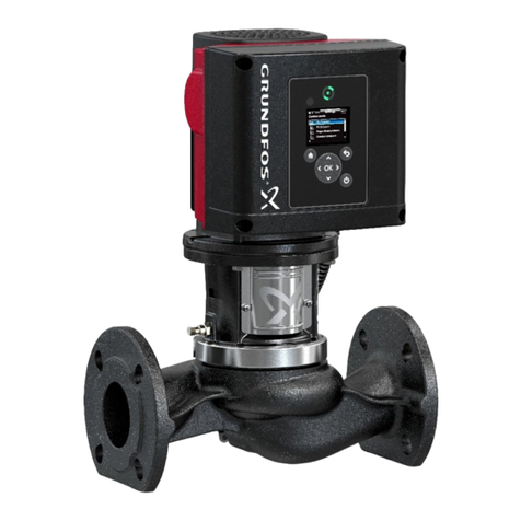
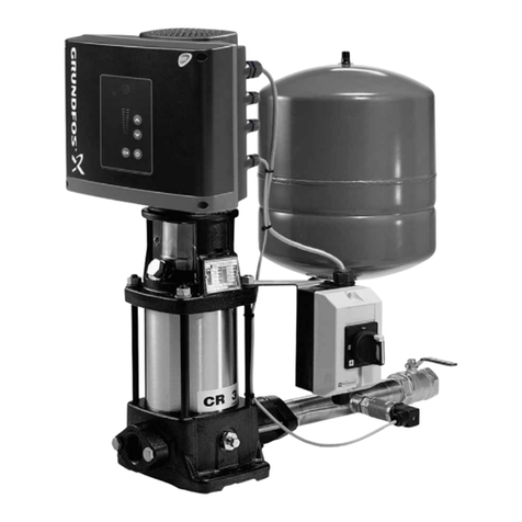
Grundfos E-pumps have standard motors with integrated
frequency converter. The pumps are for single-phase or three-
phase mains connection.
The pumps have a built-in PI controller and can be set up for an
external sensor enabling control of the following parameters:
•pressure
• differential pressure
•temperature
• differential temperature
•flow.
From factory, the pumps have been set to control mode
uncontrolled. The PI controller can be activated by means of
R100.
The pumps are typically used as circulator pumps in large heating
or cooling water systems with variable demands.
3.1 Settings
The desired setpoint, can be set in three different ways:
• directly on the pump control panel
• via an input for external setpoint signal
• by means of the Grundfos wireless remote control R100.
All other settings are made by means of the R100.
Important parameters such as actual value of control parameter,
power consumption, etc. can be read via the R100.
3.2 Twin-head pumps
Twin-head pumps do not require any external controller.
1. Symbols used in this document 5
2. General information 5
3. General description 5
3.1 Settings 5
3.2 Twin-head pumps 5
4. Mechanical installation 6
4.1 Motor cooling 6
4.2 Outdoor installation 6
5. Electrical connection 6
5.1 Cable requirements 6
5.2 Electrical connection - single-phase pumps 6
5.3 Electrical connection - three-phase pumps up to 7.5
kW 8
5.4 Electrical connection - three-phase pumps, 11-22 kW 10
5.5 Signal cables 13
5.6 Bus connection cable 13
5.7 Communication cable for TPED pumps 13
6. Modes 14
6.1 Overview of modes 14
6.2 Operating mode 14
6.3 Control mode 15
6.4 Factory setting 15
7. Setting by means of control panel 15
7.1 Setpoint setting 16
7.2 Setting to max. curve duty 16
7.3 Setting to min. curve duty 16
7.4 Start/stop of pump 16
8. Setting by means of R100 16
8.1 Menu OPERATION 18
8.2 Menu STATUS 19
8.3 Menu INSTALLATION 20
9. Setting by means of PC Tool E-products 23
10. Priority of settings 23
11. External forced-control signals 24
11.1 Start/stop input 24
11.2 Digital input 24
12. External setpoint signal 24
13. Bus signal 25
14. Other bus standards 25
15. Indicator lights and signal relay 25
16. Insulation resistance 26
17. Emergency operation (only 11-22 kW) 27
18. Maintenance and service 28
18.1 Cleaning of the motor 28
18.2 Relubrication of motor bearings 28
18.3 Replacement of motor bearings 28
18.4 Replacement of varistor (only 11-22 kW) 28
18.5 Service parts and service kits 28
19. Technical data - single-phase pumps 28
19.1 Supply voltage 28
19.2 Overload protection 28
19.3 Leakage current 28
19.4 Inputs/outputs 28
20. Technical data - three-phase pumps up to 7.5 kW 29
20.1 Supply voltage 29
20.2 Overload protection 29
20.3 Leakage current 29
20.4 Inputs/output 29
21. Technical data - three-phase pumps, 11-22 kW 29
21.1 Supply voltage 29
21.2 Overload protection 29
21.3 Leakage current 29
21.4 Inputs/output 30
22. Other technical data 30
23. Disposal 32
Warning
Prior to installation, read these installation and
operating instructions. Installation and operation
must comply with local regulations and accepted
codes of good practice.
Warning
If these safety instructions are not observed, it may
result in personal injury!
Warning
The surface of the product may be so hot that it may
cause burns or personal injury.
If these safety instructions are not observed, it may
result in malfunction or damage to the equipment.
Notes or instructions that make the job easier and
ensure safe operation.
