GTD LM1000 N BSWP User manual

GTD-LM1000 N BSWP
User Manual

GTD all rights reserved. Information, specifications, diagrams, images, and instructions herein are subject to change without
notice. GTD logo and identifying product names and numbers herein are trademarks of GTD. Copyright protection claimed
includes all forms and matters of copyrightable materials and information now allowed by statutory or judicial law or
hereinafter granted. Product names used in this document may be trademarks or registered trademarks of their respective
companies and are hereby acknowledged. All non-GTD brands and product names are trademarks or registered trademarks
of their respective companies.
GTD and all affiliated companies hereby disclaim any and all liabilities for property, equipment, building, and electrical
damages, injuries to any persons, and direct or indirect economic loss associated with the use or reliance of any information
contained within this document, and/or as a result of the improper, unsafe, insufficient and negligent assembly, installation,
rigging, and operation of this product.
Guangzhou GTD Culture & Technology Group Co.,Ltd. | 27 Fu Yuan Yi Road, Guangzhou 510805, P.R.China
P/N:1502010374A

Contents
1. Safety instructions.......................................................................................................................................................1
2. Product introductions.................................................................................................................................................3
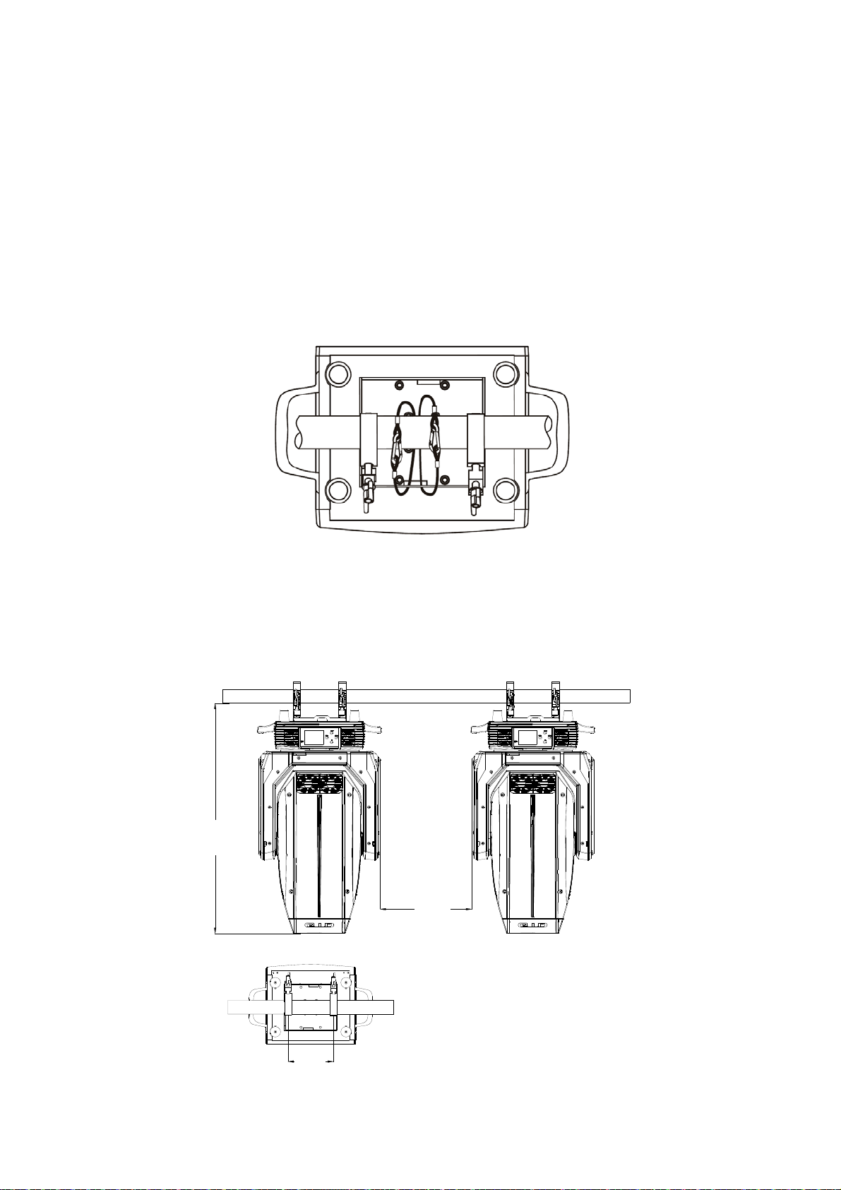
2.1 Dimensions.............................................................................................................................................................. 3
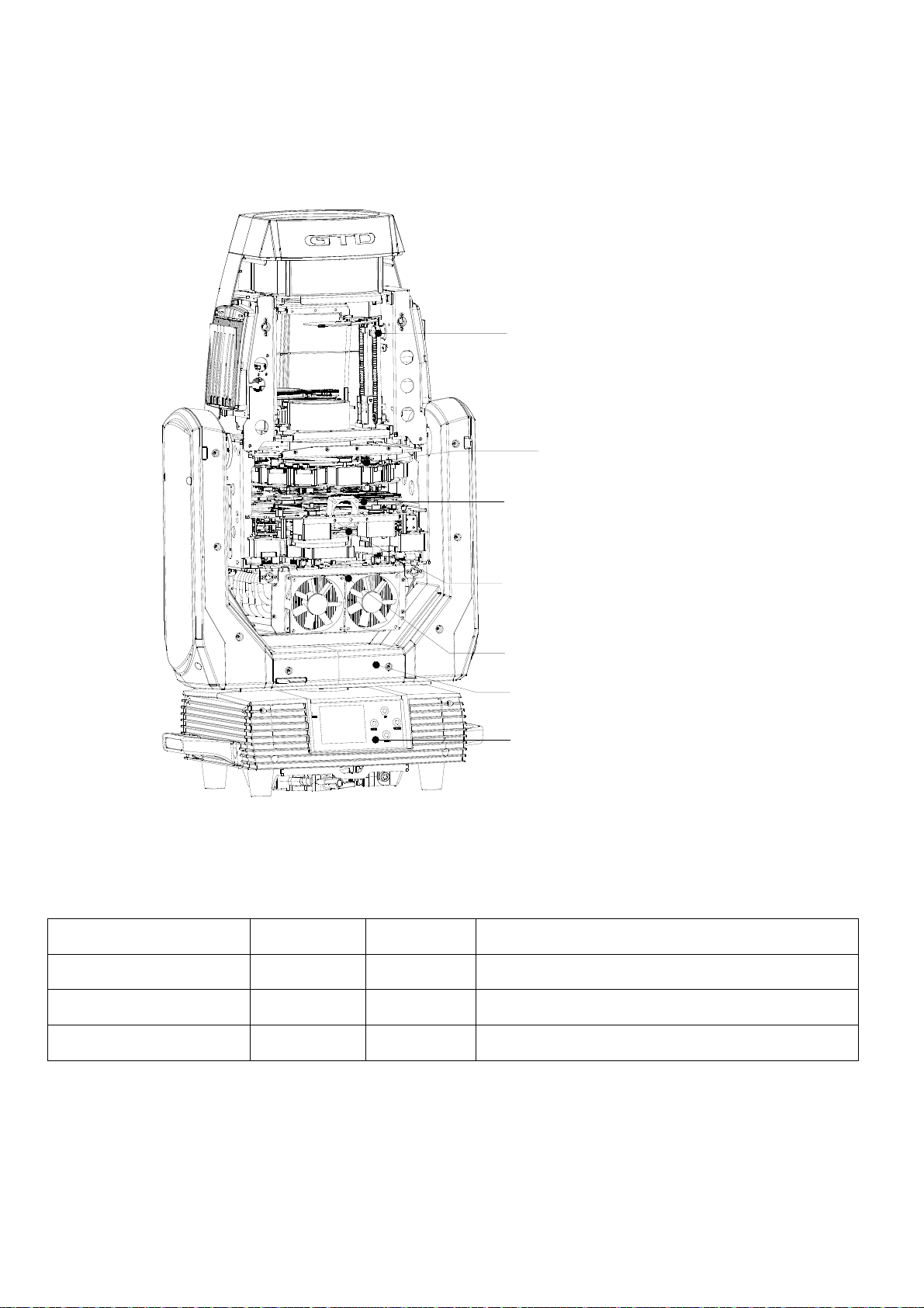
2.2 Fixture overview ..................................................................................................................................................... 4
2.3 Accessories.............................................................................................................................................................. 4
3. Packing and shipping..................................................................................................................................................5
3.1 Protection lock......................................................................................................................................................... 5
3.2 Unpacking............................................................................................................................................................... 5
3.3 Packing after use ..................................................................................................................................................... 5
4. Installation...................................................................................................................................................................6
4.1 Clamps installation.................................................................................................................................................. 6
4.2 Device installation................................................................................................................................................... 6
5. Power / Control connection ......................................................................................................................................7
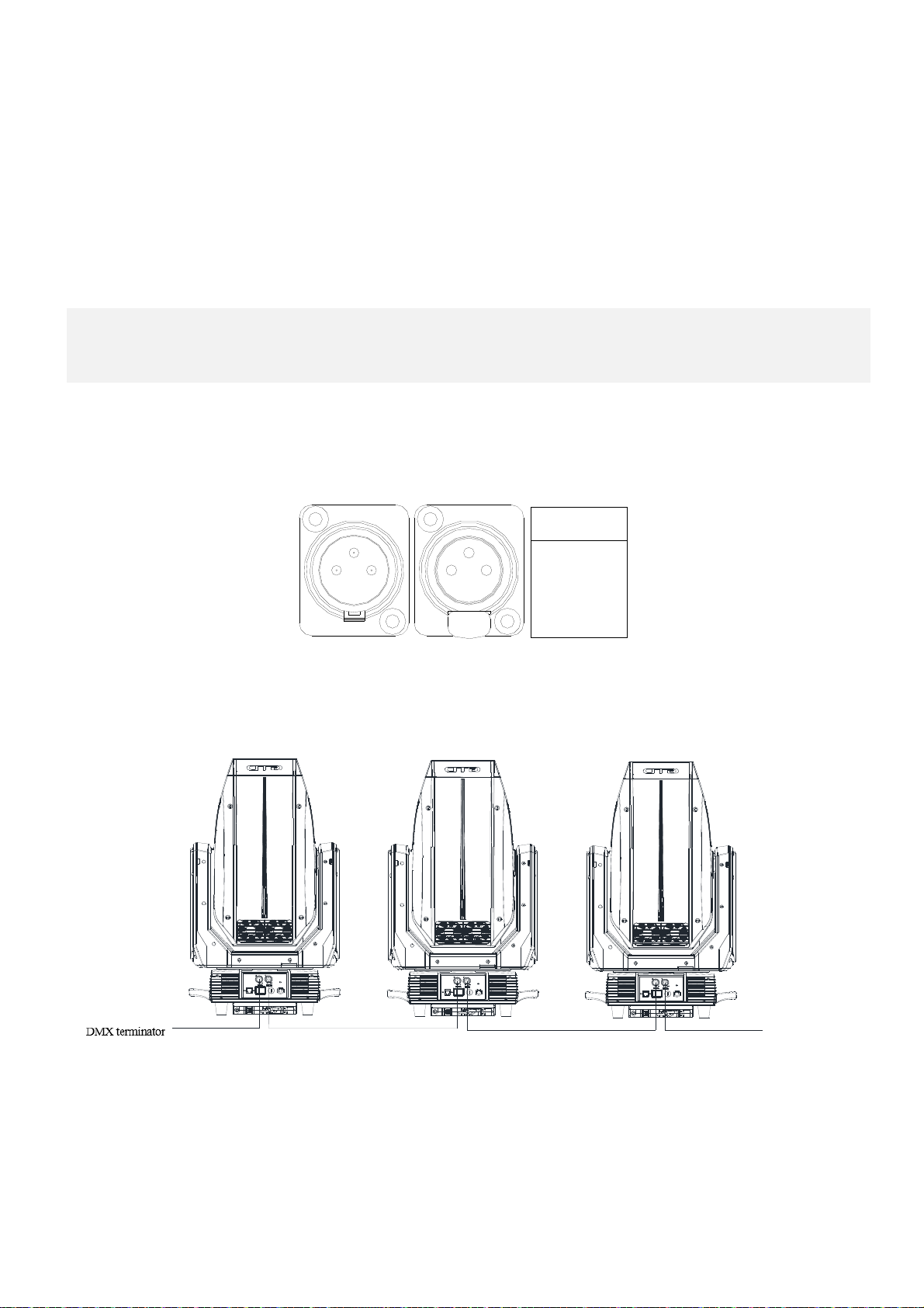
5.1 Power connection .................................................................................................................................................... 7
5.2 Control connection .................................................................................................................................................. 7
5.3 Testing..................................................................................................................................................................... 7
6. Control panel...............................................................................................................................................................8
6.1 Panel instruction...................................................................................................................................................... 8
7. Technical specification................................................................................................................................................9
8. Gobos and colors.......................................................................................................................................................12
8.1 Gobo specification................................................................................................................................................. 12
8.2 Gobos .................................................................................................................................................................... 12
8.3Colors ..................................................................................................................................................................... 13
8.4 Cutting effect......................................................................................................................................................... 13
9. Menu structure..........................................................................................................................................................14
10. DMX protocol..........................................................................................................................................................16
11. System wiring diagram...........................................................................................................................................28
12. Maintenance and Troubleshooting........................................................................................................................29
12.1 Cleaning and maintenance .................................................................................................................................. 29
12.2 Troubleshooting .................................................................................................................................................. 29
13. Spare parts list ........................................................................................................................................................32

1
1.Safety instructions
Before using the fixture, read the latest version of the product user manual, paying particular attention to
the safety instructions. Please check www.gtd-lighting.com for the latest revision/update of the user manual.
Indoors use only.
m
ta
tc
The manufacture of this fixture, are not responsible for damages, resulting from misuse of this fixture,
due to the disregard of the information printed in this user manual.
DANGER!
Hazardous voltage. Risk of lethal or severe electric shock
WARNING!
Wear protective eyewear. Never look directly into the light source.
WARNING!
Burn hazard. Hot surface. Do not touch.
Only to direct mounting on non-combustible surfaces.
Minimum distance to lighted objects.
Replace all cracked glass shields.
Maximum ambient temperature.
Maximum temp of the external surface.

2
General guidelines
The protection rating of this product IP20.
Never open this fixture while it is in use.
The fixture should be kept clean. DO NOT operate the fixture in extreme heat or dusty environments. Avoid contact
with chemical liquid.
Minimum distance to lighted objects must be 16.4 feet (5m).
Maximum temp of the external surface 158˚F (70˚C).
Maximum ambient temperature 113˚F (45˚C).
Minimum distance of inflammable materials from the surface 1.6 4feet (0.5m).
Lamp should be replaced if damaged or distorted in shape due to extreme heat.
Cover, prism or LCD Menu Function Display with visible damages such as cracks or scratches must be replaced to
ensure performance of the fixture.
Disconnect the fixture from power before changing any parts or accessories.
Basic insulation should be maintained between the controllable device and the product power supply.
Make sure that the installation area can hold a minimum point load of 10 times the weight of all installed fixtures,
clamps, cables, auxiliary equipment, etc. Make sure that the cover, clamps and locks are undamaged. Certified safety
cables must always be used when installing the fixture.
The fixture is only intended for installation, operation and maintenance by qualified professional. Instructions stated in
the manual must be complied.
The fixture must be kept in a well-ventilated place at least 50 cm away from any wall surface. Check if the fans or
ventilation openings are unblocked.
This fixture uses discharge lamp. Avoiding reduce the lamp’s life, wait at least 15 minutes after powering off to allow
the unit to cool down before handling.
To ensure operational safety, broken or damaged cables and light source can only be fixed or replaced by certified
technicians, certified local distributors or the manufacturer.
Do not stick filters or other materials onto the lens. Do not modify the fixture or install other than GTD manufactured
parts.
For questions regarding safety operation, please contact our technical personnel or call the service hotline
+862061808296.

3
2. Production instructions
2.1 Dimensions
449
[17.66"]
805
[31.63"]
442
[17.35"]
588
[23.11"]
286
[11.24"]
287
[11.27"]
142
[5.59"]
625
[24.57"]
270°
270°
270°

4
2.2 Fixture overview
Pan-tilt frame
Base module
Lamp holder assembly
CMY CMY
CTO
{
Color & gobo wheels module
Framing blade system
Cap as-lamp
{objective
Zoom
Focus
Atomization
Prism
2.3 Accessories
Item Qty Unit Remark
User Manual 1 Pc --
Safety cable 2 Pcs Φ5*60cm 7*19 pc with hook Material:Steel
3‐pinssignalline1Set--

5
3. Packing and shipping
3.1 Protection lock
Pan and tilt locks are equipped to ensure safe transportation.
The horizontal axis has 8 locking points and the vertical axis has 4 locking points.
3.2 Unpacking
Notes
All products are quality controlled before they dispatched to customers. If the fixture is damaged during delivery,
the customer must notify the shipper and manufacturer to file a damage insurance claim. Photographic evidence
of the damage must be provided.
Flight- Case (specification:645*505*715mm): One set in a box. Uncover the flight-case and remove the plastic
packing bags. Hold the handles of the fixture firmly and take it out carefully.
Cardboard box (specification:744*715*525mm):One set in a box. Open the box and take out the whole set of
packaging foam which are contained both the fixture and its accessories. Remove the foam from the top, put
away the accessories, and then take out the fixture wrapped in the plastic bag.
Notes
Check if the pan and tilt are locked before connecting the fixture to power.
3.3 Packing after use
1. Switch off the fixture and wait for at least 5 minutes before disconnecting it from AC power. Cool down the
fixture for at least 15 minutes before packing.
2. Lock pan and tilt.
3. Flight case: Wrap the fixture in plastic bags. Gripping the handle and then place it in the flight case along with
all the accessories carefully. Close the cover lid. The wrap page are not allowed over 3 layers. Do not upside
down.
4. Cardboard box: Wrap the fixture in plastic bags. Put it in the packaging foam along with all the accessories.
Place the other set of packaging foam on top then put it carefully in the cardboard box.
Tilt Lock
Pan Lock

6
4. Installation
4.1 Clamps installation
The fixture can be placed on the stage or mounted on the truss which faces any direction. Attach the clamps to the mounting
position on the base of the fixture.
Warning:Use two clamps when mounting the fixture. Turn the screws attached to each clamp a 1/4 turn clockwise to lock.
Always remember to use the safety cable which goes through the mounting hole on the base. Do not attach the safety cable
on the handle.
4.2 Device installation
1. Make sure there is no damage on the clamps or safety cables before installation.
2. The clamp is mounted on the chassis of the fixture. Horizontally insert the clamp into the mounting holes of the chassis.
Fasten the clamp tightly by a 1/4 turn clockwise. Fix another clamp in the same way.
3. If equipped with folding clamp, please raise the clamp and rotate it to adjust the opening direction.
4. Check if pan.
832
[32.69"]
331
[13.02"]
165
[6.46"]

7
5. Power/ Control connection
5.1 Power connection
Connection method:
L (Live) Brown wire
E (Earth) Yellow / Green bi-color wire
N (Neutral) Blue wire
The voltage and frequency of the power source must be in compliance with the ones marked on the fixture. It is
strongly recommended that each fixture are to be connected to the power source separately so that they can be
switched on / off individually.
5.2 Control connection
The fixture has 3-pin XLR connectors for DMX data input and output as shown below. Connection between the console and
fixture, and between fixtures must be made with 2 core screened DMX signal cable. Maximum connecting distance of
signal cable is 150 meters. Additional DMX512 signal-amplifier is recommended for longer distance.
1
3
22
3
1
DMX 512
1:Ground
2:-
3:+
Connect the Console’s DMX OUTPUT to the first fixture’s DMX INPUT, then the first fixture’s DMX OUTPUT to the
second fixture’s DMX INPUT and so on. It is recommended not to connect more than 32 units on a single DMX universe.
On the last fixture’s output connect a DMX terminator. (The terminator is a 3-pin XLR connector with a 1/2W and 120Ω
resistor between the pin 2 and pin 3) as shown below:
5.3 Testing
Connect the fixture to AC power. Check if the lamp is on and the fixture is independently controllable before putting into
operation.
信号终端 输入 输出 输入 输出 输入 输出 控台
Input Output OutputInput Input Output
Console

8
6. Control panel
6.1 Panel instruction
The control panel features touch-sensitive buttons and LCD digital display for quick and easy setup of address
code and functions menu.
Press MENU to view or select the function, press UP or DOWN to view or select the function menu.
Press ENTER to choose a function and enter into corresponding submenu. Each menu represents a specific
function of the fixture.
Press ENTER to save the changes or enter into the submenu, then press UP or DOWN to change the value of the
selected function (increase or decrease).
Press MENU to return to the previous menu or exit.
LED indicator light: RED light.

9
7. Technical specification
Optical
Light source: LED 1000W
Expected average lifetime: 20000 h
Lumens: largeangle:35000lm
Zoom range:5°~50°Linear high speed zoom,the spot is uniform and consistent in any range
CRI:Ra≥70,plus filter can reach more than 90,;optional Ra≥95 version
Focus:multi-point focus, focus from5 meters to infinity tracking
Prism: 1 four-prism
Frost: 1-independent frost effect
Gobo
Rotating gobo wheel: 1 interchangeable gobo rotator, 6 optional pattern pieces, CW/CCW rotation, variable speed.
Fixed gobo wheel: 1 fixed gobos +7 pattern pieces +open, CW/CCW rotation, variable speed.
Effect gobo wheel: One effect wheel can rotate graphics in both directions, and can be combined with other patterns
to produce dynamic effects such as flame, water grain, wave, Buddha cloud and so on.
Cutting wheel: 1 cutting wheel capable of rotating 90 °; 4 mobile cutting molding pieces; Various geometric figures
of different sizes can be generated, and 4 cutting pieces can achieve the whole cutting effect.
Color
Color wheel: 6 color gel and open gobo, “Rainbow effect” in both directions
CMY: infinite color mixed
CTO:6500K-2700K
Electrical
Power input, nominal: AC 100-240V 50/60Hz
Max. Power consumption:1334W
Max current: 13.06A PF:0.97
Main fuse: 250V / 15A
Power input: self-contained power cord
DMX data input/output: Chassis 3-pin
Control and programming
Control channels (DMX): 36/33/52
Protocol: DMX-512, RDM
Display: LCD
Physical / Installation
Weight: 83.78bs. (38kg),including lamp hook
IP rating: IP20
Material: Aluminum, copper, steel, plastic, iron
Mounting points: 2 fixed folding lamp hook + attachment points for safety wire

10
Dynamic effects
Pan/Tilt movement: 540˚/270˚,adopting a function which resets 32bit accurately and automatically
Strobe: 1-20Hz
Dimmer: 0-100%, mechanical linear dimming
Thermal
Operating range: 14˚F to 113˚F (-10˚C to 45˚C)
Startup range: -13˚F to 113˚F (-25˚C to 45˚C)
Storage range: -39.9˚F to 140˚F ( -40˚C to 60˚C)
Cooling: Active fan
Humidity: ≤85%
Certification and Safety
EMC: EN 55103-1:2009, EN 55103-2:2009, EN 61000-3-2:2006+A2:2009, EN 61000-3-3:2013,
GB/T 17743-2007, GB 17625.1-2012
Safety: EN 60598-2-17:1989/A2:1991, GB 7000.1-2015, GB 7000.217-2008
Photometric
0
5m
10m
15m
20m
25m
5m
10m
15m
20m
25m
(5° )
(50°)
(m/ft.) 0 5/16.40
Φ0.88/2.89 Φ1.32/4.33 Φ1.76/5.77
Φ4.66/15.29 Φ9.32/30.58 Φ13.98/45.87 Φ18.64/61.15
10/32.81 15/49.21 20/65.62
16500 7970 40105° 2730 761 612 26950°
5°50°
Ra≥70
llluminance(LUX)
Distance
B
eam diameter(m/ft.)
B
eam diameter(m/ft.)

11
Other features
Enhanced stability of the fixture due to the wide input voltage AC/DC switching power supply which both reduces the
impact of power and voltage fluctuations, and removes the restriction of voltage and frequency variations in different
countries.
Automatic energy saving: when the shutter or CMY is closed, power consumption will be reduced automatically with
the photoelectric tracking induction technology.
Sleep mode: uses the most advanced technology to activate sleep mode remotely. When the fixture is disconnected
from signal, the sleep mode is enabled automatically to make it more stable and safer. Sleep time can be customized.
Power setting: built-in continuous rechargeable battery, allowing setting functional data via LCD interface without
power connection.
Communications Design:DMX wired/wireless transmission, bidirectional-control technology, upgrade the software
quickly and conveniently by using DMX cable.
Thermal design: The wind drainage and intelligent temperature monitoring technology can monitor lighting’s state: on
/off. It can adjust the thermal design by the position’s temperature of lighting so that the temperature can be controlled.
0
5m
10m
15m
20m
25m
5m
10m
15m
20m
25m
(5° )
(50°)
(m/ft.) 0 5/16.40
Φ0.88/2.89 Φ1.32/4.33 Φ1.76/5.77
Φ4.66/15.29 Φ9.32/30.58 Φ13.98/45.87 Φ18.64/61.15
10/32.81 15/49.21 20/65.62
11590 5600 28165° 1980 552 443 19850°
5°50°
Ra≥95
llluminance(LUX)
Distance
Beam diameter(m/ft.)
B
eam diameter(m/ft.)

12
8. Gobos and colors
8.1 Gobo specification
All patterns are made onto the metal gobos, and can be customized according to user’s requirement.
The customized size is as below:
Gobo material Outer dimension Effective dimension Thickness
Glass gobo Φ27mm Φ22mm 1.1mm
Glass gobo Φ27mm Φ27mm 3.5mm
Gobo material: Glass
8.2 Gobos
1
2
3
4
5
6
7
1
2
3
4
5
6

13
8.3 Colors
Color wheel CMY/CTO
8.4 Cutting effect
some effect
1.CPIfilter2.Red3.Orange
4.Green5.Yellow6.Blue
1
4
2
3
5
6C色
M色
Y色
CTO

14
9. Menu structure
Level 1 Level 2 Level 3 Level 4 Info
Run
setting
Address
Setting
Value Display
Auto-Program
Address: 001~
XXX
Pan ……,All,Off
Master /Slave
Setting the DMX address
Display the channel value
Run auto program in master or slave
Device
Info
Time Info Since power on
Total Time
Last Time
Lamp On Time
Lamp Off Time
Last Time Code
Clear Last Time
Lamp Time Code
Clear Lamp Time
XXXXXX Hour
XXXXXX Hour
XXXXXX Hour
XXXXXX Hour
XXXXXX Minute
Password: XXX(88)
Yes /No
Password: XXX(111)
Yes /No
Since power on time
Product total run time
Last product run time
Lamp on time
Lamp close time
Clear last time password
Clear last time
Clear lamp time password
Clear lamp time
Temperature Temperature1/2/3 XXX ’C/’F Body temperature
Fans’ Err Ok/Err/No Show fans’ status
Err Inf No/... Show this device’s status
Software
Ver si on
X.X The software version
System
Setting
Status Setting Console Set Addr
No Signal Status
Pan Reverse
Tilt Reverse
Pan Scan Degree
Scan Feedback
Scan Speed
Standby Time
Enable/Disable
Off/Hold/Auto/Music
Enable/Disable
Enable/Disable
360/540
Enable/Disable
Quick/Middle/Low/Slow
Disable/1~20~99 Min
Address can be changed by console
The status while no signal
Pan Reverse
Tilt Reverse
Pan Scan Degree
Scan Feedback
Change the scan speed
Standby time
Fan Speed Smart Control
High Speed
Low Speed
Auto fans speed
Fans high speed
Fans low speed
Display
Setting
Backlight Time
Key Lock
Lightness
Language
Screen auto
1~80 Min/Disable
Enable/Disable
15~100% 80%
Chinese/English
off/on/auto
Backlight off time
Press <menu> 3s to unlock
Back lightness of screen
Change the language
Screen change Setting
Temperature
Unit
Celsius
Fahrenheit
Temperature unit
Val ue D efa ul t Pa n… … Pan =XXX The default value
Wireless Dev Wireless Off
Wireless On
Wireless Trans.
Wireless Reset
Wireless off
Wireless on
Wireless transfer DMX data to another
Wireless reset
Restore Yes /No Restore to default value

15
Default
Product Select - Password- GTD xxx xxx xxx Product Name Select
Reset System Reset
Scan Reset
ColorReset
Gobo Reset
Other Reset
System reset
Pan and tilt motor reset
Color motor reset
All gobo motor reset
All other motor reset
Channel
Adjust
Test Mode Pan…… Every channel test
Manual Mode Pan:Pan =XXX:Manual control
Adjust Mode Input Password
Pan:
Password=XXX(99)
Pan=XXX:
The password of adjust mode
Fixed all begin position
Focus Mode Input Password
Pan:
Password=XXX(99)
Pan=XXX:
The password of adjust mode
Fixed all begin position
Channel
Setting
Channel Mode Standard Mode
Simplified Mode
Extended Mode
Custom Mode 1
Custom Mode 2
Custom Mode 3
Standard channel mode
Simplified channel mode
Extended channel mode
Custom channel mode 1
Custom channel mode 2
Custom channel mode 3
Set Custom
Mode1
Set Custom
Mode2
Set Custom
Mode3
Max Channel
Pan:
Channel = XX
Pan = CH01:
Change the channel order
Program
Edit
Select Prog. Program Unit 1
Program Unit 2
Program Unit 3
Program 1 ~10
Program 1 ~ 10
Program 1 ~ 10
Choose build-in program for slave 1
Choose build-in program for slave 2
Choose build-in program for slave 3
Program Edit Auto-Program1:
Auto-Program10
Run
Step 1=Scene xxx
Step 8=Scene xxx
Choose the scene for program 1:
Choose the scene for program 10
Scene Edit Scene
Edit:001-250
Pan,……Pan=xxx
Scene Time=xxx
Input By Console
Edit the channel DMX
Edit the scene time
Get scene DMX form console
Record Scene Scene XX->XX Record scene form console
*Settings highlighted in light grey are default values

16
10. DMX Protocol
Standard
DMX mode
Name DMX value DMX percentage Function Default
DMX
Value
Standard
(36ch)
1 Strobe/
Shutter
0 31 0.0% 12.2% Closed
0(0%)
32 63 12.5% 24.7% Open
64 127 25.1% 49.8% Synchronous strobe from slow to fast
128 159 50.2% 62.4% Open
160 223 62.7% 87.5% Random strobe from slow to fast
224 255 87.8% 100.0% Open
2 Intensity 0 255 0.0% 100.0% No light →Full light 0(0%)
3 Cyan 0 255 0.0% 100.0% White →Full cyan 0(0%)
4 Magenta 0 255 0.0% 100.0% White →Full magenta 0(0%)
5 Yellow 0 255 0.0% 100.0% White →Full yellow 0(0%)
6 CMY color
macro
0 15 0.0% 5.9% CMY color macro off
0(0%)16 135 6.3% 52.9%
CMY synchronous color from slow to
fast
136 255 53.3% 100.0% CMY random color from slow to fast
7 CTO 0 255 0.0% 100.0% White →Full CTO 0(0%)
8 Color wheel
0 13 0.0% 5.1% Open
0(0%)
14 32 5.5% 12.5% Color 1
33 51 12.9% 20.0% Color 2
52 70 20.4% 27.5% Color 3
71 89 27.8% 34.9% Color 4
90 108 35.3% 42.3% Color 5
109 127 42.8% 49.8% Color 6
128 187 50.2% 73.3% Color continous rotation CW from
slow to fast
188 195 73.7% 76.5% Stop
196 255 76.9% 100% Color continous rotation CCW from
slow to fast
9 Gobo wheel
(static)
0 15 0.0% 5.9% Open
0(0%)
16 23 6.3% 9.0% Gobo 1
24 31 9.4% 12.1% Gobo 2
32 39 12.5% 15.3% Gobo 3
40 47 15.7% 18.4% Gobo 4
48 55 18.8% 21.5% Gobo 5
56 63 21.9% 24.7% Gobo 6
64 71 25.1% 27.8% Gobo 7

17
DMX mode
Name DMX value DMX percentage Function
Default
DMX
Value
Standard
(36ch)
9 Gobo wheel
(static)
72 79 28.2% 31.0% Gobo 1 shake
0(0%)
80 87 31.4% 34.1% Gobo 2 shake
88 95 34.5% 37.3% Gobo 3 shake
96 103 37.7% 40.4% Gobo 4 shake
104 111 40.8% 43.5% Gobo 5 shake
112 119 43.9% 46.7% Gobo 6 shake
120 127 47.1% 49.8% Gobo 7 shake
128 187 50.2% 73.3% Gobo wheel continous rotation CW
from slow to fast
188 195 73.7% 76.4% Stop
196 255 76.9% 100.0%
Gobo wheel continous rotation CCW
from slow to fast
10
0 13 0.0% 5.1% Open gobo
0(0%)
Rotating gobo
wheel
14 23 5.5% 9.0% Gobo 1
24 33 9.4% 12.9% Gobo 2
34 43 13.3% 16.9% Gobo 3
44 53 17.3% 20.8% Gobo 4
54 63 21.2% 24.7% Gobo 5
64 73 25.1% 28.6% Gobo 6
74 82 29.0% 32.2% Gobo 1 shake
83 91 32.5% 35.7% Gobo 2 shake
92 100 36.1% 39.2% Gobo 3 shake
101 109 39.6% 42.8% Gobo 4 shake
110 118 43.1% 46.3% Gobo 5 shake
119 127 46.7% 49.8% Gobo 6 shake
128 187 50.2% 73.3% Gobo wheel continous rotation CW
from slow to fast
188 195 73.7% 76.5% Stop
196 255 76.9% 100.0%
Gobo wheel continous rotation CCW
from slow to fast
11
Gobo
rotating/positi
oning gobo
wheel
0 127 0.0% 49.8% Gobo rotation/positioning
0(0%)
128 187 50.2% 73.3% Gobo continous rotation CCW from
slow to fast
188 195 73.7% 76.5% Stop
196 255 76.9% 100.0% Gobo continous rotation CW from
slow to fast
12 0 255 0.0% 100.0% Gobo rotation/positioning, fine (LSB) 0(0%)
13 Blade 1 0 255 0.0% 100.0% White →Full Blade 1 0(0%)
14 Blade 2 0 255 0.0% 100.0% White →Full Blade 2 0(0%)
Table of contents
Other GTD Lighting Equipment manuals

GTD
GTD GTD-330 N BSW User manual

GTD
GTD GTD-LZ354P User manual

GTD
GTD GTD-470NBSW User manual

GTD
GTD GTD-L2016P User manual

GTD
GTD GTD-LM1000 II BSWP User manual

GTD
GTD GTD-1400 II PROFILE User manual

GTD
GTD GTD-LP200 User manual

GTD
GTD GTD-F3 II BSW User manual

GTD
GTD GTD-F10 II PROFILE User manual

GTD
GTD GTD-LM660 II Profile User manual
Popular Lighting Equipment manuals by other brands

Future light
Future light EYE-19 HCL ZOOM user manual

Capital Play
Capital Play Trampoline MagicNight Lights Installation Manual & Safety Instructions

Viabizzuno
Viabizzuno clv 1 Installing instructions

Flash
Flash LED NEW EFFECT LIGHT user manual

SWIT Electronics
SWIT Electronics CL-M100D user manual

Ecco
Ecco ED3789 Installation and operation instruction