GTD GTD-1400 II PROFILE User manual

1400W II Moving Head
User Manual
GTD-1400 II PROFILE

©2019 GTD all rights reserved. Information, specifications, diagrams, images, and instructions herein are subject to
change without notice. GTD logo and identifying product names and numbers herein are trademarks of GTD.
Copyright protection claimed includes all forms and matters of copyrightable materials and information now allowed
by statutory or judicial law or hereinafter granted. Product names used in this document may be trademarks or
registered trademarks of their respective companies and are hereby acknowledged. All non-GTD brands and product
names are trademarks or registered trademarks of their respective companies.
GTD and all affiliated companies hereby disclaim any and all liabilities for property, equipment, building, and electrical
damages, injuries to any persons, and direct or indirect economic loss associated with the use or reliance of any
information contained within this document, and/or as a result of the improper, unsafe, insufficient and negligent
assembly, installation, rigging, and operation of this product.
P/N:1502010250A
Guangzhou GTD Lighting Technology Co., Ltd. | 27 Fu Yuan Yi Road, Guangzhou 510805, P.R.China
+86-20-61808296 | +86-20-61812282 fax | www.gtd-lighting.com contact@gtd+china.com
|

1.Table of contents
1.Contents....................................................................................................................................................3
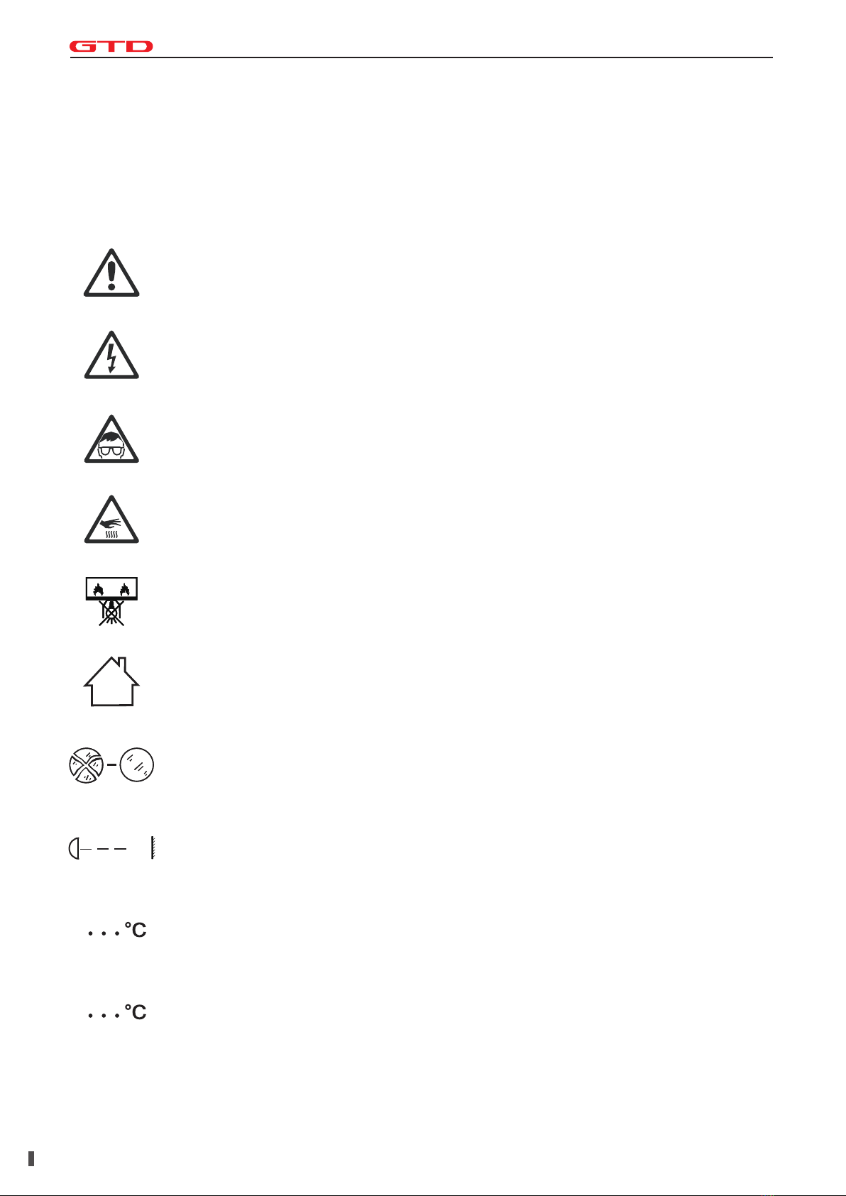
2.Safety instructions...................................................................................................................................4
3.Product introductions..............................................................................................................................6
3.1 Dimensions .............................................................................................................................................6
3.2 Fixture overview ......................................................................................................................................7
3.3 Accessories.............................................................................................................................................7
4.Packing and shipping...............................................................................................................................8
4.1 Protection lock.........................................................................................................................................8
4.2 Unpacking................................................................................................................................................8
4.3 Packing after use.....................................................................................................................................8
5.Installation................................................................................................................................................9
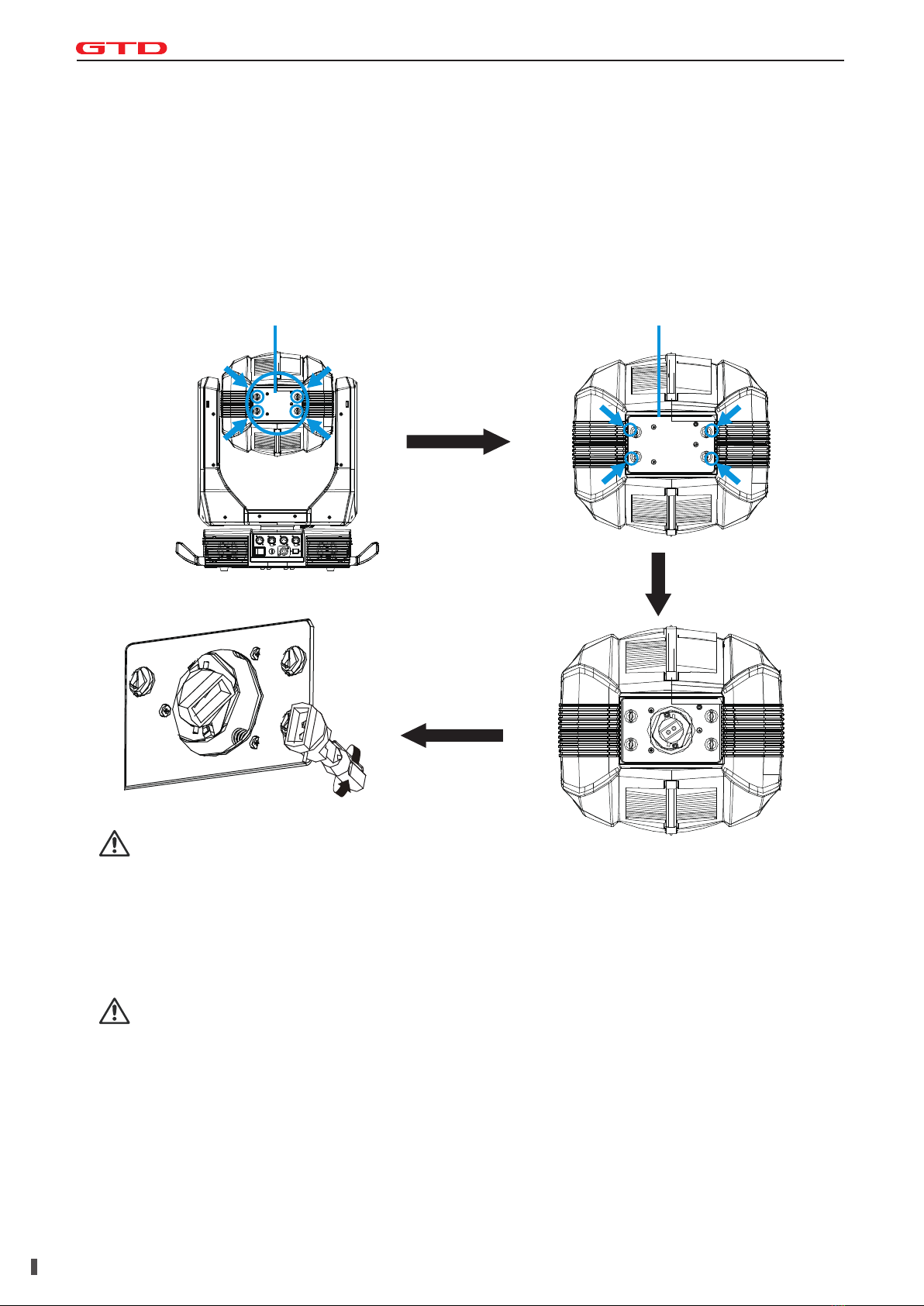
5.1 Clamps installation...................................................................................................................................9
5.2 Device installation....................................................................................................................................9
5.3 Lamp fitting and adjustment...................................................................................................................10
6.Power / Control connection...................................................................................................................11
6.1 Power connection..................................................................................................................................11
6.2 Control connection.................................................................................................................................11
6.3 Testing...................................................................................................................................................11
7.Control panel..........................................................................................................................................12
7.1 Panel instruction....................................................................................................................................12
8.Technical specification..........................................................................................................................13
9.Gobos and colors...................................................................................................................................15
9.1 Gobo specification.................................................................................................................................15
9.2 Gobos....................................................................................................................................................15
9.3 Colors....................................................................................................................................................15
10.Menu structure.....................................................................................................................................16
11.DMX protocol........................................................................................................................................18
12.System wiring diagram........................................................................................................................24
13.Maintenance and Troubleshooting.....................................................................................................34
13.1 Troubleshooting...................................................................................................................................34
13.2 System wiring diagram.........................................................................................................................35
14 Spare parts list......................................................................................................................................36
03GTD
Lighting

Before using the fixture, read the latest version of the product user manual, paying particular attention to
the safety instructions. Please check www.gtd-lighting.com for the latest revision/update of the user
manual.
The manufacture of this fixture, are not responsible for damages, resulting from misuse of
this fixture, due to the disregard of the information printed in this user manual.
DANGER!
Hazardous voltage. Risk of lethal or severe electric shock.
WARNING!
Burn hazard. Hot surface. Do not touch.
WARNING!
Wear protective eyewear. Never look directly into the light source.
Only to direct mounting on non-combustible surfaces.
Replace all cracked glass shields.
INDOORS USE ONLY!
Do not expose fixture for rain and moisture.
Minimum distance to lighted objects.
Maximum ambient temperature.
Maximum temp of the external surface.
2.Safety instructions
m
ta
tc
GTD-1400 II PROFILE
04GTD
Lighting

General guidelines
05GTD
Lighting
Never open this fixture while in use.
The fixture should be kept clean. DO NOT operate the fixture in extreme heat or dusty
environments. Avoid contact with chemical liquid.
This fixture is a professional light effect designed for INDOOR / DRY LOCATIONS ONLY on
stage, in nightclubs, theatres, etc.
Minimum distance to lighted objects must be 16.4feet (5m).
Maximum temp of the external surface 302˚F (150˚C).
Maximum ambient temperature 113˚F (45˚C).
Minimum distance of inflammable materials from the surface 1.6 feet (0.5m).
Lamp should be changed if damaged or distorted in shape due to extreme heat.
Cover, prism or LCD Menu Function Display with visible damages such as cracks or scratches
must be replaced to ensure performance of the fixture.
Disconnect the fixture from power before changing any parts or accessories.
Basic insulation should be maintained between the controllable device and the product power
supply.
Make sure that the installation area can hold a minimum point load of 10 times the weight of all
installed fixtures, clamps, cables, auxiliary equipment, etc. Check that the cover, clamps and locks
are undamaged. Certified safety cables must always be used when installing the fixture.
The fixture is only intended for installation, operation and maintenance by qualified professional.
Instructions stated in the manual must be complied.
The fixture must be kept in a well-ventilated place at least 50 cm away from any wall surface.
Check if the fans or ventilation openings are unblocked.
This fixture uses discharge lamp. To avoid reducing the lamp’s life, wait at least 15 minutes after
powering off to allow the unit to cool down before handling.
Broken or damaged cables and light source can only be fixed or changed by certified
technicians, certified local distributors or the manufacturer to ensure operational safety.
Do not stick filters or other materials onto the lens. Do not modify the fixture or install other than
GTD manufactured parts.
For questions regarding safety operation, please contact our technical personnel or call the
service hotline +8620 61808296.
GTD-1400 II PROFILE

3.1 Diamension
3.Production instructions
06GTD
Lighting
GTD-1400 II PROFILE
446mm
(17.6″)
634mm
(25″)
421mm
(16.6″)
570mm
(22.4″)
818mm
(32.2″)
546mm
(21.5″)
297mm
(11.7″)
358mm
(14.1″)

3.2 Fixture overview
3.3 Accessories
Item Qty Unit Remark
User Manual 1 --
Pc
Clamps
2
Set
20-63mm
Safety cable
1
Pc
φ5*60cm 7*19pc with hook Material:Steel
07GTD
Lighting
SN
1
2
3
4
5
6
7
8
9
10
Item
Frost module
Head module
Prism module
Tilt lock
Framing blade system
CMY
Lamp-holder assembly
Pan-tilt frame
Pan lock
Base module
11 LCD display
10
11
GTD-1400 II PROFILE

Pan and tilt locks are equipped to ensure safe transportation.
PAN: 4 lock positions are located evenly on the Pan.
TILT: 5 lock positions are located on left and right side of the Tilt with the third one in the center.
4.1 Protection lock
Notes
All products are quality controlled and checked for any faults before they are dispatched to customers. If
the fixture is damaged during delivery, the customer must notify the shipper and manufacturer to file a
damage insurance claim. Photographic evidence of the damage must be provided.
Flight-Case
Open the cover of the flight-case and remove the plastic packing bags. Hold the handles of the fixture
firmly and take it out carefully.
Cardboard box
Open the box and take out the whole set of packaging foam which contains both the fixture and its
accessories. Remove the foam from the top, put away the accessories, and then take out the fixture
wrapped in the plastic bag.
Notes
Check if the pan and tilt are unlocked before connecting the fixture to power.
4.2 Unpacking
1. Switch off the fixture and wait for at least 5 minutes before disconnecting it from AC power. Cool down
the fixture for at least 15 minutes before packing.
2. Lock pan and tilt.
3. Flight case: Wrap the fixture in plastic bags. Hold it by the handles, and then carefully place it inside
the flight case along with all the accessories. Close the cover. Only 2 layers are allowed when piling up
the flight cases. Do not upside down.
Cardboard box: Wrap the fixture in plastic bags. Put it in the packaging foam along with all the
accessories. Place the other set of packaging foam on top then carefully put it inside the cardboard box.
4.3 Packing after use
4.Packing and shipping
08GTD
Lighting
GTD-1400 II PROFILE
Pan Lock Tilt Lock

The fixture can be placed on the stage or mounted on the truss facing any direction. Attach the
clamps to the mounting position on the base of the fixture.
Warning
Use two clamps when mounting the fixture. Turn the screws attached to each clamp a 1/4 turn
clockwise to lock. Always remember to use the safety cable which goes through the mounting hole on
the base. Do not attach the safety cable on the handle.
5.1 Clamps installation
1. Make sure there is no damage on the clamps or safety cables before installation.
2. The clamp is mounted on the chassis of the fixture. Horizontally insert the clamp into the
mounting holes of the chassis. Fasten the clamp tightly by a 1/4 turn clockwise. Fix another
clamp in the same way.
3. Check if pan and tilt are unlocked before connecting the unit to AC power.
5.2 Device installation
5.Installation
09GTD
Lighting
GTD-1400 II PROFILE
Safety cable mounting position
ClampClamp

1. Disconnect the fixture from AC power. Cool down the fixture. Set the Tilt lock in a horizontal position.
2. Use a flathead screwdriver to loosen the back cover. Remove the lamp by anticlockwise rotating and pull
it out.
3. Push the light bulb to the hole on the reflector. Rotate 1/4 turn clockwise until it is securely fastened.
4. Observe the outlet of the reflector when pushing.
5. After fixing the lamp, install the back cover.
5.3 Lamp fitting and adjustment
10GTD
Lighting
Back cover Back cover
Remove the back cover
Enlarged diagram
Push the light bulb to the hole,
rotate 1/4 turn clockwise
until it is securely fastened.
Note
The fixture is equipped with Metal Halide 1400W short arc discharge lamp, which is featured with high
efficiency and short-arc characteristic, such as a stable 6000K color-temperature and average lifespan of
750hrs.
The PGJ28/PGJX28 single ended lamp holder must be applied to ensure proper installation.
Note
Fitting another type of lamp will cause potential damage to the fixture. Change the lamp before it reaches
its lifespan. Read the guidelines in the package carefully when fixing the lamp.
To avoid any impact on the beam, do not touch the bulb with your bare hands. The lamp must be kept
clean with the use of the clean paper contained in its package.
GTD-1400 II PROFILE

Connection method:
L (Live) Brown wire
E (Earth) Yellow / Green bi-color wire
N (Neutral) Blue wire
The voltage and frequency of the power source must be in compliance with the ones marked on
the fixture. It is strongly recommended that each fixture are to be connected to the power source
separately so that they can be switched on / off individually.
6.1 Power connection
The fixture has 5-pin and 3-pin XLR connectors for DMX data input and output as shown below.
Connection between the console and fixture, and between fixtures must be made with 2 core screened
DMX signal cable. Maximum connecting distance of signal cable is 150 meters. Additional DMX512
signal-amplifier is recommended for longer distance.
Connect the Console’s DMX OUTPUT to the first fixture’s DMX INPUT, then the first fixture’s DMX
OUTPUT to the second fixture’s DMX INPUT and so on. It is recommended not to connect more than 32
units on a single DMX universe. On the last fixture‘s output connect a DMX terminator. (The terminator is
a XLR connector with a ¼ W and 120Ω resistor between the pin 2 and pin 3) as shown below:
6.2 Control connection
Connect the fixture to AC power. Check if the lamp is on and the fixture is independently
controllable before putting into operation.
6.3 Testing
6.Power/ Control connection
11GTD
Lighting
Console Input Output Input Output Input Output DMX terminator
GTD-1400 II PROFILE
12
3
12
3
DMX 512
1:Ground
2:—
3:+
15
324
15
324
DMX 512
1:Ground
2:—
4:Reserved
5:Reserved
3:+

The control panel features touch-sensitive buttons and LCD digital display for quick and easy setup
of address code and functions menu.
Press UP or DOWN to view or select the function menu.
Press ENTER to choose a function and enter into corresponding sub menu. Each menu represents
a specific function of the fixture.
Press ENTER to select the specific function and save the changes or enter into the submenu, then
press UP or DOWN to change the value of the selected function (increase or decrease).
Press MENU to return to the previous menu or exit.
LED indicators:
Power on: RED power LED indicator on
7.1 Using the control panel
7.Control panel
12GTD
Lighting
GTD-1400 II PROFILE
GTD-1400 II PROFILE

Light source: OSRAM 1400/PS Brilliant
Expected average lifetime: 750 h
Color temperature correction: 6000K~2700K
Zoom: 5º-55º
Spot uniformity:≥80%
CRI:Ra≥96
Total Luminous: 33595 lumen
Focus: High-precision glass lenses, electronic linear HD focus
Prism: 1-facet prism,CW/CCW rotation, variable speed
Frost: 1-independent frost effect
Optical
Power input, nominal: AC 200-240V, 50/60Hz
Max. Power consumption: 1659W, max current: 7.86A, PF: 0.997
Power supply unit: Auto-ranging electronic SMPS
Main fuse: 250V/6.3A
Ballast: Electronic
AC power: Neutrik powerCon
DMX data input/output: Chassis 3-pin、5-pin Neutrik XLR (in/out)
Electrical
Color wheel: 7 colors + open, split color, CW/CCW rotation,“Rainbow effect”in both directions
Color
Control channels (DMX): 37/34/54
Protocol: DMX-512
Display: Graphic LCD backlit
Control and programming
Weight: 45.7Kg (101lbs.)
IP rating: IP20
Material: Aluminum, steel, plastic
Mounting points: Four quarter-turn locking points + attachment points for safety wire
Physical / Installation
Rotating gobo wheel: 5 interchangeable gobos + open, indexing, CW/CCW rotation, variable speed
Fixed gobo wheel: 7 gobos + open, CW/CCW rotation, variable speed
Gobo outside diameter: 36 mm
Max. Image diameter: 26mm
Max. Thickness: 2.6mm
Gobo material: glass
Gobo
8.Technical specification
13GTD
Lighting
GTD-1400 II PROFILE

Pan/Tilt movement: 540˚/270˚
Iris: Motorized adjustable iris, wide range of variable pulse effects
Strobe: 1-25Hz, synchronized, pulse effects
Dimmer: 0-100%, 16-bit, mechanical dimming
Dynamic effects
Operating range: 5˚F to 113˚F (-15˚C to +45˚C)
Startup range: -13˚F to 113˚F (-25˚C to +45˚C)
Storage range: -40˚F to 140˚F (-40˚C to +60˚C)
Cooling: Active fan
Humidity: ≤85%
Thermal
EMC: EN 55103-1:2009, EN 55103-2:2009, EN 61000-3-2:2006+A2:2009, EN 61000-3-3:2013
Safety: EN 60598-2-17:1989/A2:1991
Certification and Safety
Photometric
Other features
Enhanced stability of the fixture due to the wide input voltage AC/DC switching power supply
which both reduces the impact of power and voltage fluctuations, and removes the restriction of
voltage and frequency variations in different countries.
Automatic energy saving: when the shutter or CMY is closed, power consumption will be
reduced automatically with the photoelectric tracking induction technology.
Sleep mode: uses the most advanced technology to remotely activate sleep mode. When the
fixture is disconnected from signal, the sleep mode is enabled automatically to make it more
stable and safer. Sleep time can be customized.
Power setting: built-in continuous rechargeable battery, allowing setting functional data via
LCD interface without power connection
14GTD
Lighting
0
5m
10m
15m
20m
25m
5m
10m
15m
20m
25m
Beam Diameter(m/ft.)(6.2°)
Beam Diameter(m/ft.)( 51°)
Distance(m/ft.) 0 5/16.4
Ø0.55/16.4 Ø1.10/3.61 Ø1.65/5.41 Ø2.20/7.22
Ø4.80/15.75 Ø9.60/31.50 Ø14.40/47.24 Ø19.20/62.99
10/32.81 15/49.21 20/65.62
I l l u m i n a n ce( LU X)
119600 38870 8735 45225°
5808 886 532 33655 °
GTD-1400 II PROFILE
5° 55°

All patterns are made onto the metal or glass gobos, and can be customized according to user’s
requirement. The customized size is as below:
One rotating gobo wheel: 5 interchangeable gobos + open, indexing, CW/CCW rotation, variable
speed
One fixed gobo wheel: 7 gobos + open, CW/CCW rotation, variable speed
9.1 Gobo specification
9.2 Gobos
One color wheel: 7 colors + open, split color, CW/CCW rotation,“Rainbow effect”in both directions
9.3 Colors
9.Gobos and colors
Gobo material Outer dimension Effective dimension Thickness
Glass gobo
Glass gobo
¢36 mm ¢26 mm 2.6mm
¢36 mm ¢26 mm 1.1mm
Note: Glass Gobo is made of high temperature resistant glass. Metal Gobo is made of
high temperature resistant aluminum alloy in laser cutting.
15GTD
Lighting
Rotating gobo wheel Fixed gobo wheel
GTD-1400 II PROFILE
1
2
3
4
5
1: Red
2: Organge
3: Yellow
4: Green
5: Pink
6: Blue
7: UV purple
1
2
3
4
5
6
7

10.Menu structure
16GTD
Lighting
GTD-1400 II PROFILE
1400 II Profile – Menu Structure
Revision: A Valid from firmware version:1.0
Level 1 Level 2 Level 3 Level 4 Info
Run setting Address Setting
Value Display
Slave Address
Auto-Program
Music Program
Address: 001~ XXX
Pan ……,All,Off
Slave 1,2,3
Master /Slave
Master/ Slave
Setting the DMX address
Display the channel value
Choose the slave address
Run auto program in master or slave
Run music program in master or slave
Device Info
Time Info Since power on
Total Time
Last Time
Lamp On Time
Lamp Off Time
Last Time Code
Clear Last Time
Lamp Time Code
Clear Lamp Time
XXXXXX Hour
XXXXXX Hour
XXXXXX Hour
XXXXXX Hour
XXXXXX Minute
Password: XXX(166)
Yes/No
Password: XXX(178)
Yes/No
Since power on time
Product total run time
Last product run time
Lamp on time
Lamp close time
Clear last time password
Clear last time
Clear lamp time password
Clear lamp time
Temperature Body Temperature XXX ’C/’F Body temperature
Software Version X.X The software version
Lamp Control Lamp On/Off
Power On Lamp
On/Off
Enable/Disable
Open lamp
Power on open lamp
On
Console Lamp On
Console Lamp Off
Lamp On Temp.
Lamp Off Temp.
Enable/Disable
Enable/Disable
20~79, 45’C /68~174,
113’F
80~139,
130’C/176~282,266’F
Console open lamp
Console close lamp
Open lamp below temperature
Close lamp above temperature
System
Setting
Status Setting Console Set Addr
No Signal Status
Pan Reverse
Tilt Reverse
Pan Scan Degree
Scan Feedback
Scan Speed
Mic. Sensitivity
Standby Time
Enable/Disable
Off/Hold/Auto/Music
Enable/Disable
Enable/Disable
360/540
Enable/Disable
Quick/Middle/Low/Slo
w
0~99%
Disable/1~20~99 Min
Address can be changed by console
The status while no signal
Pan Reverse
Tilt Reverse
Pan Scan Degree
Scan Feedback
Change the scan speed
Microphone sensitivity
Standby time
Fan Speed Smart Control
High Speed
Low Speed
Auto fans speed
Fans high speed
Fans low speed
Display Setting Backlight Time
Key Lock
Language
1~80 Min/Disable
Enable/Disable
Chinese/English
Backlight off time
Press <menu> 3s to unlock
Change the language
Temperature Unit Celsius
Fahrenheit
Temperature unit
Value Default Pan…… Pan =XXX The default value
Wireless Dev Wireless Off
Wireless On
Wireless off
Wireless on
Wireless Trans.
Wireless Reset
Wireless transfer DMX data to another
Wireless reset
Dimmer Mode M0......~MF...... M1 Selct the Dimmer
Mode(Frequence/Curve/Smooth/Fast)
Restore Default Yes/No Restore to default value
Reset System Reset
Scan Reset
Color Reset
Gobo Reset
Strobe Reset
Cutter Reset
Other Reset
System reset
Pan and tilt motor reset
All color motor reset
All gobo motor reset
All strobe motor reset
All cutter motor reset
All other motor reset

17GTD
Lighting
GTD-1400 II PROFILE
Level 1 Level 2 Level 3 Level 4 Info
Channel
Adjust
Test Mode Pan…… Every channel test
Manual Mode
Pan
:
Pan =XXX
:
Manual control
Adjust Mode Input Password
Pan
:
Password=XXX(168)
Pan=XXX
:
The password of adjust mode
Fixed all begin position
Channel
Setting
Channel Mode Standard Mode
Simplified Mode
Extended Mode
Custom Mode 1
Custom Mode 2
Custom Mode 3
Standard channel mode
Simplified channel mode
Extended channel mode
Custom channel mode 1
Custom channel mode 2
Custom channel mode 3
Set Custom
Mode1
Max Channel
Pan
Channel = XX
Pan = CH01
Change the channel order
Set Custom
Mode2
Set Custom
Mode3
:
:
Program Edit Select Prog. Program Unit 1
Program Unit 2
Program Unit 3
Program 1 ~10
Program 1 ~ 10
Program 1 ~ 10
Choose build-in program for slave 1
Choose build-in program for slave 2
Choose build-in program for slave 3
Program Edit Auto-Program1
:
Auto-Program10
Run
Step 1=Scene xxx
Step 8=Scene xxx
Choose the scene for program 1
:
Choose the scene for program 10
Scene Edit
Scene Edit:001-250
Pan,……Pan=xxx
Scene Time =xxx
Input By Console
Edit the channel DMX
Edit the scene time
Get scene DMX form console
Record Scene Scene XX->XX Record scene form console
*Settings hightlighted in light grey are default values

11.DMX protocol
18GTD
Lighting
GTD-1400 II PROFILE
1400 II PROFILEDMX Protocol
Revision: A Valid from firmware version: 1.0
0 31 0.0%12.2%Closed
32 63 12.5%24.7%Open
64 127 25.1%49.8%Synchronous strobe from slow to
fast
128 159 50.2%62.4%Open
160 223 62.7%87.5%Random strobe from slow to fast
224 255 87.8%100.0%Open
0 255 0.0%100.0%No light Full light
0 65535 0.0%100.0%Intensity fade, fine (LSB)
0 255 0.0%100.0%White Full cya n
0 65535 0.0%100.0%Cyan fade, fine (LSB)
0 255 0.0%100.0%White Full magenta
0 65535 0.0%100.0%Magenta fade, fine (LSB)
0 255 0.0%100.0%White Full yellow
0 65535 0.0%100.0%Yellow fade, fine (LSB)
0 15 0.0%5.9%CMY color macro off
16 135 6.3%52.9%CMY synchronous color from
slow to fast
136 255 53.3%100.0%CMY random color from slow to
fast
0 255 0.0%100.0%Warm Cold
0 65535 0.0%100.0%CTO fade, fine (LSB)
0 15 0.0%5.9%Open
16 43 6.3%16.9%Color 1
44 71 17.3%27.8%Color 2
72 99 28.2%38.8%Color 3
100 127 39.2%49.8%Color 4
128 187 50.2%73.3%Color continous rotation CW
from slow to fast
188 195 73.7%76.5%Stop
196 255 76.9%100.0%Color continous rotation CCW
from slow to fast
2
3
4
5
7
DMX value DMX percentage
0(0%)
0(0%)
Function Default DMX
Value
0(0%)
0(0%)
0(0%)
0(0%)
0(0%)
0(0%)
CTO
Color wheel
Name
Strobe/Shutter
Intensity
Cyan
Magenta
Yellow
CMY color macro6
8
1
Standard
(37ch)
DMX protocol - Standard [37 channels]

19 GTD
Lighting
GTD-1400 II PROFILE
0 15 0.0%5.9%Open
16 23 6.3%9.0%Gobo 1
24 31 9.4%12.2%Gobo 2
32 39 12.5%15.3%Gobo 3
40 47 15.7%18.4%Gobo 4
48 55 18.8%21.6%Gobo 5
56 63 22.0%24.7%Gobo 6
64 71 25.1%27.8%Gobo 7
72 79 28.2%31.0%Gobo 1 shake
80 87 31.4%34.1%Gobo 2 shake
88 95 34.5%37.3%Gobo 3 shake
96 103 37.6%40.4%Gobo 4 shake
104 111 40.8%43.5%Gobo 5 shake
112 119 43.9%46.7%Gobo 6 shake
120 127 47.1%49.8%Gobo 7 shake
128 187 50.2%73.3%Gobo wheel continous rotation
CW from slow to fast
188 195 73.7%76.5%Stop
196 255 76.9%100.0%Gobo wheel continous rotation
CCW from slow to fast
0 27 0.0%10.6%Open gobo
28 37 11.0%14.5%Gobo 1
38 47 14.9%18.4%Gobo 2
48 57 18.8%22.4%Gobo 3
58 67 22.7%26.3%Gobo 4
68 77 26.7%30.2%Gobo 5
78 87 30.6%34.1%Gobo 1 shake
88 97 34.5%38.0%Gobo 2 shake
98 107 38.4%42.0%Gobo 3 shake
108 117 42.4%45.9%Gobo 4 shake
118 127 46.3%49.8%Gobo 5 shake
128 187 50.2%73.3%Gobo wheel continous rotation
CW from slow to fast
188 195 73.7%76.5%Stop
196 255 76.9%100.0%Gobo wheel continous rotation
CCW from slow to fast
0(0%)
0(0%)
Gobo wheel (static)
Rotating gobo wheel 1
9
10
DMX value DMX percentage Function Default DMX
Value
Name
Standard
(37ch)

20GTD
Lighting
GTD-1400 II PROFILE
0 127 0.0%49.8%Gobo rotation/positioning
128 187 50.2%73.3%Gobo continous rotation CCW
from slow to fast
188 195 73.7%76.5%Stop
196 255 76.9%100.0%Gobo continous rotation CW
from slow to fast
12 0 65535 0.0%100.0%Gobo rotation/positioning, fine
(LSB)
0 255 0.0%100.0%White Full Blade up 1
0 65535 0.0%100.0%Full Blade up 1, fine (LSB)
0 255 0.0%100.0%White Full Blade up 2
0 65535 0.0%100.0%Full Blade up 2, fine (LSB)
0 255 0.0%100.0%White Full Blade down 1
0 65535 0.0%100.0%Full Blade down 1, fine (LSB)
0 255 0.0%100.0%White Full Blade down 2
0 65535 0.0%100.0%Full Blade down 2, fine (LSB)
0 255 0.0%100.0%White Full Blade left 1
0 65535 0.0%100.0%Full Blade left 1, fine (LSB)
0 255 0.0%100.0%White Full Blade left 2
0 65535 0.0%100.0%Full Blade left 2, fine (LSB)
0 255 0.0%100.0%White Full Blade right 1
0 65535 0.0%100.0%Full Blade right 1, fine (LSB)
0 255 0.0%100.0%White Full Blade right 2
0 65535 0.0%100.0%Full Blade right 2, fine (LSB)
0 255 0.0%100.0%Framing Rotation
0 65535 0.0%100.0%Framing Rotation fine (LSB)
22 Framing Rotation speed 0 255 0.0%100.0%Framing Rotation speed from
slow to fast 0(0%)
23 Iris 0 255 0.0%100.0%Open Close 0(0%)
0 31 0.0%12.2%Off / Open iris
32 63 12.5%24.7%Effect - Synchronous open from
slow to fast
64 95 25.1%37.3%Effect - Synchronous off
96 127 37.6%49.8%Effect - Random open from slow
to fast
128 159 50.2%62.4%Effect - Random off
160 191 62.7%74.9%Strobe follow
192 255 75.3%100.0%Closed iris
20
21
14
15
16
17
18
19
13
0(0%)
0(0%)
0(0%)
0(0%)
0(0%)
0(0%)
0(0%)
0(0%)
0(0%)
0(0%)
0(0%)
Blade right 2
Framing Rotation
Iris macro
Blade up 2
Blade down 1
Blade down 2
Blade left 1
Blade left 2
Blade right 1
Gobo
rotating/positioning
gobo wheel 1
Blade up 1
11
24
DMX value DMX percentage Function Default DMX
Value
Name
Standard
(37ch)
Table of contents
Other GTD Lighting Equipment manuals

GTD
GTD GTD-F4019 WASH User manual

GTD
GTD GTD-L1516P User manual

GTD
GTD GTD-470NBSW User manual

GTD
GTD GTD-LM1000 II BSWP User manual

GTD
GTD GTD-LP200 User manual

GTD
GTD GTD-LM660 II Profile User manual

GTD
GTD 440P II BSW User manual

GTD
GTD GTD-F10 II PROFILE User manual

GTD
GTD GTD-L372P User manual

GTD
GTD GTD-L336P User manual
Popular Lighting Equipment manuals by other brands

Unex
Unex 160-090-40 operating manual

ML Accessories
ML Accessories 12DC50D Installation & maintenance manual

raya
raya FRB-USB-10 user manual

Dust Free
Dust Free BIO-FIGHTER Ultra-Flex 1S Installation & operation manual

Cineroid
Cineroid L10C-VCe user manual

Pfannenberg
Pfannenberg Quadro-LED Flex-3G/3D Instructions for operating and installation