GTD GTD-F10 II PROFILE User manual

GTD-F10 II PROFILE
User Manual

GTD all rights reserved. Information, specifications, diagrams, images, and instructions herein are subject to
change without notice. GTD logo and identifying product names and numbers herein are trademarks of GTD.
Copyright protection claimed includes all forms and matters of copyrightable materials and information now
allowed by statutory or judicial law or hereinafter granted. Product names used in this document may be trademarks
or registered trademarks of their respective companies and are hereby acknowledged. All non-GTD brands and
product names are trademarks or registered trademarks of their respective companies.GTD and all affiliated
companies hereby disclaim any and all liabilities for property, equipment, building, and electrical damages, injuries
to any persons, and direct or indirect economic loss associated with the use or reliance of any information contained
within this document, and/or as a result of the improper, unsafe, insufficient and negligent assembly, installation,
rigging, and operation of this product.

Table of contents
1. Safety instructions....................................................................................................................................................... 1
2. Product introductions. ................................................................................................................................................ 3
2.1 Dimensions.............................................................................................................................................................. 3
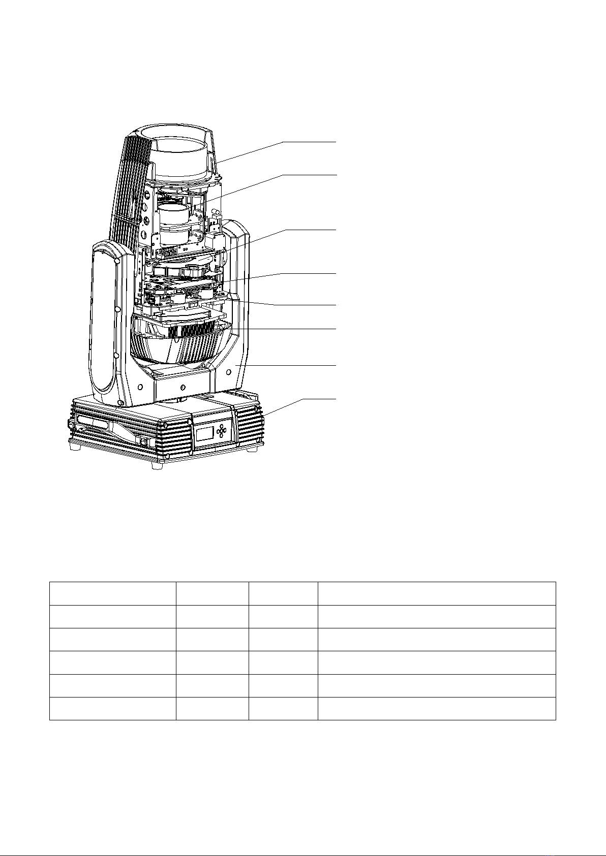
2.2 Fixture overview ...................................................................................................................................................... 4
2.3 Accessories .............................................................................................................................................................. 4
3. Packing and shipping.................................................................................................................................................. 5
3.1 Protection lock ......................................................................................................................................................... 5
3.2 Unpacking................................................................................................................................................................5
3.3 Packing after use ......................................................................................................................................................5
4. Installation ....................................................................................................................................................................6
4.1 Clamps installation.................................................................................................................................................. 6
4.2 Device installation ................................................................................................................................................... 6
5. Power / Control connection ...................................................................................................................................... 7
5.1 Power connection.....................................................................................................................................................7
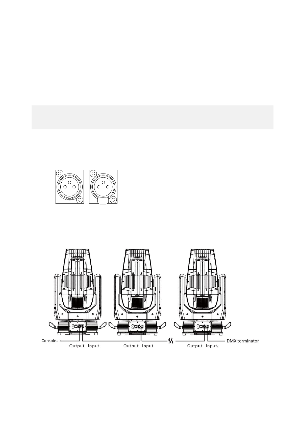
5.2 Control connection...................................................................................................................................................7
5.3 Testing ......................................................................................................................................................................7
6. Control panel ............................................................................................................................................................... 8
6.1 Panel instruction ...................................................................................................................................................... 8
7. Technical specification ................................................................................................................................................ 9
8. Gobos and colors. .......................................................................................................................................................12
8.1 Gobo specification .................................................................................................................................................12
8.2 Gobos..................................................................................................................................................................... 12
8.3 Colors.....................................................................................................................................................................13
9. Menu structure .......................................................................................................................................................... 14
10. DMX protocol .......................................................................................................................................................... 17
11. System wiring diagram ........................................................................................................................................... 33
12. Maintenance and Troubleshooting........................................................................................................................ 34
12.1 Cleaning and maintenance ................................................................................................................................... 34
12.2 Troubleshooting ................................................................................................................................................... 35

1
1. Safety instructions
Before using the fixture, read the latest version of the product user manual, paying particular attention to
the safety instructions. Please check www.gtd-lighting.com for the latest revision/update of the user manual.
m
ta
tc
The manufacture of this fixture, are not responsible for damages, resulting from misuse of this
fixture, due to the disregard of the information printed in this user manual.
DANGER!
Hazardous voltage. Risk of lethal or severe electric shock
WARNING!
Wear protective eyewear. Never look directly into the light source.
WARNING!
Burn hazard. Hot surface. Do not touch.
Only to direct mounting on non-combustible surfaces.
Minimum distance to lighted objects.
Replace all cracked glass shields.
Maximum ambient temperature.
Maximum temp of the external surface.

2
General guidelines
This product has a protection rating of IP66.
Never open this fixture while in use.
The fixture should be kept clean. DO NOT operate the fixture in extreme heat or dusty environments.
Avoid contact with chemical liquid.
Minimum distance to lighted objects must be 16.4feet (5m).
Maximum temp of the external surface 194˚F (90˚C).
Maximum ambient temperature 113˚F (45˚C).
Minimum distance of inflammable materials from the surface 1.6 feet (0.5m).
Lamp should be changed if damaged or distorted in shape due to extreme heat.
Cover, prism or OLED Menu Function Display with visible damages such as cracks or scratches must be
replaced to ensure performance of the fixture.
Disconnect the fixture from power before changing any parts or accessories.
Basic insulation should be maintained between the controllable device and the product power supply.
Make sure that the installation area can hold a minimum point load of 10 times the weight of all installed
fixtures, clamps, cables, auxiliary equipment, etc. Check that the cover, clamps and locks are undamaged.
Certified safety cables must always be used when installing the fixture.
The fixture is only intended for installation, operation and maintenance by qualified professional.
Instructions stated in the manual must be complied.
The fixture must be kept in a well-ventilated place at least 50 cm away from any wall surface. Check if
the fans or ventilation openings are unblocked.
Broken or damaged cables and light source can only be fixed or changed by certified technicians, certified
local distributors or the manufacturer to ensure operational safety.
Do not stick filters or other materials onto the lens. Do not modify the fixture or install other than GTD
manufactured parts.
For questions regarding safety operation, please contact our technical personnel or call the service hotline
+8620 61808296.

3
2. Production instructions
2.1 Dimension
556
(21.9")
(15.3")
(33.7")
(18.1")
(24")
(5.5")
(19.9")
(26.1")
142
664
610
506
458
389
857
270°
270°
270°

4
2.2 Fixture overview
调焦放大组件
固定镜头组件
花样架组件
CMY组件
散热组件
水平垂直扫描架
底箱组件
切割组件
2.3 Accessories
Item
Qty
Unit
Remark
User Manual
1
Pc
--
Clamps
2
Set
02A+21A 42-52mm Load weight 200KG
Safety cable
2
Pc
Φ5*60cm 7*19 pc with hook Material:Steel
3-pins signal line
1
Pc
Power cable
1
Pc
Head module
Prism module
Cutting module
Framing blade system
CMY
Heat module
Pan-tilt frame
Base module

5
3. Packing and shipping
3.1 Protection lock
Pan and tilt locks are equipped to ensure safe transportation.
PAN: 4 lock positions are located evenly on the Pan.
TILT: 7 lock positions are located on left and right side of the Tilt with the third one in the center.
Tilt lock
3.2 Unpacking
Notes
All products are quality controlled and checked for any faults before they are dispatched to customers. If the fixture
is damaged during delivery, the customer must notify the shipper and manufacturer to file a damage insurance
claim. Photographic evidence of the damage must be provided.
Flight-Case:
Open the cover of the flight-case and remove the plastic packing bags. Hold the handles of the fixture
firmly and take it out carefully.
Cardboard box:Open the box and take out the whole set of packaging foam which contains both the fixture and
its accessories. Remove the foam from the top, put away the accessories, and then take out the fixture wrapped in
the plastic bag.
Notes
Check if the pan and tilt are unlocked before connecting the fixture to power.
3.3 Packing after use
1. Switch off the fixture and wait for at least 5 minutes before disconnecting it from AC power. Cool down the
fixture for at least 15 minutes before packing.
2. Lock pan and tilt.
3. Flight case: Wrap the fixture in plastic bags. Hold it by the handles, and then carefully place it inside the flight
case along with all the accessories. Close the cover. Only 3 layers are allowed when piling up the flight cases.
Do not upside down.
4. Cardboard box: Wrap the fixture in plastic bags. Put it in the packaging foam along with all the accessories.
Place the other set of packaging foam on top then carefully put it inside the cardboard box.
Pan lock

6
4. Installation
4.1 Clamps installation
The fixture can be placed on the stage or mounted on the truss facing any direction. Attach the clamps to the
mounting position on the base of the fixture.
Warning:
Use two clamps when mounting the fixture. Turn the screws attached to each clamp a 1/4 turn clockwise
to lock. Always remember to use the safety cable which goes through the mounting hole on the base. Do not attach
the safety cable on the handle.
4.2 Device installation
1. Make sure there is no damage on the clamps or safety cables before installation.
2. The clamp is mounted on the chassis of the fixture. Horizontally insert the clamp into the mounting holes of the
chassis. Fasten the clamp tightly by a 1/4 turn clockwise. Fix another clamp in the same way.
3. Check if pan and tilt are unlocked before connecting the unit to AC power.
680(26.77")200(7.87")
968(38.11")

7
5. Power/ Control connection
5.1 Power connection
Connection method:
L (Live) Brown wire
E (Earth) Yellow / Green bi-color wire
N (Neutral) Blue wire
The voltage and frequency of the power source must be in compliance with the ones marked on the fixture. It
is strongly recommended that each fixture are to be connected to the power source separately so that they
can be switched on / off individually.
5.2 Control connection
The fixture has 3-pin XLR connectors for DMX data input and output as shown below. Connection between the
console and fixture, and between fixtures must be made with 2 core screened DMX signal cable. Maximum
connecting distance of signal cable is 150 meters. Additional DMX512 signal-amplifier is recommended for longer
distance .
Connect the Console’s DMX OUTPUT to the first fixture’s DMX INPUT, then the first fixture’s DMX OUTPUT
to the second fixture’s DMX INPUT and so on. It is recommended not to connect more than 32 units on a single
DMX universe. On the last fixture‘s output connect a DMX terminator. (The terminator is a 3-pin XLR connector
with a 1/4W and 120Ω resistor between the pin 2 and pin 3) as shown below:
5.3 Testing
Connect the fixture to AC power. Check if the lamp is on and the fixture is independently controllable before
putting into operation.
12
3
12
3
DMX 512
1:Ground
2:—
3:+
15
324
15
324
DMX 512
1:Ground
2:—
4:Reserved
5:Reserved
3:+

8
6. Control panel
6.1 Panel instruction
GTD-F10 II PROFILE
5
m
The control panel features touch-sensitive buttons and OLED digital display for quick and easy setup of
address code and functions menu.
Press the left key to enter the menu, press again to exit the menu, press the up and down keys to select the
menu setting item, and press the right key to confirm the setting item. Press the up and down keys to adjust the
value of the setting item, then press the right key to confirm, and press the left key to exit the menu setting
item successively until exiting the menu.
Press up and down to set the address, left to exit, right to confirm.
Middle key (reserved).
Key Panel Indicator Diagram:
Upper
Left Right
Middle
Lower

9
7. Technical specification
Optical
Light source: LED 1000W
Expected average lifetime: 20000 h
Color temperature correction: 6500K
Total luminous flux: 40000Lm
Color rendering index: ≥70Ra
Zoom: 5° -50°
Spot uniformity:≥80%
Focus: multi-point focus, focus from 5 meters to infinity tracking
Prism: 1-facet prism,CW/CCW rotation, variable speed
Frost: 1-independent frost effect
Gobo
Rotating gobo wheel: 6 interchangeable gobos, CW/CCW rotation, variable speed
Fixed gobo wheel: 7 gobos + open,CW/CCW rotation, variable speed
Gobo outside diameter: 27mm
Max. Image diameter: 22mm
Max. Thickness: 3.5mm
Gobo material: Glass
Color
CTO: 6500K-2700K
C、M、Y: linear infinity color mixing
Color wheel: 6 colors + open, split color, CW/C CW rotation, “Rainbow effect” in both directions
Electrical
Power input, nominal: AC 100-240V 50/60Hz
Max. Power consumption: 1170W, max current: 11.74A, PF: ≧0.99
Power supply unit: Wide Voltage switching power supply
Main fuse: 250V/15A
Power input: NEUTRIK socket (input/output)
DMX data input/output: Chassis 3-pin XLR waterproof socket
Control and programming
Control channels (DMX): 36/33/52
Protocol: DMX-512 RDM
Display: OLED
Physical / Installation
Weight: 55Kg (121.25lbs.)

10
IP rating: IP66
Material: Aluminum, steel, plastic, iron, copper
Mounting points: Four quarter-turn locking points + attachment points for safety wire
Dynamic effects
Pan/Tilt movement: 540˚/270˚
Iris: Motorized adjustable iris, wide range of variable pulse effects
Strobe: 1-25Hz, synchronized, pulse effects
Dimmer: 0-100%, mechanical dimming
Thermal
Startup range: -13˚F to 113˚F (-25˚C to 45˚C)
Storage range: -40˚F to 140˚F (-40˚C to 60˚C)
Cooling: Active fan
Certification and Safety
EMC: EN 55103-1:2009, EN 55103-2:2009, EN 61000-3-2:2006+A2:2009, EN 61000-3-3:2013,
GB/T 17743-2007, GB 17625.1-2012
Safety: EN 60598-2-17:1989/A2:1991, GB 7000.1-2015, GB 7000.217-2008
Photometric
∅
5°
50°
50°
5°
25m
20m
15m
10m
5m
0
5m
10m
15m
20m
25m
32300128000 14500 8050
4530
0 5
0.48 ∅0.96 ∅1.44 ∅1.92
∅4.87 ∅9.76 ∅14.92 ∅19.81
10 15 20
1600 710 419
5°
50°
Distance(m)
Beam distance
Beam distance

11
Other features
Enhanced stability of the fixture due to the wide input voltage AC/DC switching power supply which both
reduces the impact of power and voltage fluctuations, and removes the restriction of voltage and frequency
variations in different countries.
Automatic energy saving: when the shutter or CMY is closed, power consumption will be reduced
automatically with the photoelectric tracking induction technology.
Sleep mode: uses the most advanced technology to remotely activate sleep mode. When the fixture is
disconnected from signal, the sleep mode is enabled automatically to make it more stable and safer. Sleep time
can be customized.
Power setting: built-in continuous rechargeable battery, allowing setting functional data via OLED interface
without power connection.
Communication: DMX wired transmission, RDM two way control technology, upgrade software easily with
DMX cable.
Dissipate heat: With wind direction drainage and temperature intelligent momitoring technology, it can
automatically adjust the heat dissipation system and effectively control the bulb temperature according to the
start, use, close and other states of the lamp, and the temperature of different positions of the lamp.

12
8. Gobos and colors
8.1 Gobo specification
All patterns are made onto the metal gobos, and can be customized according to user’s requirement.
The customized size is as below:
Gobo material
Outer dimension
Effective dimension
Thickness
Glass gobo
Φ27mm
Φ22mm
3.5mm
Gobo material: Glass
8.2 Gobos
One rotating gobo wheel: 6 interchangeable gobos + open, indexing, CW/CCW rotation, variable speed
One fixed gobo wheel: 7 gobos + open, CW/CCW rotation, variable speed
Rotating gobo wheel Fixed gobo wheel
Effect wheel
7

13
8.3 Colors
One color wheel: 6 colors + open, split color, CW/CCW rotation, “Rainbow effect” in both directions
Cutting effect
0: Open
1: Red
2: Orange
3: Green
4: Yellow
5: Blue
6:CRI
0
1
2
3
4
5
6
CYAN
YELLOW
MAGENTA
CTO

14
9.Menu structure
Level 1
Level 2
Level 3
Level 4
Info
Run
setting
Address Setting
Value Display
Auto-Program
Address: 001~ XXX
Pan ……,All,Off
Master /Slave
Setting the DMX address
Display the channel value
Run auto program in master
or slave
Device
Info
Time Info
Since power on
Total Time
Last Time
Lamp On Time
Lamp Off Time
Last Time Code
Clear Last Time
Lamp Time Code
Clear Lamp Time
XXXXXX Hour
XXXXXX Hour
XXXXXX Hour
XXXXXX Hour
XXXXXX Minute
Password: XXX(XX)
Yes/No
Password: XXX(XXX)
Yes/No
Since power on time
Product total run time
Last product run time
Lamp on time
Lamp close time
Clear last time password
Clear last time
Clear lamp time password
Clear lamp time
Temperature
Temperature1/2/3
XXX ’C/’F
Body temperature
Fans’ Err
Ok/Err/No
Show fans’ status
Err Inf
No/...
Show this device’s status
Software Version
X.X
The software version
System
Setting
Status Setting
Console Set Addr
No Signal Status
Pan Reverse
Tilt Reverse
Pan Scan Degree
Scan Feedback
Scan Speed
Standby Time
Enable/Disable
Off/Hold/Auto/Music
Enable/Disable
Enable/Disable
360/540
Enable/Disable
Quick/Middle/Low/Slow
Disable/1~20~99 Min
Address can be changed by
console
The status while no signal
Pan Reverse
Tilt Reverse
Pan Scan Degree
Scan Feedback
Change the scan speed
Standby time
Fan Speed
Smart Control
High Speed
Low Speed
Auto fans speed
Fans high speed
Fans low speed
Display Setting
Backlight Time
Key Lock
Lightness
Language
1~80 Min/Disable
Enable/Disable
15~100% 80%
Chinese/English
Backlight off time
Press <menu> 3s to unlock
Back lightness of screen
Change the language

15
Screen auto
off/on/auto
Screen change Setting
Temperature Unit
Celsius
Fahrenheit
Temperature unit
Value Default
Pan……
Pan =XXX
The default value
Wireless Dev
Wireless Off
Wireless On
Wireless Trans.
Wireless Reset
Wireless off
Wireless on
Wireless transfer DMX data
to another
Wireless reset
Restore Default
Yes/No
Restore to default value
Product Select
- Password-
GTD xxx xxx xxx
Product Name Select
Reset
System Reset
Scan Reset
ColorReset
Gobo Reset
Other Reset
System reset
Pan and tilt motor reset
Color motor reset
All gobo motor reset
All other motor reset
Channel
Adjust
Test Mode
Pan……
Every channel test
Manual Mode
Pan
:
Pan =XXX
:
Manual control
Adjust Mode
Input Password
Pan
:
Password=XXX(XX)
Pan=XXX
:
The password of adjust
mode
Fixed all begin position
Focus Mode
Input Password
Pan
:
Password=XXX(XX)
Pan=XXX
:
The password of adjust
mode
Fixed all begin position
Channel
Setting
Channel Mode
Standard Mode
Simplified Mode
Extended Mode
Custom Mode 1
Custom Mode 2
Custom Mode 3
Standard channel mode
Simplified channel mode
Extended channel mode
Custom channel mode 1
Custom channel mode 2
Custom channel mode 3
Set Custom Mode1
Set Custom Mode2
Set Custom Mode3
Max Channel
Pan
:
Channel = XX
Pan = CH01
:
Change the channel order
Program
Select Prog.
Program Unit 1
Program 1 ~10
Choose build-in program for

16
Edit
Program Unit 2
Program Unit 3
Program 1 ~ 10
Program 1 ~ 10
slave 1
Choose build-in program for
slave 2
Choose build-in program for
slave 3
Program Edit
Auto-Program1
:
Auto-Program10
Run
Step 1=Scene xxx
Step 8=Scene xxx
Choose the scene for
program 1
:
Choose the scene for
program 10
Scene Edit
Scene Edit:001-250
Pan,……Pan=xxx
Scene Time=xxx
Input By Console
Edit the channel DMX
Edit the scene time
Get scene DMX form
console
Record Scene
Scene XX->XX
Record scene form console
Note:Settings hightlighted in light grey are default values.

17
10. DMX Protocol
Standard
DMX
mode
Name
DMX value
DMX percentage
Function
Defaul
t DMX
Value
Standard
(36ch)
1
Strobe/
Shutter
0
31
0.0%
12.2%
Closed
0(0%)
32
63
12.5%
24.7%
Open
64
127
25.1%
49.8%
Synchronous strobe from slow to
fast
128
159
50.2%
62.4%
Open
160
223
62.7%
87.5%
Random strobe from slow to fast
224
255
87.8%
100.0%
Open
2
Intensity
0
255
0.0%
100.0%
No light Full light
0(0%)
3
Cyan
0
255
0.0%
100.0%
White Full cyan
0(0%)
4
Magenta
0
255
0.0%
100.0%
White Full magenta
0(0%)
5
Yellow
0
255
0.0%
100.0%
White Full yellow
0(0%)
6
CMY
color
macro
0
15
0.0%
5.9%
CMY color macro off
0(0%)
16
135
6.3%
52.9%
CMY synchronous color from slow
to fast
136
255
53.3%
100.0%
CMY random color from slow to fast
7
CTO
0
255
0.0%
100.0%
White Full cyan
0(0%)
8
Color
wheel
0
19
0.0%
7.5%
Open
0(0%)
20
37
7.8%
14.5%
Color 1
38
55
14.9%
21.6%
Color 2
56
73
22.0%
28.6%
Color 3
74
91
29.0%
35.7%
Color 4
92
109
36.1%
42.7%
Color 5
110
127
43.1%
49.8%
Color 6
128
187
50.2%
73.3%
Color continous rotation CW from
slow to fast
Table of contents
Other GTD Lighting Equipment manuals

GTD
GTD LM1000 N BSWP User manual

GTD
GTD GTD-LZ354P User manual

GTD
GTD GTD-L336P User manual

GTD
GTD 440P II BSW User manual

GTD
GTD LMZ1537 User manual

GTD
GTD GTD-LP200 User manual

GTD
GTD GTD-470NBSW User manual

GTD
GTD GTD-371C II BSW User manual

GTD
GTD GTD-LM660 II Profile User manual

GTD
GTD GTD-L1508P User manual

GTD
GTD GTD-L1254P User manual

GTD
GTD GTD-L2016P User manual

GTD
GTD GTD-F4019 WASH User manual

GTD
GTD GTD-LM1000 II BSWP User manual

GTD
GTD GTD-L2008P User manual

GTD
GTD GTD-1400 II PROFILE User manual

GTD
GTD TUNGDOU TD-L354P User manual

GTD
GTD GTD-330 N BSW User manual

GTD
GTD GTD-L372P User manual

GTD
GTD GTD-F5 User manual