GTD GTD-L1254P User manual

LED PAR LIGHT
GTD-L1254P
User’s Manual
Guangzhou GTD Lighting Technology Co., Ltd.
Tel: +86-20-61808296
Fax: +86-20-61812282
http://www.gtd-lighting.com

GTD-L1254P User Manual
1
© 2017 GTD all rights reserved. Information, specifications, diagrams, images, and instructions herein are subject to
change without notice. GTD logo and identifying product names and numbers herein are trademarks of GTD. Copyright
protection claimed includes all forms and matters of copyrightable materials and information now allowed by statutory or
judicial law or hereinafter granted. Product names used in this document may be trademarks or registered trademarks of
their respective companies and are hereby acknowledged. All non-GTD brands and product names are trademarks or
registered trademarks of their respective companies.
GTD and all affiliated companies hereby disclaim any and all liabilities for property, equipment, building, and electrical
damages, injuries to any persons, and direct or indirect economic loss associated with the use or reliance of any
information contained within this document, and/or as a result of the improper, unsafe, insufficient and negligent
assembly, installation, rigging, and operation of this product.
Guangzhou GTD Lighting Technology Co., Ltd. | 27 Fu Yuan Yi Road, Guangzhou 510805, P.R.China
+86-20-61808296 | +86-20-61812282 fax | www.gtd-lighting.com | contact@gtd-china.com

GTD-L1254P User Manual
2
Contents
Safety instructions...................................................................................................................................................................... 3
General guidelines...................................................................................................................................................................... 4
Packing and shipping .................................................................................................................................................................. 5
Unpacking ....................................................................................................................................................................................... 5
Packing after use............................................................................................................................................................................. 5
Accessories................................................................................................................................................................................. 5
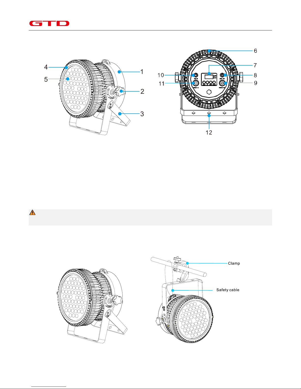
Product introduction .................................................................................................................................................................. 6
Installation ................................................................................................................................................................................. 6
Clamps installation ......................................................................................................................................................................... 6
Device installation .......................................................................................................................................................................... 6
Power / Control connection ....................................................................................................................................................... 7
Power connection........................................................................................................................................................................... 7
Control connection ......................................................................................................................................................................... 7
Testing ............................................................................................................................................................................................ 8
Control panel.............................................................................................................................................................................. 8
Menu structure .......................................................................................................................................................................... 9
DMX protocol........................................................................................................................................................................... 10
Technical specification ............................................................................................................................................................. 12
Cleaning and maintenance ....................................................................................................................................................... 14
Troubleshooting ....................................................................................................................................................................... 15
System wiring diagram ............................................................................................................................................................. 16
Spare parts list ......................................................................................................................................................................... 16
Appendix 1 ............................................................................................................................................................................... 16

GTD-L1254P User Manual
3
Safety instructions
WARNING!
Before using the fixture, read the latest version of the product user manual, paying particular attention
to the safety instructions. Please check www.gtd-lighting.com for the latest revision/update of the user
manual. The manufacture of this fixture, are not responsible for damages, resulting from misuse of this
fixture, due to the disregard of the information printed in this user manual.
DANGER!
Hazardous voltage. Risk of lethal or severe electric shock.
WARNING!
Burn hazard. Hot surface. Do not touch.
WARNING!
Fire hazard.
It’s essential that the fixture is properly grounded. Only qualified personnel should perform electrical
connections.
WARNING!
Wear protective eyewear. Never look directly into the light source.
Only qualified and certified personnel should perform installation of this fixture and only the original rigging parts
(brackets) included with this fixture should be used for installation.
Before applying power to the fixture, check that the source voltage matches the fixture's requirement. Every fixture
must be earthed (grounded) and installed in accordance with local electricity regulations. Do not connect it to a
dimmer system.
Never look directly into the light source of this fixture to prevent risk of injury to your retina, which may induce
blindness.

GTD-L1254P User Manual
4
General guidelines
Never open this fixture while in use.
The fixture should be kept clean. DO NOT operate the fixture in extreme heat or dusty environments. Avoid contact
with chemical liquid.
IP rating: IP65. It should be kept away from the high ambient or dusty environments. Don’t let the fixture contact
with chemical liquids.
Minimum distance to lighted objects must be 3.28feet (1m).
Maximum temp of the external surface 158˚F (70˚C).
Maximum ambient temperature 113˚F (45˚C).
Minimum distance of inflammable materials from the surface 1.6 feet (0.5m).
The light source of the fixture should be changed by the manufacture or its service agent or certified technicians.
WARNING! Risk of electric shock.
The basic insulation should be kept between the controllable device and the power supply.
Cover, lens or Menu Function Display with visible damages such as cracks or scratches must be replaced to ensure
performance of the fixture.
Disconnect the fixture from power before changing any parts or accessories.
Make sure that the installation area can hold a minimum point load of 10 times the weight of all installed fixtures,
clamps, cables, auxiliary equipment, etc. Check that the cover, clamps and locks are undamaged. Certified safety
cables must always be used when installing the fixture.
The fixture is only intended for installation, operation and maintenance by qualified professional. Instructions
stated in the manual must be complied.
The fixture must be kept in a well-ventilated place at least 50 cm away from any wall surface. Check if the fans or
ventilation openings are unblocked.
Broken or damaged cables can only be fixed or changed by certified technicians, certified local distributors or the
manufacturer to ensure operational safety.
Do not stick filters or other materials onto the lens. Do not modify the fixture or install other than GTD
manufactured parts.
For questions regarding safety operation, please contact our technical personnel or call the service hotline +8620
61808296.

GTD-L1254P User Manual
5
Packing and shipping
Unpacking
Notes
All products are quality controlled and checked for any faults before they are dispatched to customers. If the fixture is
damaged during delivery, the customer must notify the shipper and manufacturer to file a damage insurance claim.
Photographic evidence of the damage must be provided.
Flight-Case
Open the cover of the flight-case and remove the plastic packing bags. Hold the handles of the fixture firmly and take it
out carefully.
Cardboard box
Open the box and take out the whole set of packaging foam which contains both the fixture and its accessories. Remove
the foam from the top, put away the accessories, and then take out the fixture wrapped in the plastic bag.
Packing after use
1. Switch off the fixture and wait for at least 5 minutes before disconnecting it from AC power. Cool down the fixture for
at least 15 minutes before packing.
2. Flight case: Wrap the fixture in plastic bags. Hold it by the handles, and then carefully place it inside the flight case
along with all the accessories. Close the cover. Do not upside down.
Cardboard box: Wrap the fixture in plastic bags. Put it in the packaging foam along with all the accessories. Place the
other set of packaging foam on top then carefully put it inside the cardboard box.
Accessories
Item
Qty
Unit
Notes
User Manual
1
pc
-
Clamps
1
set
Ø42-52mm, Max. 200 kg
Power Cord [water-proof]
1
pc
0.5*2.5mm2 , IP67
Notes
Accessories are subject to change without any prior written notice.

GTD-L1254P User Manual
6
Product introduction
1 Cast-aluminum back cover
2 Manually-adjustable screw
3 Arm bracket
4 Head cover
5 LED lens
6 Safety cable mounting position
7 Display screen
8 DMX output
9 Power output
10 DMX input
11 Power input
12 Clamp mounting hole
Installation
Clamps installation
The fixture can be placed on the stage or mounted on the truss facing any direction. The fast-lock clamp gives a quick and
easy lock on the truss.
Warning
Use one clamp when mounting the fixture. Fasten the screw properly and connect a safety cable to fixture.
Device installation
1. Make sure there is no damage on the clamps or safety cables before installation.
2. The clamp is mounted on the bracket of the fixture. Horizontally insert the clamp into the mounting holes of the
bracket. Fasten the clamp tightly.
Placed on the floor Hanging on the truss

GTD-L1254P User Manual
7
Power/ Control connection
Power connection
Connection method:
L (Live) Brown wire
E (Earth) Yellow / Green bi-color wire
N (Neutral) Blue wire
The voltage and frequency of the power source must be in compliance with the ones marked on the fixture. Please
apply series connection when many sets of fixtures are connected to the power source to avoid heavy load to the
power source. When the voltage is 220V, maximum 9 sets of fixtures could be allowed in each series connection.
Another series connection should be set up for extra fixtures.
Notes
It is essential that each fixture is correctly grounded and the electrical installation conforms to all relevant Standards /
Codes of Practice for Safe Electrical Work.
Control connection
The fixture has 5-pin XLR connectors for DMX data input and output (3-pin optional) as shown below. Connection between
the console and fixture, and between fixtures must be made with 2 core screened DMX signal cable. Maximum connecting
distance of signal cable is 150 meters. Additional DMX512 signal-amplifier are recommended for longer distance.
Connect the Console’s DMX OUTPUT to the first fixture’s DMX INPUT, then the first fixture’s DMX OUTPUT to the second
fixture’s DMX INPUT and so on. It is recommended not to connect more than 32 units on a single DMX universe. On the
last fixture‘s output connect a DMX terminator. (The terminator is a XLR connector with a ¼ W and 120Ω resistor between
the pin 2 and pin 3) as shown below:

GTD-L1254P User Manual
8
Testing
Connect the fixture to AC power. Check if the LED lamp is on and the fixture is independently controllable before putting
into operation.
Control panel
The control panel with buttons and digital display can access the function menu and configure the fixture easily.
Press MENU to check or modify the functions of the fixture; Press UP or DOWN to view or select the function
menu.
Press ENTER to choose a function and enter into corresponding sub menu. Each menu represents a specific
function of the fixture.
Press ENTER to select the specific function and save the changes or enter into the submenu, then press UP or
DOWN to change the value of the selected function (increase or decrease).
Press MENU to return to the previous menu or exit.
LED indicators:
Power on: RED power LED indicator on
Signal on: Green DMX indicator on
No Signal: Green DMX indicator off

GTD-L1254P User Manual
9
Menu structure
L1254P - Menu Structure
Revision: A
Valid from firmware version: 1.0
Level 1
Level 2
Level 3
Level 4
Info
Addr
AXXX A001
Setting the DMX address
Play
RUN
MSTR/ALON
Running build-in program as the master or the slave
AUDI
MSTR/ALON
Receiving soundsignal as the master or the slave
AUTO
Clos/Hold/Auto/Audi
Setting the status when no DMX signal received
CH
CH2
Standard channel mode
CH1
Basic channel mode
MIC
M-XX M-72
Adjusting the sensitivity of Microphone
DISP
VALU
D–XX D-00 (DXXX)
Display the channel value
DON
ON/OFF
Turn on or off the Backlight time function
EDDY
ON/OFF
Inverted Display
SET
RDMX
ON/OFF
Allow the console to change the Address
DEFA
ON/OFF
Factory reset
FANS
AUTO/HIGH/LOW
Setting the Fans’ status
Save
OFF/1-99M 15M
Close the LED light when no signal
Ver
V1.0~V9.9
Software version
STAT
R-xx
xxx
Manual control
Edit
SEPR
AUTO
IP01~IP10
Selecting the program that want to edit
STEP
S–01 ~S–48
Setting the steppes of program
SCXX
C–01~C–XX
XXX(0~255)
Editing program by manual
TIME
T XXX(001~999)
Running time
CEDT
ON/OFF
Receiving build-in program from console or not
REC.
RE.XX
Recording senses automatically
RUN
ON/OFF
Program test
SDMD
MOD0~MOD5
MOD1
Dimmer mode select
Notes
Settings highlighted in light grey are default values.

GTD-L1254P User Manual
10
DMX protocol
L1254P - DMX Protocol
Revision: A
Valid from firmware version: 1.0
DMX mode
Name
DMX value
DMX percentage
Function
Default
DMX
Value
Standard
(15ch)
Basic
(8ch)
1
1
Strobe/Shutter
0
31
0.0%
12.2%
Closed
0(0%)
32
63
12.5%
24.7%
Open
64
127
25.1%
49.8%
Synchronous strobe from slow to fast
128
159
50.2%
62.4%
Open
160
223
62.7%
87.5%
Random strobe from slow to fast
224
255
87.8%
100.0%
Open
2
2
Intensity
0
255
0.0%
100.0%
No light →Full light
0(0%)
3
0
65535
0.0%
100.0%
Intensity fade, fine (LSB)
4
3
Red
0
255
0.0%
100.0%
No light →Full light
0(0%)
5
0
65535
0.0%
100.0%
Intensity fade, fine (LSB)
6
4
Green
0
255
0.0%
100.0%
No light →Full light
0(0%)
7
0
65535
0.0%
100.0%
Intensity fade, fine (LSB)
8
5
Blue
0
255
0.0%
100.0%
No light →Full light
0(0%)
9
0
65535
0.0%
100.0%
Intensity fade, fine (LSB)
10
6
White
0
255
0.0%
100.0%
No light →Full light
0(0%)
11
0
65535
0.0%
100.0%
Intensity fade, fine (LSB)
12
7
Rainbow
Function
0
9
0.0%
3.5%
No function
0(0%)
10
39
3.9%
15.3%
Rainbow scene 1
40
71
15.7%
27.8%
Rainbow scene 2
72
103
28.2%
40.4%
Rainbow scene 3
104
135
40.8%
52.9%
Rainbow scene 4
136
167
53.3%
65.5%
Rainbow scene 5
168
199
65.9%
78.0%
Rainbow scene 6
200
231
78.4%
90.6%
Rainbow scene 7
232
255
91.0%
100.0%
Rainbow flow from slow to fast

GTD-L1254P User Manual
11
DMX mode
Name
DMX value
DMX percentage
Function
Default
DMX
Value
Standard
(15ch)
Basic
(8ch)
13
8
Color
temperature
0
24
0.0%
9.4%
No function
0(0%)
25
35
9.8%
13.7%
3200K
36
46
14.1%
18.0%
3400K
47
57
18.4%
22.4%
3600K
58
68
22.7%
26.7%
3800K
69
79
27.1%
31.0%
4000K
80
90
31.4%
35.3%
4200K
91
101
35.7%
39.6%
4400K
102
112
40.0%
43.9%
4600K
113
123
44.3%
48.2%
4800K
124
134
48.6%
52.5%
5000K
135
145
52.9%
56.9%
5200K
146
156
57.3%
61.2%
5400K
157
167
61.6%
65.5%
5600K
168
178
65.9%
69.8%
5800K
179
189
70.2%
74.1%
6000K
190
200
74.5%
78.4%
6200K
201
211
78.8%
82.7%
6400K
212
222
83.1%
87.1%
6600K
223
233
87.5%
91.4%
6800K
234
244
91.8%
95.7%
7000K
245
255
96.1%
100.0%
7200K
14
Dimmer mode
0
5
0.0%
2.0%
M0:600Hz,Gama1.5,Smooth
0(0%)
6
11
2.4%
4.3%
M1:600Hz,Gama1.5,Snap
12
17
4.7%
6.7%
M2:1200Hz,Gama1.5,Smooth
18
23
7.1%
9.0%
M3:1200Hz,Gama1.5,Snap
24
29
9.4%
11.4%
M4:600Hz,Gama2.0,Smooth
30
35
11.8%
13.7%
M5:600Hz,Gama2.0,Snap
36
255
14.1%
100.0%
Reserved
15
Special controls
0
239
0.0%
93.7%
No function
0(0%)
240
249
94.1%
97.6%
Dimmer mode set
250
255
98.0%
100.0%
No function

GTD-L1254P User Manual
12
Technical specification
Optical
Light source: LED 12W (RGBW 4 in1), quantity: 54pcs
Expected average lifetime: 50000 hours
Beam angle (50% peak angle): 19°(standard), 27°/ 43°(optional)
Beam angle (10% peak angle): 25°(standard), 45°/ 60°(optional)
RGBW liner color mixing, each ring of LEDs individually controllable
Photometric
Total Output (Lumen): 6926 lumens
Color temperature: 3200K-7200K linear regulation
Mixing distance: 0.3m
Electrical
Power input, nominal: AC 200-240V, 50/60Hz
Max. Power consumption: 174W, max current: 1.38A, PF: 0.6
Power supply unit: Auto-ranging electronic SMPS
Control and programming
Control channels (DMX): 15/8
Protocol: DMX-512
Display: 4 x 8 segment display
16-bit control: Dimmer
Physical / Installation
Weight: 7 .5kg (17 lbs.)
IP rating: IP65
Material: Aluminum, steel, plastic
Dynamic effects
Pan/Tilt movement: Manually adjustable
Strobe: 1-25Hz, synchronized, pulse effects
Dimmer: 0-100%, 16-bit, electronic linear dimming (600Hz /1200Hz smooth or snap dimmer mode optional)
Thermal
Operating range: 14˚F to 113˚F (-10˚C to +45˚C)
Startup range: 5˚F to 113˚F (-15˚C to +45˚C)
Storage range: -40˚F to 140˚F (-40˚C to +60˚C)
Cooling: Passive
Humidity: ≤98%

GTD-L1254P User Manual
13
Connections
AC power: 1m (3.28 ft.) cable with water proof plugs (in/out)
DMX data input/output: 2 x 1m (3.28 ft.) cable with 5-pin Neutrik IP65 XLR plugs (in/out)
Certification and Safety
EMC: EN 55103-1:2009, EN 55103-2:2009, EN 61000-3-2:2006+A2:2009, EN 61000-3-3:2013
Safety: EN 60598-2-17:1989/A2:1991
Photometric
Standard:
Optional:

GTD-L1254P User Manual
14
Cleaning and maintenance
It is required that the fixture should be kept clean and well maintained to ensure its reliability. Its lifespan mainly depends
on the working environment and proper operation. Should you have any questions, please consult a technical engineer of
GTD Lighting.
Notes
Damage resulted from dust, smoke, oil or improper use is not covered by warranty.
Warning
Disconnect the fixture from AC power, and let it cool down for at least 15 minutes before opening the housing. Make sure
to use a soft cloth to clean the optical components, and be careful, as the coating is easily scratched. Do not use any
organic solvent such as alcohol to clean the reflector mirror, dichroic color filters or housing of the fixture.
If the lens is cracked or otherwise damaged, replace it immediately.
If the LED lamp becomes damaged or deformed in any way it must be replaced.
If the light from the LED lamp appears dim, this normally indicates that it is reaching the end of its life span and
should be changed at once. Aged LED lamps run to the extremity of their life might explode.
If fixture does not function, check the fuse on the power socket of the fixture. Replace the fuse of the same
specification if it is blown.
The fixture is equipped with thermal-protection device that will switch off the LED lamp in case of overheating. If
this happens, please check that the fans are not blocked, and clean them if they are dirty. Check whether the fans
are operational. If not, call a qualified technician. Troubleshoot and correct the problem before switching on the
fixture again. Any maintenance work should only be carried out by qualified technicians.

GTD-L1254P User Manual
15
Troubleshooting
Problem
Possible Cause
Suggested Correction
No response
after connected
to A/C power
Power switch not turned on.
Turn on power switch.
Take out the fuse and check if it is blown.
Locate the blown fuse. Remove the broken fuse. Insert a
replacement fuse of the correct amperage.
Abnormal A/C input (A/C power socket,
power cables, luminaire power socket).
Replace AC power socket and power cables, and then adjust power
socket for proper connection.
No DC voltage from switching power
supply.
Check if the switching power supply has DC voltage output. Replace
the switching power supply.
No response or
wrong response
to the
commands of
the control
system
DMX cables disconnected from fixture’s
DATA IN connector.
Connect DMX cable to the fixture’s DATA IN connector.
Open circuit or short circuit fault in the
DMX cables.
Replace DMX cables as required.
Wrong DMX address for the fixture in the
control system.
Ensure the address in “Run setting > Address Setting > Address”of
the fixture is consistent with the address in the control system.
Misuse in “Channel setting > Channel
Mode” of the fixture.
Choose the channel mode in “Channel setting > Channel Mode” of
the fixture as required by the user.
Malfunctioning of DMX cannon input
/output connectors. No input/output
voltage to the main control board of the
fixture.
Troubleshooting the DMX XLR signal plate of the fixture, replace the
main control board of the fixture.
LED lamp off
There is no signal output to the main
control board PWM.
Replace the main control board or repair.
No output to the drive board LED +/ LED-
or drive board over-current, check line
connector if contact bad.
Reconnect the terminal, replace the driver board
Normal end of LED lamp life, bad welding
or poor heat dispersion.
Repair or replace LED light source or replace the whole piece of
aluminum board, remove the cooling system failure.
Decreased
brightness,
uneven pattern
projections
LED lamp aging, check the service time of
LED light source, test LED drive board’s
current.
Replace the LED light source or adjust the drive board’s current.
Reduce LED’s brightness.
Excessive dusts or smudges on the effect
assembly, focus module and objective
lens.
Follow the instructions stated in this user manual to clean the effect
assembly, focus module and objective lens.
Damaged or deformed effect assembly,
focus module or objective lens.
Replace the damaged or deformed components.

GTD-L1254P User Manual
16
System wiring diagram
Spare parts list
Item
P/N
Qty
Notes
LED aluminum substrate
5802010060A
1
LJB0225C
Aluminum substrate 0224B-1
5802030102A
1
LJB0224B
Display board
5809210080A
1
L1254P-101K10 SDI0207B
Switching power supply
1412050057A
1
EDS200-3624 36V/5.13A 24V/0.625A
Appendix 1
LJB0224A
+24V
GND
+24V FG
L
N
POWER E
L
N
J3
+36V
GND
LJB0225A
GND
JF1
JF2
J1
J2
EDS-200 3624
FAN
J3
SDI0207B
GTD-L1254P
LED aluminum substrate
LJB0224A
P2
P3
P1
Driver board
P5
J7 JC1
P2
P3
P1
P5
Driver board
Display board
266mm
(10.5'')
275mm
(10.8'')
198mm
(7.8'')
230mm
(9.1'')

GTD-L1254P User Manual
17
Notes:
P/N: 1502011063A
Time: May 10th, 2017
Table of contents
Other GTD Lighting Equipment manuals

GTD
GTD GTD-F4019 WASH User manual

GTD
GTD GTD-1400 II PROFILE User manual

GTD
GTD GTD-L336P User manual

GTD
GTD 440P II BSW User manual

GTD
GTD GTD-LM660 II Profile User manual

GTD
GTD GTD-L2008P User manual

GTD
GTD GTD-330 N BSW User manual

GTD
GTD GTD-371C II BSW User manual

GTD
GTD GTD-L372P User manual

GTD
GTD GTD-F10 II PROFILE User manual