GUIDANCE MARINE RadaScan View Assembly instructions

Guidance Marine Ltd, 4 Dominus Way, Meridian Business Park, Leicester LE19 1RP, UK www.guidance.eu.com
RadaScan Installer’s Guide
W
A
R
R
A
N
T
Y
S
e
e
o
u
r
s
t
a
n
d
a
r
d
t
e
r
m
s
o
f
s
a
l
e
Q
U
A
L
I
T
Y
A
S
S
U
R
E
D
3
YEAR
featuring RadaScan
Dashboard
Guidance Marine Ltd, 5 Tiber Way, Meridian Business Park, Leicester, LE19 1QP, UK

Guidance Marine Ltd,
5 Tiber Way
Meridian Business Park
Leicester
LE19 1QP
UK
Tel: +44 116 229 2600
Tel (Customer Services): +44 116 229 2665
Web: www.guidance.eu.com/customer-support
RadaScan (Dashboard) Installer’s Guide
Issue Date: 29/03/2017
Document No: 94-0394-4-C
Copyright © Guidance Marine Limited. All Rights Reserved.
Copyright in the whole and every part of this document belongs to Guidance Marine Limited
(the “Owner”) and may not be used, sold, transferred, copied or reproduced in whole or in part
in any manner or form or in or on any media to any person other than in accordance with the
terms of the Owner’s Agreement or otherwise without the prior written consent of the Owner.
“RadaScan”and “Mini RadaScan”are registered trademarks of Guidance Marine Ltd. ”Windows”
is a trademark of Microsoft Corporation. All other brand or product names are trademarks or
registered trademarks of their respective companies or organisations.
Serial No:
Date of Shipment from UK:
Sensor Software Version: Dashboard Software Version:
VYMRADASCAN

Document Number Changes Issue Date
94-0394-4-A First release of RadaScan (Dashboard) Installer’s Guide 23/12/2014
94-0394-4-B New DIN rail assembly, new radome and Series 3 responders 19/11/2015
94-0394-4-C New standard sensor connections diagram 29/03/2017
Document History
3

Introduction
Welcome ................................................................................................................... 6
System Overview....................................................................................................... 7
Important Safety Notes.............................................................................................. 8
Non-ionising Radiation.......................................................................................................8
Risk of Electric Shock ........................................................................................................8
Isolating the Sensor ...........................................................................................................8
Lifting the Sensor...............................................................................................................9
Serial Numbers and Software Versions .................................................................... 10
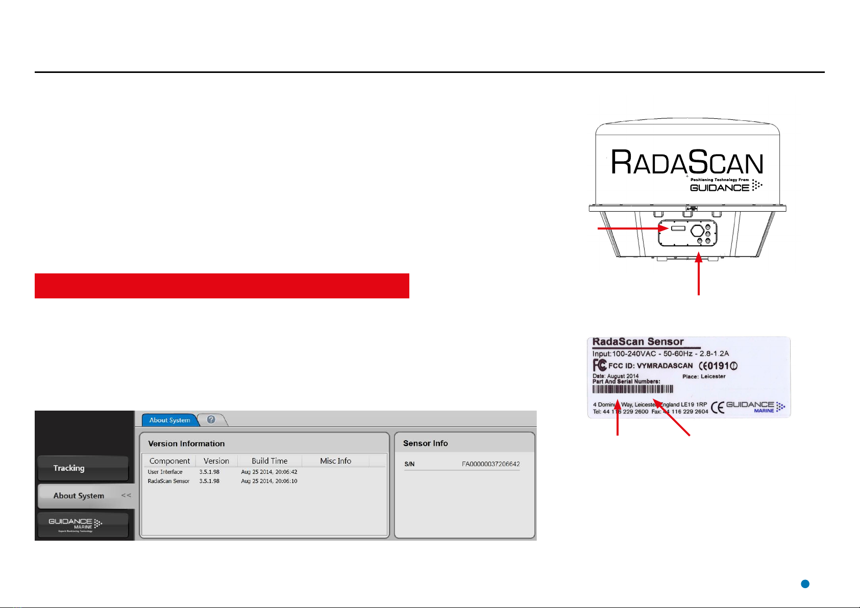
Product Labels ................................................................................................................10
Software Version Information ...........................................................................................10
To Display the About System Pane ..................................................................................10
Installing the Sensor Hardware and Software
Mounting the Sensor ............................................................................................... 12
Avoiding Other Sources of Radiation................................................................................13
Operating Area Astern (e.g. PSV) .....................................................................................14
Operating Area Forward (e.g. Shuttle Tanker) ...................................................................15
Operating Area to Port or Starboard (e.g. Track and Follow).............................................16
Sensor Dimensions.................................................................................................. 17
Mounting Template .................................................................................................. 18
Standard Sensor Connections - Direct..................................................................... 19
Low Temperature Sensor Connections - Direct........................................................ 20
Sensor Connections - Separate Ethernet Connection Box (3 Glands) ...................... 21
Sensor Connections—Separate Ethernet Connection Box (4 Glands)...................... 22
Cable Routing Diagram - Direct Connection ............................................................ 23
Cable Routing Diagram - Separate Connection Box ................................................ 24
Cable Routing Diagrams - Processor and Monitor Options ...................................... 25
Sensor Information Display ...................................................................................... 26
Installing the Sensor Software.................................................................................. 28
Installing the Type 2 Marine Processor
Type 2 Marine Processor Dimensions ...................................................................... 30
Plan view .........................................................................................................................30
Type 2 Marine Processor Connections..................................................................... 31
Installing the Dashboard Software onto a Type 2 Marine Processor ......................... 32
Installing the Dashboard Software onto a Hatteland Panel PC ................................. 33
Changing the Sensor IP Address Setting ................................................................. 34
Conguring the RadaScan Dashboard
Start Up and Shut Down ......................................................................................... 36
Start Up...........................................................................................................................36
Shut Down ......................................................................................................................36
Setting the Date and Time ....................................................................................... 37
Using the On-Screen Keyboard ............................................................................... 38
Entering Service Access Mode ................................................................................ 39
Conguration Settings ............................................................................................. 40
DP Message Format and Feed Behaviour................................................................ 41
Display Options ....................................................................................................... 43
Vessel Parameters ................................................................................................... 44
Bow and Starboard Offsets..............................................................................................45
Bearing Offset..................................................................................................................46
Blanking Zone ......................................................................................................... 47
Installing Responders
Responder Overview ............................................................................................... 49
Positioning Responders........................................................................................... 51
Mounting Responders ............................................................................................. 52
Charging Responders.............................................................................................. 54
Operating Responders ............................................................................................ 55
Appendices
International Standards Compliance ........................................................................ 57
RadaScan Transceiver .....................................................................................................57
RadaScan Responders ....................................................................................................57
Part Numbers.......................................................................................................... 58
DP Message Types.................................................................................................. 59
UPS and Cable Specications ................................................................................. 63
Network Connection Troubleshooting ...................................................................... 64
Installation Checklist ................................................................................................ 65
Index ....................................................................................................................... 67
Table of Contents
4

Welcome to the RadaScan (Dashboard) Installer’s Guide. It explains how to mount and
install the RadaScan system onto a vessel. For instructions on how to use the system,
please see the RadaScan (Dashboard) Operator’s Guide (Doc No. 94-0393-4).
Please read the Important Safety Notes on page 8 before beginning the installation.
The Installing the Sensor Hardware and Software section on page 11 describes
where to mount the RadaScan sensor on the vessel, and how to connect it to the
RadaScan Type 2 Marine Processor and the vessel’s DP system. It also explains how
to upgrade the sensor software, if required.
The Installing the Type 2 Marine Processor section on page 29 gives relevant
information for mounting and setting up the Marine Processor and explains how to
upgrade the RadaScan Dashboard software, if required.
The Configuring the RadaScan Dashboard section on page 35 explains how to
configure the system for your vessel.
The Installing Responders section on page 48 explains how to mount and use
RadaScan Responders.
Welcome
!NOTE: Installation of a RadaScan
system should be carried out by a
suitably qualified and competent
engineer.
6

The RadaScan position reference system combines the accuracy of a laser-based system with
the all-weather capabilities of radar. It provides precise positional data to DP (dynamic positioning)
vessel control systems, which can be used to enable automated approach and station keeping
relative to a structure or other vessel.
The RadaScan System consists of three main parts: The Sensor, the Dashboard and the
Responder:
RadaScan Sensor
The RadaScan Sensor is a rotating radar scanner mounted on the DP-equipped vessel. It emits
a microwave beam and detects the reflections returned by any RadaScan Responders that are
within range. It is connected to the vessel’s DP system and to the RadaScan Dashboard.
System Overview
RadaScan Dashboard Software
The RadaScan Dashboard software runs on a marine-specification processor, usually mounted on
the bridge near to the controls of the vessel’s DP system. It gives the DP operator control of the
RadaScan Sensor and the data stream being fed to the DP system.
RadaScan Responder (Target)
One or more responders are mounted on the target platform or vessel. Each responder returns a
modulated radar reflection that carries its unique ID number back to the RadaScan Sensor.
The precise range and bearing of each responder is measured by the sensor. This is used to
calculate the exact position of the RadaScan vessel relative to the target structure or vessel. The
positional data is fed directly into the vessel’s DP system.
RadaScan Sensor Responder RadaScan Dashboard Software
7

Non-ionising Radiation
The RadaScan sensor emits non-ionising radiation with an
output power of 3 Watts when transmitting.
This equipment should be treated with the same safety
precautions as other marine radar devices.
ALWAYS keep a minimum safe distance of 1 metre from the
dome when the unit is operational.
Risk of Electric Shock
Disconnect the mains electricity supply before opening the
connection panel or removing the radome cover.
Isolating the Sensor
For PERMANENTLY CONNECTED EQUIPMENT, a readily
accessible disconnect device shall be incorporated external to
the equipment.
For PLUGGABLE EQUIPMENT, the socket-outlet shall be
installed near the equipment and shall be easily accessible.
Important Safety Notes
Plan view of
RadaScan dome
1 metre
8

Important Safety Notes (continued)
Lifting the Sensor
The RadaScan sensor unit weighs approximately 100kg.
It is recommended that lifting of the RadaScan sensor be conducted by someone with
appropriate experience in lifting, adhering to the following procedure:
1. Locate one of the three bolts around the perimeter of the radome that are marked “SECURE
LIFTING EYE HERE” (see Figure 1).
2. Remove the bolt.
3. Attach a lifting eye to the radome by lowering its threaded section into the empty hole and
fitting the washer and nut from below (Figure 2).
4. Tighten the nut using a torque of 30Nm.
5. Repeat steps 1-4 to fit the other two lifting eyes.
6. Securely attach the sensor to suitable lifting equipment by passing straps through the lifting
eyes or by the use of hooks.
7. Once the lifting operation is complete and the sensor is in a stable position, remove the three
lifting eyes.
8. Replace the original three bolts into the radome and tighten to 30Nm.
Figure 1
Figure 2
These instructions apply only to sensors fitted
with the latest radome (having the protruding
rim as illustrated). Sensors fitted with the older
type of radome should be lifted using the eye
rings on top of the radome.
9

Serial Numbers and Software Versions
The processor board serial number is different from the serial number for the whole
sensor shown on the product label. These should not be confused.
Software Version Information
The About System pane provides version information about the Dashboard and the software within
the RadaScan sensor. It also contains the serial number of the processor board within the sensor.
Serial Numbers and Software Version Numbers are used to identify the hardware configuration
and product revision of each RadaScan sensor. They will be requested by Guidance Marine in the
event of an application service or support call to the company.
Product Labels
Part Numbers and Serial Numbers can be found on the product label fixed on the side of the
sensor, above the connection panel.
To Display the About System Pane
1. Click on the More >> button.
2. Click on the Page 2 tab.
3. Click on the About System button.
Alternatively, click F7 or the About System button via the Hotkey tab.
XX- XXXX-X-X XXXXXXXXX
RadaScan Sensor
Part Number
RadaScan Sensor
Serial Number
Product
Label
Connection Panel
10

This section explains where and how to mount the RadaScan Sensor on the vessel.
It contains the following pages:
• Mounting the Sensor (page 12)
Avoiding Other Sources of Radiation (page 13)
Operating Area Astern (e.g. PSV) (page 14)
Operating Area Forward (e.g. Shuttle Tanker) (page 15)
Operating Area to Port or Starboard (e.g. Track and Follow) (page 16)
• Sensor Dimensions (page 17)
• Mounting Template (page 18)
• Standard Sensor Connections - Direct (page 19)
• Low Temperature Sensor Connections - Direct (page 20)
• Sensor Connections - Separate Ethernet Connection Box (3 Glands) (page 21)
• Sensor Connections—Separate Ethernet Connection Box (4 Glands) (page 22)
• Cable Routing Diagram - Direct Connection (page 23)
• Cable Routing Diagram - Separate Connection Box (page 24)
• Cable Routing Diagrams - Processor and Monitor Options (page 25)
• Sensor Information Display (page 26)
• Installing the Sensor Software (page 28)
11
Installing the Sensor Hardware and Software

Mounting the Sensor
Applications and Vessel Types
The sensor’s mounting position depends on the application for which it is used. If your particular
application does not match the ones covered in this manual, please contact Guidance Marine and
your DP supplier to ensure that the RadaScan and DP systems are configured correctly.
• Operating Area Astern (e.g. PSV) (page 14)
• Operating Area Forward (e.g. Shuttle Tanker) (page 15)
• Operating Area to Port or Starboard (e.g. Track and Follow) (page 16)
Generic Mounting Guidelines
The following guidelines apply to all vessel types and applications. The Sensor should be mounted:
• With the connection panel facing away from the operating area.
• With an unobstructed view in the expected direction of the responder structure or vessel.
• At the same height above sea level as the responders that the vessel will be using.
• Well above sea-level to prevent swamping or immersion.
• Allowing for easy access to the connection panel and Sensor Information Display.
• On a different vertical level to any X-Band radar systems.
(See Avoiding Other Sources of Radiation on page 13).
Mounting Plinths and Brackets
The sensor should be mounted on a flat, rigid, horizontal surface able to support 100kg and
receive four M12 fixing bolts. This can be a custom-made plinth. (See Mounting Template on
page 18).
Bearing Osets
The sensor’s orientation and position on the vessel must be set up in the Dashboard software.
(See Bow and Starboard Offsets on page 45 and Bearing Offset on page 46).
2500mm
1850mm
Leave sufficient clearance around the sensor to allow access to
the cable connection plate.
Ensure that there is a clear line of sight to the Information Display
Screen. (See Sensor Information Display on page 26).
Leave sufficient
vertical clearance
to allow the
radome to be
removed.
12

Mounting the Sensor (continued)
Avoiding Other Sources of Radiation
There should be as much vertical separation as possible between the RadaScan Sensor and any
X-Band radar or Artemis systems, to prevent the RadaScan signal from being jammed.
Wherever possible, the RadaScan Sensor should not be installed at the same vertical level as an
X-Band radar or Artemis scanner.
If vertical separation of the two systems is impossible, they must be shielded from one another with
a metal screen. The screen must be large enough to physically shield the RadaScan sensor from the
whole width of the x-band/Artemis antenna. In some cases, the vessel’s metal superstructure may be
used to provide part or all of the shielding between the two systems.
The RadaScan Sensor does not need to be shielded from radar-based systems mounted on other
vessels or structures.
Incorrect—No Vertical Separation
Correct—Good Vertical Separation
X-Band Radar
X-Band Radar
RadaScan
RadaScan
13

Mounting the Sensor (continued)
Operating Area Astern (e.g. PSV)
Mount the RadaScan sensor with its connection panel facing towards the vessel’s bow.
(Connection panel faces away from the operating area).
The sensor’s position (Bow and Starboard Offsets) and orientation (Bearing Offset) must be set up
in the Dashboard Software.
Operating
Area
RadaScan Sensor
Operating
Area
Stern Bow
Connection
Panel
RadaScan
Sensor
14

Mounting the Sensor (continued)
Operating Area Forward (e.g. Shuttle Tanker)
Mount the RadaScan sensor with its connection panel facing towards the vessel’s stern.
(Connection panel faces away from the operating area).
The sensor’s position (Bow and Starboard Offsets) and orientation (Bearing Offset) must be set up
in the Dashboard Software.
RadaScan
Sensor
RadaScan
Sensor
Connection
Panel
Operating
Area
Operating
Area
Stern Bow
15

Mounting the Sensor (continued)
Operating Area to Port or Starboard (e.g. Track and Follow)
Mount the RadaScan sensor with its connection panel facing inboard, towards the vessel’s centre line.
(Connection panel faces away from the operating area).
The sensor’s position (Bow and Starboard Offsets) and orientation (Bearing Offset) must be set up in the
Dashboard Software.
RadaScan Sensor
Responder Vessel
RadaScan
Sensor
Connection Panel
Vessel
Centre
Line a
Operating Area
Operating Area
a= angle from vessel’s centre line (see Bearing Offset on page 46).
Outboard
Inboard
16

Sensor Dimensions
17
315 mm
315 mm
360 mm
360 mm
Front Bottom
4 x M12 Mounting Holes
Thread depth 30mm
Min engagement 20mm
Max engagement 25mm
ø1214 mm
307 mm
885mm

Mounting Template
NOT TO SCALE
315mm
360mm
Mounting Plate
Edge of
Radome
Four M12 Mounting
Holes
Custom-made plinths must be flat, rigid and horizontal.
They must be able to support 100kg and receive four
M12 mounting bolts.
315mm
360mm
1214mm
18

Standard Sensor Connections - Direct
19
To Connect a Cable to the RadaScan
Sensor:
1. Unscrew the M4 socket screws around the
inspection hatch and remove the inspection
hatch from the front of the sensor.
2. Remove the screw head from a watertight
cable gland on the inspection hatch.
3. Feed the cable through the screw head and
gland.
4. Connect the cable to the correct socket/
terminal inside the sensor.
5. When all connections have been made,
apply DC4 compound around the seal of
the inspection hatch and replace the hatch.
Tighten all of the cable glands to ensure a
watertight seal.
Inspection
Hatch Cable
Glands
Radome
E E
N
N
L
L
SCR
TX-
TX+
GND
RS422 Link
9600 baud
8 bits
1 stop bit
No parity
†See
Changing
the Sensor
IP Address
Setting on
page 34
or contact
Guidance
Marine if
alternative
settings are
required.
Ethernet
Link to
RadaScan
Type 2
Marine
Processor
RS422 Link
to Vessel’s
DP System
Mains Power
115VAC 45-65Hz 2.8A
240VAC 45-65Hz 1.2A
CAT 5e
Cable
Internal
Ethernet
Cable
Default IP Addresses:†
RadaScan Sensor:
192.168.2.231
Subnet Mask:
255.255.255.0
Type 2 Marine Processor (LAN1):
192.168.2.241
Subnet Mask:
255.255.255.0
Heater Power
115VAC 45-65Hz 42A
240VAC 45-65Hz 27A

Low Temperature Sensor Connections - Direct
TX-
TX+
GND
E E
N N
L L
NNN
LLL
24V
DC
NNN
LLL
NNN
LLL
E E
N N
L L
E
E
N
N
L
L
TX-
TX+
GND
†See Changing the
Sensor IP Address
Setting on page 34
or contact Guidance
Marine if alternative
settings are required.
To Connect a Cable to the RadaScan
Sensor:
1. Unscrew the M4 socket screws around the
inspection hatch and remove the inspection
hatch from the front of the sensor.
2. Remove the screw head from a watertight
cable gland on the inspection hatch.
3. Feed the cable through the screw head and
gland.
4. Connect the cable to the correct socket/
terminal inside the sensor.
5. When all connections have been made,
apply DC4 compound around the seal of
the inspection hatch and replace the hatch.
Tighten all of the cable glands to ensure a
watertight seal.
CAT 5e Cable
RS422 Link
to Vessel’s
DP System
Default IP Addresses:†
RadaScan Sensor:
192.168.2.231
Subnet Mask: 255.255.255.0
Type 2 Marine Processor (LAN1):
192.168.2.241
Subnet Mask: 255.255.255.0
Mains Power
115VAC 45-65Hz 2.8A
240VAC 45-65Hz 1.2A
Ethernet Link to
RadaScan
Type 2 Marine
Processor
Heater Power
Low Temperature Sensor:
115VAC 45-65Hz 20A
240VAC 45-65Hz 14A
Internal Ethernet Cable
RS422 Link
9600 baud
8 bits
1 stop bit
No parity
Cable
Glands
Radome
Inspection Hatch
20
Other manuals for RadaScan View
1
Table of contents
Other GUIDANCE MARINE Marine Equipment manuals

GUIDANCE MARINE
GUIDANCE MARINE RangeGuard Assembly instructions

GUIDANCE MARINE
GUIDANCE MARINE CyScan Assembly instructions

GUIDANCE MARINE
GUIDANCE MARINE SceneScan User manual

GUIDANCE MARINE
GUIDANCE MARINE Artemis Mk6 Assembly instructions

GUIDANCE MARINE
GUIDANCE MARINE RangeGuard Monopole Manual

GUIDANCE MARINE
GUIDANCE MARINE Artemis Mk6 Manual

GUIDANCE MARINE
GUIDANCE MARINE 20- Series Assembly instructions

GUIDANCE MARINE
GUIDANCE MARINE CyScan AS Manual

GUIDANCE MARINE
GUIDANCE MARINE RadaScan View Assembly instructions