GUIDANCE MARINE CyScan Assembly instructions

Guidance Marine Ltd, 4 Dominus Way, Meridian Business Park, Leicester LE19 1RP, UK
www.guidance.eu.com
www.marine.direct
CyScan Installer’s Guide
featuring CyScan
Service Interface
W
A
R
R
A
N
T
Y
S
e
e
o
u
r
s
t
a
n
d
a
r
d
t
e
r
m
s
o
f
s
a
l
e
Q
U
A
L
I
T
Y
A
S
S
U
R
E
D
3
YEAR

Guidance Marine Ltd,
4 Dominus Way
Meridian Business Park
Leicester
LE19 1RP
UK
Tel: +44 116 229 2600
Tel (Customer Services): +44 116 229 2665
Email: [email protected]
Web: www.guidance.eu.com/customer-support
CyScan Installer’s Guide
Issue Date: 03/09/2015
Document No: 94-0363-4-D
Copyright © 2015 Guidance Marine Limited. All Rights Reserved.
Copyright in the whole and every part of this document belongs to Guidance Marine
Limited (the “Owner”) and may not be used, sold, transferred, copied or reproduced in
whole or in part in any manner or form or in or on any media to any person other than
in accordance with the terms of the Owner’s Agreement or otherwise without the prior
written consent of the Owner. “CyScan” is a registered trademark of Guidance Marine
Ltd. All other brand or product names are trademarks or registered trademarks of their
respective companies or organisations.
Serial No:
Date of Shipment from UK:
Sensor Software Version: Client Software Version:
Class 1 Laser Product
Complies with EN 60825-1
Complies with USA CFR 1040.10 & 1040.11
except for deviations pursuant to Laser Notice
No 50 26 Jul 2001
CLASS 1
LASER PRODUCT
l2

l3
Table of Contents
Introduction................................................................................................... 5
Welcome�����������������������������������������������������������������������������������������������������������������������6
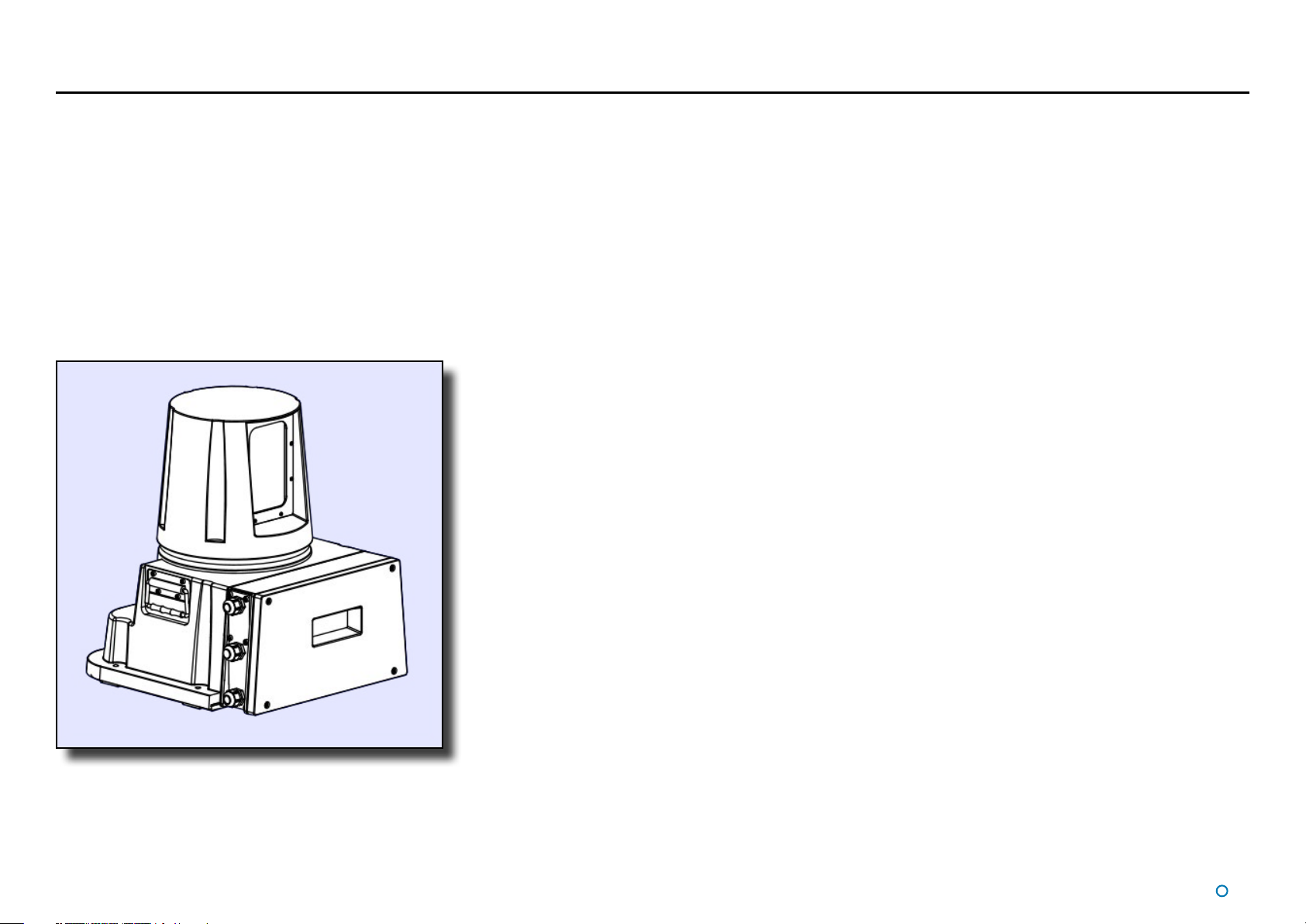
System Overview����������������������������������������������������������������������������������������������������������7
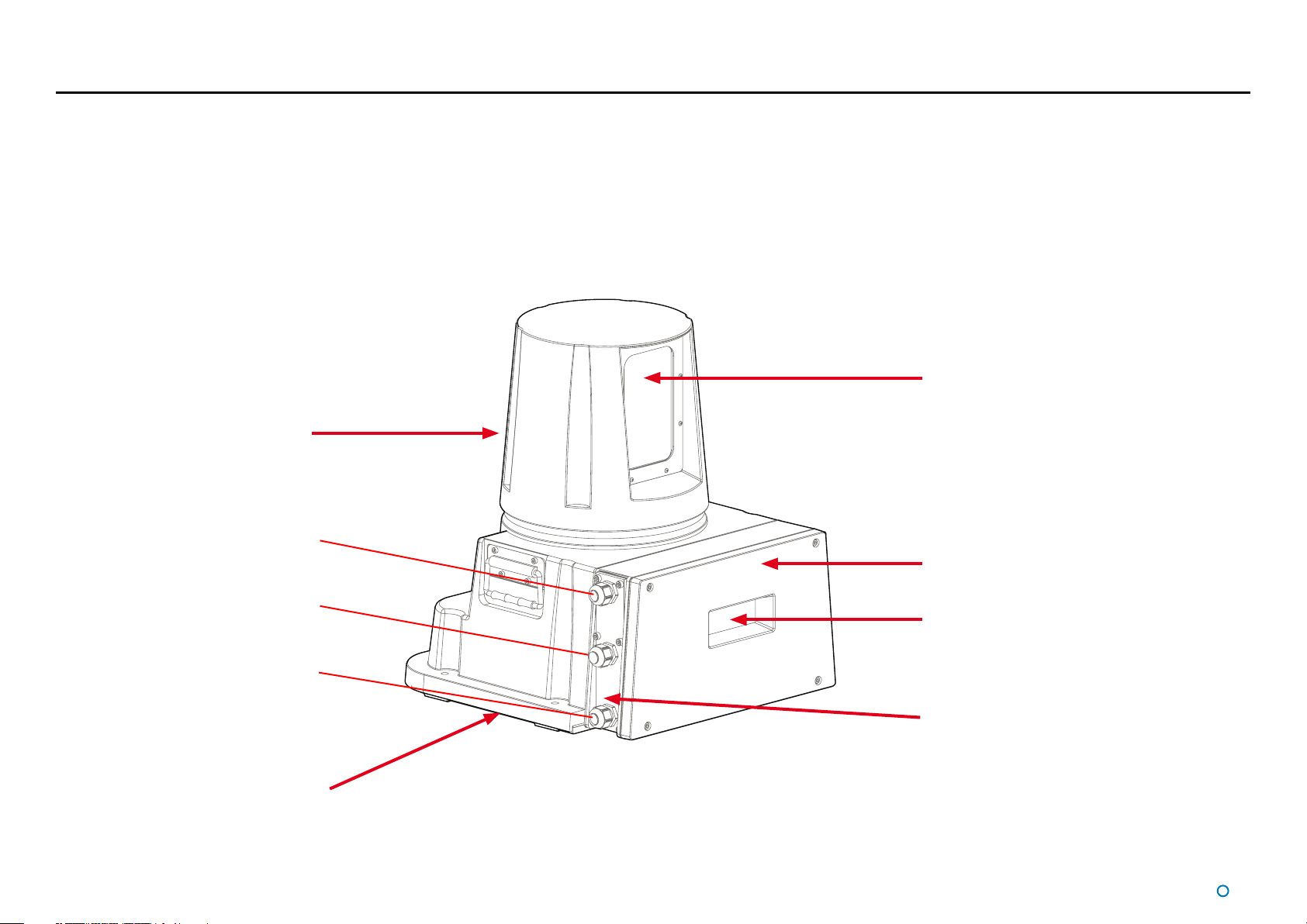
CyScan Sensor Part Names�����������������������������������������������������������������������������������������8
Serial Numbers & Software Versions��������������������������������������������������������������������������10
Product Label ��������������������������������������������������������������������������������������������������������������������������������������10
Software Version Information �������������������������������������������������������������������������������������������������������������� 10
Sensor Information Display ����������������������������������������������������������������������������������������11
Installing the Sensor Hardware ......................................................... 12
Where to Mount the Sensor ���������������������������������������������������������������������������������������13
Sensor Dimensions and Mounting Template��������������������������������������������������������������14
Installing the Cables ............................................................................... 15
Cable Specications ��������������������������������������������������������������������������������������������������16
UPS Specications�����������������������������������������������������������������������������������������������������17
CyScan Sensor Connections �������������������������������������������������������������������������������������18
To Connect a Cable to the CyScan Sensor����������������������������������������������������������������������������������������� 18
Connecting the Power Cable �������������������������������������������������������������������������������������������������������������� 18
Client and DP Feed Connections - Ethernet Client, Serial DP�����������������������������������19
Client and DP Feed Connections - Ethernet Client, Dual Serial DP���������������������������20
Client and DP Feed Connections - Serial Client, Serial DP ���������������������������������������21
Installing the Control PC....................................................................... 22
Installing CyScan Client Software onto a Type 2 or 3 Marine Processor �������������������23
Installing CyScan Client Software onto other Types of Computer�����������������������������24
Configuring the CyScan System......................................................... 25
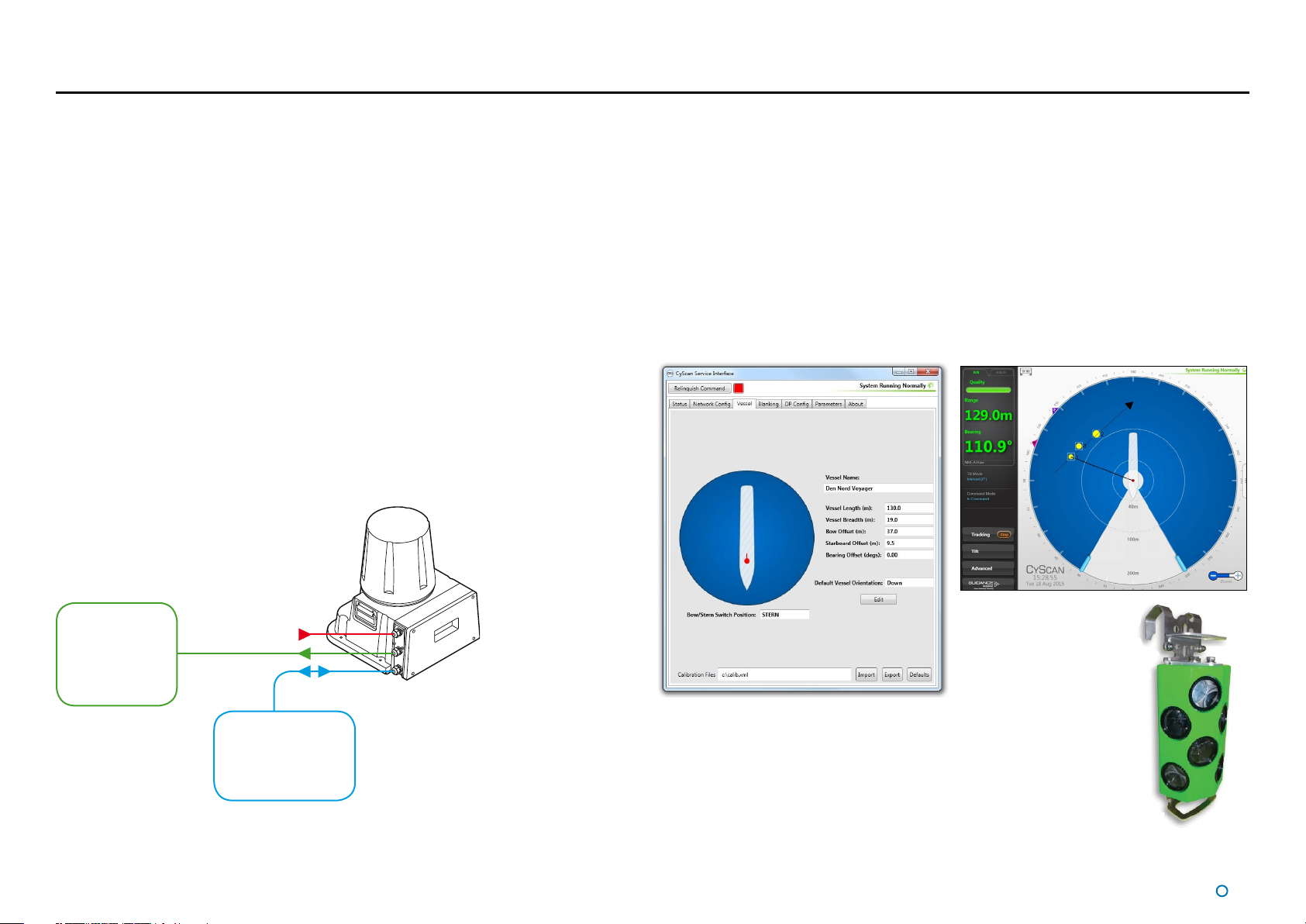
Using the CyScan Service Interface���������������������������������������������������������������������������26
Network Communication Settings �����������������������������������������������������������������������������27
Vessel Calibration�������������������������������������������������������������������������������������������������������28
Static Blanking Zones ������������������������������������������������������������������������������������������������30
DP Feed Conguration�����������������������������������������������������������������������������������������������31
System Parameters ����������������������������������������������������������������������������������������������������33
Additional Information ........................................................................... 35
Target Types ���������������������������������������������������������������������������������������������������������������36
Positioning and Mounting Targets������������������������������������������������������������������������������37
DP Message Types�����������������������������������������������������������������������������������������������������38
NMEA0183R Format ��������������������������������������������������������������������������������������������������������������������������� 38
NMEA0183P Format����������������������������������������������������������������������������������������������������������������������������38
ASCII17 Format ����������������������������������������������������������������������������������������������������������������������������������� 39
MDL Standard † ���������������������������������������������������������������������������������������������������������������������������������� 39
MDL Multi-Target † �����������������������������������������������������������������������������������������������������������������������������39
Nautronix Standard † �������������������������������������������������������������������������������������������������������������������������� 39
Artemis Mk IV † �����������������������������������������������������������������������������������������������������������������������������������39
Kongsberg Standard ��������������������������������������������������������������������������������������������������������������������������� 39
MT Custom DP String ������������������������������������������������������������������������������������������������������������������������� 40
Rolls-Royce Custom DP String �����������������������������������������������������������������������������������������������������������41
Part Numbers �������������������������������������������������������������������������������������������������������������42
Standard Components ������������������������������������������������������������������������������������������������������������������������42
Optional Components ������������������������������������������������������������������������������������������������������������������������� 42
Reective Targets (Optional)����������������������������������������������������������������������������������������������������������������42
CyScan MkIV Installation Checklist����������������������������������������������������������������������������43
Cable Routing Diagrams ��������������������������������������������������������������������������������������������44
Sensor Information Display - Error Messages������������������������������������������������������������50
Upgrading the Sensor Software Via the Remote Installer������������������������������������������52

l4
Table of Contents (continued)
Upgrading the Sensor Software Directly��������������������������������������������������������������������53
Remote Diagnostics ���������������������������������������������������������������������������������������������������54
The Kongsberg Maritime CyScan Sensor ������������������������������������������������������������������55
DP Message Types������������������������������������������������������������������������������������������������������������������������������55
Kongsberg (Custom) ���������������������������������������������������������������������������������������������������������������������������55
Client and DP Feed Connections - Ethernet Client, Serial DP ������������������������������������������������������������ 56
Client and DP Feed Connections - Ethernet Client, Dual Serial DP����������������������������������������������������57
Client and DP Feed Connections - Serial Client, Serial DP�����������������������������������������������������������������58
Document History ������������������������������������������������������������������������������������������������������62

l6
Welcome
Welcome to the CyScan Installer’s Guide. It explains how to mount and install the CyScan
system onto a vessel and how to install the CyScan Service Interface (CSI) and Dashboard.
An on-screen version of this document can be opened from the About tab of the CSI.
For Instructions on how to use CyScan, please see the CyScan Operator’s Guide (Doc
94-0353-4).
Note that the introduction of the CSI constitutes a significant change in the CyScan
configuration interface in comparison with the legacy console. There may also be further
improvements to the CSI in subsequent releases. Whilst we endeavour to describe its
functionality correctly in this document, we do not guarantee that it exactly represents the
version of the CSI that you are running.
!Note: Installation of a CyScan system should be carried
out by a suitably qualified and competent engineer.

l7
System Overview
CyScan is a high accuracy marine laser sensor. It provides positional information to a
vessel’s DP system, allowing it to keep station relative to a target structure or another vessel.
The CyScan system contains the following main parts:
• CyScan Sensor
• CyScan Client Software
• CyScan Targets
CyScan Sensor
The CyScan sensor is a rotating laser scanner. It is mounted on the vessel’s superstructure;
typically on the wheel-house.
The CyScan sensor can be installed in three ways:
• Ethernet Client, Single Serial DP (see page 19)
• Ethernet Client, Dual Serial DP (see page 20)
• Serial Client, Single Serial DP (see page 21)
CyScan
Sensor
DP
System
Client
Software
Computer(s)
Power
The key elements of the CyScan system
CyScan Client Software
The CyScan Service Interface (CSI) and CyScan Dashboard are software applications
used to configure, control and monitor the CyScan system. They are installed on one or
more marine-specification Type 2 Marine Processor or other computers running Microsoft
WindowsTM, usually mounted on the bridge near to the controls of the vessel’s DP system.
The CSI is used for system configuration and replaces the Service Access mode of the
Dashboard or Console in earlier versions of the CyScan system.
The Dashboard gives the DP operator control of the CyScan system and the data stream
being fed to the DP system.
The Ethernet version of the Dashboard can run on multiple computers across a network,
with one Dashboard in Command mode and the others in Monitoring mode.
CyScan Dashboard
CyScan Targets
One or more retro-reflective CyScan targets are mounted on the target
platform or vessel. The precise range and bearing of each target is used
to calculate the exact position of the CyScan vessel relative to the target
structure or vessel.
See on page 37 for more detail on CyScan targets. CyScan Rugged
Prism Target
CyScan Service Interface

l8
CyScan Sensor Part Names
The diagram below shows the key parts of the sensor unit and the various names that are
used throughout this guide:
Client Data
Power
DP Feed
Optical Window
Rotor
Base Plate
Sensor Information
Display
Access Plate
Cable Gland Plate

l9
CyScan Sensor Part Names (Continued)
Alternative model with 4 cable glands.
Client Data
Power
DP Feed 2
DP Feed 1

l10
Serial Numbers & Software Versions
Serial numbers and Software Version Numbers are used to identify the hardware configuration and product revision of each CyScan unit. They will be requested by Guidance Marine in the
event of an application service support call to the company.
Software Version Information
The About tab of the CyScan Service Interface displays software version
information and the sensor serial number.
CyScan Sensor
Product Label
CyScan Sensor
Part Number
CyScan Sensor
Serial Number
Product Label
The Part Number and
Serial Number can be
found on the product label
fixed to the CyScan unit,
see right.
Software Version
Information
CyScan Sensor
Serial Number

l11
Sensor Information Display
The Sensor Information Display shows the status of the sensor and its internal system throughout each period of operation.
Sensor Information Display Details
Below is a list of the messages that appear during normal startup and operation of the CyScan Sensor. The messages are
listed in the order they normally occur, when the system is left to startup and run without the user pressing any buttons.
Display Screen Message Description
CTRL BOOT Wtg cmd..
V1.5.0.0
Displays the current version of the boot loader (1.5.0.0 in this example).
Starting application The application is starting.
Starting receiver... The receiver is starting.
Running 10:35
Temp 25°C
The sensor and all its internal systems are now running or suspended etc.
(displayed as applicable). The system time and system temperature are also shown
Nav App Version
V4.9.3.87
Displays the software version number for the Navigator Application.
Rec App Version
V4.9.3.87
Displays the software version number for the Receiver application.
Ctrl App Version
V4.9.3.87
Displays the software version number for the Controller application.
Rec Boot Version
V4.9.3.87
Displays the software version number for the Receiver boot loader.
Ctrl Boot Version
V4.9.3.87
Displays the software version number for the Controller boot loader.
Congured Ethernet
UDP 192.168.2.228
(Ethernet system only) Displays the IP address of the Ethernet port.
IP0 192.168.2.228
MAC 050203441526
(Ethernet system only) Displays the MAC address of the Ethernet adapter.
Congured Serial
Serial Port 0: 38400
(Serial system only) Gives the baud rate of the client data serial port.
DP: NMEA0183R (raw)
Serial Port 1: 9600
Displays the DP message format and the baud rate of the DP feed serial port.
Pwr 0.8% Rev 234
Re 2 Puls 20
Displays the laser power and the number of revolutions completed by the sensor.
Also displays the number of reflections and the number of pulses detected in the last revolution.
T1:Range 5.6m
Bearing 166.7° S 11%
(When tracking a target) Displays the range, bearing and signal strength of the primary target.
Otherwise displays “T1: n⁄a”.
Sensor Code 1: 7085
Sensor Code 2: 5380
Recent sensor codes for use in troubleshooting.
Sensor
Information
Display

Service Connections
Stern
Bow
Stern
Bow
l13
Where to Mount the Sensor
Sensor Mounting Locations
The CyScan system is designed for permanent or semi-permanent installation on-board a
vessel. Often, a custom-fabricated plinth is used to provide the optimum height and location
for mounting the CyScan sensor.
On all types of vessel the sensor should be mounted:
• With an unobstructed view in the expected direction of the target structure or vessel.
• Well above sea level to prevent swamping or immersion.
• On a flat, rigid, horizontal surface able to support 30kg and receive 4x M8 fixing bolts.
• Allowing for easy access to the connector board and Sensor Information Display.
• Clear of VHF emergency band antennae, S-band and X-band ship’s radars (as far away
as possible but at least 5m, in all directions, from any radar).
• Clear of likely emissions from exhausts or other particulate sources to reduce the need
for cleaning the optical windows.
The sensor should be mounted with the Access Plate (see page 8)facing directly towards
either the bow (default) or the stern; parallel to the vessel’s fore and aft centre-line. Any
deviation from the centre-line alignment must be corrected in the CyScan Service Interface.
Exhaust emissions contain particulates which will degrade the optics.
WARNING:
If the CyScan sensor is mounted with the access plate facing towards the stern, the
BOW/STERN switch on the connector board must be set to STERN.
A typical mounting position is above the wheelhouse for a vessel with a
superstructure like that of a platform supply vessel.
Bow
Bow
Stern
Stern
Sensor
mounted with
access plate facing bow.
Ferrite Bead
Ethernet 1
Ethernet 0
Serial 0
Serial 1
AC
Power Power LED
VFD Screen
Fuses
Stern
Bow
Sensor
mounted with
access plate facing stern.

l14
Sensor Dimensions and Mounting Template
Sensor Clearance
The exact dimensions of the CyScan unit’s footprint are shown below.
The additional information shown on the right will be useful when mounting the CyScan
unit. Please refer to Document No: 94-0062-4 CyScan Mounting Template to view the
information in larger format.
Mounting Template
Mount the baseplate horizontally and aligned with the bow or stern as shown. By default
each sensor is configured to have the access plate facing towards the bow. This orientation
can be reversed if required to give easier access to the cables and access plate.
Allow 300mm
clearance at the
access plate to
manoeuvre internal
assemblies in/out.
Allow 150mm
clearance at either side
of the unit for use of
the lifting handles.
Allow 150mm
clearance for
access to the
rotor screws.
BOW (default)
or
STERN
NOT TO SCALE
STERN (de-
fault)or
BOW
All dimensions in mm
Ensure a clear
line of sight to the
Display Screen in
the access plate.
Allow a sensor height of 460mm
from the mounting plate, plus an
additional 30mm clearance to
remove the rotor from the shaft.
300
150
150
705
857
150
460
300
150 150
705
857
150
BOW (default)
or
STERN
STERN (default)
or
BOW
47
405
360
327
190
80
407
4 x 9 THRU
WARNING:
If the CyScan sensor is mounted with the access plate facing towards the stern, the
BOW/STERN switch on the connector board must be set to STERN (see page 13).

l15
Installing the Cables
This section contains the following pages:
• Cable Specications (page 16)
• UPS Specications (page 17)
• CyScan Sensor Connections (page 18)
• Client and DP Feed Connections - Ethernet Client, Serial DP (page 19)
• Client and DP Feed Connections - Ethernet Client, Dual Serial DP (page 20)
• Client and DP Feed Connections - Serial Client, Serial DP (page 21)

l16
Cable Specifications
The CyScan system is usually supplied without the cables that are necessary to connect the sensor to the DP system and the Client Software computer(s). Guidance recommends that
flexible multicore cables are used in all applications. Cables should meet the requirements of IEC 60228 Class 2 or Class 5. Cables must be supplied and fitted by the installer to match the
particular requirements for each vessel. All cables should be properly secured.
The cable glands will fit cables from 7-13mm diameter.
Use Description Guidance Marine Limited Part Numbers (40m lengths)
Serial Signal Wiring to DP
System Minimum 5-core shielded data
cable.
33-0122-3
Olflex Classic 135 CH xG 0.5 All cables should
be external marine
standard including
UV and chemical
resistance, 500V
rated voltage,
Diameter 7-13mm
and operate between
-40°C to +80°C.
Serial Signal Wiring
to Client Software
Computer(s)
Ethernet Connection
to Client Software
Computer(s)
Standard CAT 5e screened cable
(maximum length 90m). 33-0124-3
Power Cable 3 core cable. 33-0121-3
Olflex Classic 400 CP 3G 1.0
xis number of cores including Ground with each core 0.5mm2(minimum 5-core specifies 4 signal cores and 1 ground core).
Data cables should not be run across or next to power cables to avoid signal interference problems.
Refer to the cable routing diagrams on page 44 to determine which cables you require.

l17
UPS Specifications
The main power supply to the CyScan sensor and the computer(s) running the CSI and
Dashboard must come directly from a UPS (Un-interruptible Power Supply), which will also
act as the power disconnection point.
The CyScan system comprises the following components and the UPS system used must
meet these minimum specifications:
CyScan Sensor
• The UPS must be Marine Type Approved
• Output Power = 3W / 35 dBm
• Input Power = 45W
• Voltage Range = 85-264 Vac
• Peak Current draw at 110V = 1.14A RMS
• Nominal Current draw at 110V = 0.68A RMS
• Peak Current draw at 240V = 0.52A RMS
• Nominal Current draw at 240V = 0.4A RMS
Type 2 Marine Processor Power Adaptor
• Voltage Range = 100-240V
• Frequency Range = 50-60Hz
• Peak Current draw = 1.5A RMS
The CyScan UPS should be able to run on back-up power for at least the same duration as
that specified for the DP System UPS.
The power cable to the CyScan Sensor must be rated to withstand the maximum current
output of the UPS.
The specifications given above apply when the UPS is connected to a CyScan
system only.
Type 3 Marine Processor Power Adaptor
• Voltage Range = 100-240V
• Frequency Range = 50-60Hz
• Peak Current draw = 1.8A RMS
Hatteland Panel PC
• Voltage Range = 115 & 230V
• Frequency Range = 50-60Hz
• Nominal Current draw at 115V = 0.52A RMS
• Nominal Current draw at 230V = 0.26A RMS

l18
CyScan Sensor Connections
Connecting the Power Cable
1. Having fed the cable through the watertight cable gland, use the key provided to open
the ferrite and pass the cable through the centre of the ferrite.
2. Close the ferrite securely and ensure it is firmly attached to the inside of the CyScan
casing to prevent excessive movement.
3. Strip 10mm of insulation from the end of each of the three cable cores.
4. Connect the 3 cores to the appropriate terminals as labelled on the terminal block
(see right).
5. When you have connected the cores to the terminal block, use two cable ties to secure
the terminal block and cable together.
6. Plug the terminal block securely in to the socket on the connector board as shown on
the right.
Earth
Live
Neutral
To Connect a Cable to the CyScan Sensor
1. Remove the 4 screws from the access plate and remove the plate from the sensor unit
to expose the connector board. (See CyScan Sensor Part Names on page8).
2. Remove the screw head from the appropriate watertight cable gland. See CyScan
Sensor Part Names on page8 to identify the correct cable gland.
3. Feed the cable through the screw head and gland.
4. Connect the cable to the correct socket/terminal on the sensor connector board.
5. When all the connections have been made, replace the access plate and tighten all of
the cable glands to ensure a watertight seal.
Base of CyScan with the access plate removed to expose the connector board
Watertight
cable gland
Ferrite
and key
Ferrite Key
Ferrite secured around cable
Power terminals on
connector board
Terminal block with cable cores
connected
Cable ties
To Connect Cables to
Power/Serial Plugs:
Hook lever-tool into
slot above
connector-hole in
plug.
Whilst holding down
lever, insert cable
end into connector-
hole.
Release and remove
the lever-tool.
BOW/STERN switch
see page 13 for details

l19
To connect an Ethernet Sensor with Ethernet to the Client and Serial to the DP Feed:
Connect Ethernet Port 0 to the Client Computer and Serial Port 1 to the DP system.
Configure the serial connections as shown below:
RS422 Link
to Vessel’s
DP System
Mains Power
85–264V AC
45–65Hz 45W
Ethernet
Link to
Client
Computer
Ferrite Bead
Ethernet 1
Ethernet 0
Serial 0
Serial 1
Power Power LED
VFD Screen
Fuses
Stern
Bow Service Connections
†Contact Guidance
Marine if
alternative settings
are required.
To Connect Cables to
Power/Serial Plugs:
Hook lever-tool into
slot above
connector-hole in
plug.
Whilst holding
down lever, insert
cable end into
connector-hole.
Release and remove
the lever-tool.
Client Network Protocol:
Ethernet
Default Ethernet Settings:†
IP Address: 192.168.0.86
Subnet Mask:
255.255.255.0
1 RX-
2 RX+
3 TX-
4 TX+
5 GND
6 Test
7 GND
8 +24V
DP
Feed *
Serial 1
*+24V output on pin 8 of
both serial ports can be
used to power a 100mA data
converter, if required.
RS422 Link
9600 baud
8 bits
1 stop bit
No parity
Client and DP Feed Connections - Ethernet Client, Serial DP

l20
To Connect an Ethernet Sensor with Ethernet to the Client and Serial to Two DP Systems:
Connect Ethernet Port 0 to the Client computer, Serial Port 0 to DP System 1 and Serial Port 1 to DP system 2.
Configure the serial connections as shown below:
1 RX-
2 RX+
3 TX-
4 TX+
5 GND
6 Test
7 GND
8 +24V
DP
Feed 2
RS422
Link to DP
System 1
Mains Power
85–264V AC
45–65Hz 45W
*
Serial 1
*+24V output on pin 8
of both serial ports can
be used to power a
100mA data converter,
if required.
Ferrite Bead
Ethernet 1
Ethernet 0
Serial 0
Serial 1
Power Power LED
VFD Screen
Fuses
Stern
Bow Service Connections
RS422 Link
9600 baud
8 bits
1 stop bit
No parity
Ethernet
Link to
Client
Computer
To Connect Cables to
Power/Serial Plugs:
Hook lever-tool into
slot above
connector-hole in
plug.
Whilst holding
down lever, insert
cable end into
connector-hole.
Release and remove
the lever-tool.
RS422
Link to DP
System 2
1 RX-
2 RX+
3 TX-
4 TX+
5 GND
6 Test
7 GND
8 +24V
DP
Feed 1 *
Serial 0
Client and DP Feed Connections - Ethernet Client, Dual Serial DP
Client Network Protocol:
Ethernet
Default Ethernet Settings:†
IP Address: 192.168.0.86
Subnet Mask:
255.255.255.0
Other manuals for CyScan
1
Table of contents
Other GUIDANCE MARINE Marine Equipment manuals

GUIDANCE MARINE
GUIDANCE MARINE RadaScan View Assembly instructions

GUIDANCE MARINE
GUIDANCE MARINE SceneScan User manual

GUIDANCE MARINE
GUIDANCE MARINE Artemis Mk6 Manual

GUIDANCE MARINE
GUIDANCE MARINE Artemis Mk6 Assembly instructions

GUIDANCE MARINE
GUIDANCE MARINE RangeGuard Assembly instructions

GUIDANCE MARINE
GUIDANCE MARINE CyScan AS Manual

GUIDANCE MARINE
GUIDANCE MARINE RadaScan View Assembly instructions

GUIDANCE MARINE
GUIDANCE MARINE 20- Series Assembly instructions

GUIDANCE MARINE
GUIDANCE MARINE RangeGuard Monopole Manual