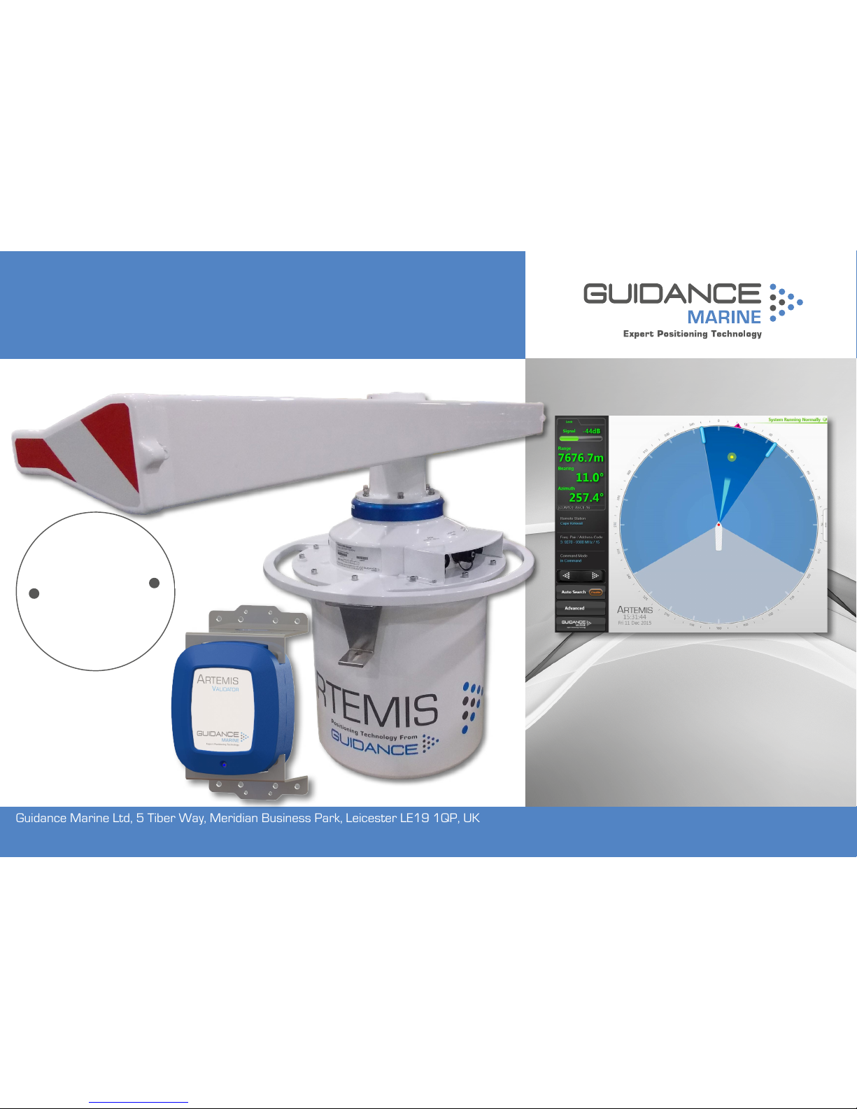
GUIDANCE MARINE Artemis Mk6 Manual

Guidance Marine Ltd, 5 Tiber Way, Meridian Business Park, Leicester LE19 1QP, UK
Artemis Mk6 Operator’s Guide
featuring
Artemis Dashboard
with validation feature
W
A
R
R
A
N
T
Y
S
e
e
o
u
r
s
t
a
n
d
a
r
d
t
e
r
m
s
o
f
s
a
l
e
Q
U
A
L
I
T
Y
A
S
S
U
R
E
D
3
YEAR
www.guidance.eu.com
www.marine.direct

Guidance Marine Ltd,
5 Tiber Way
Meridian Business Park
Leicester
LE19 1QP
UK
Tel: +44 116 229 2600
UK Support: +44 116 229 2665
(365 days a year, 08:00 - 20:00 hours UTC)
USA Support: +1 504 305-1120
Asia Support: +65 6734 6365
Web: www.guidance.eu.com/customer-support
Copyright © Guidance Marine Limited. All Rights Reserved.
Copyright in the whole and every part of this document belongs to Guidance Marine Limited
(the “Owner”) and may not be used, sold, transferred, copied or reproduced in whole or in
part in any manner or form or in or on any media to any person other than in accordance with
the terms of the Owner’s Agreement or otherwise without the prior written consent of the
Owner.”Windows” is a trademark of Microsoft Corporation. All other brand or product names
are trademarks or registered trademarks of their respective companies or organisations.
Serial No:
Date of Shipment from UK:
Sensor Software Version: Dashboard Software Version:
Artemis Mk6 Operator’s Guide
Issue Date: 23/02/2017
Document No: 94-0440-4
0891
FCCID: VYMARTEMIS
This radio is intended for use in occupational/controlled conditions where users have
full knowledge of their exposure and can exercise control over their exposure to meet
FCC limits. This radio device is NOT authorized for general population, consumer, or
any other use.
This device emits radio frequency (RF) energy when transmitting. Make sure to
observe all RF energy exposure standards when installing, testing and operating this
radio equipment. Proper operation of this device under normal conditions results in
user exposure to RF energy below standard acceptable limits. To maintain a safe
distance, do not operate the equipment when a person is within 18cm (0.6 feet) of
the antenna.

l3
Document History
Document Number Changes Issue Date
94-0440-4-A First release of Artemis Mk6 Operator’s Guide 28/06/2016
94-0440-4-B Artemis Mk6 Operator’s Guide (inclusion of Artemis Validator) 23/02/2017

l4
Introduction
System Overview...................................................................................................... 6
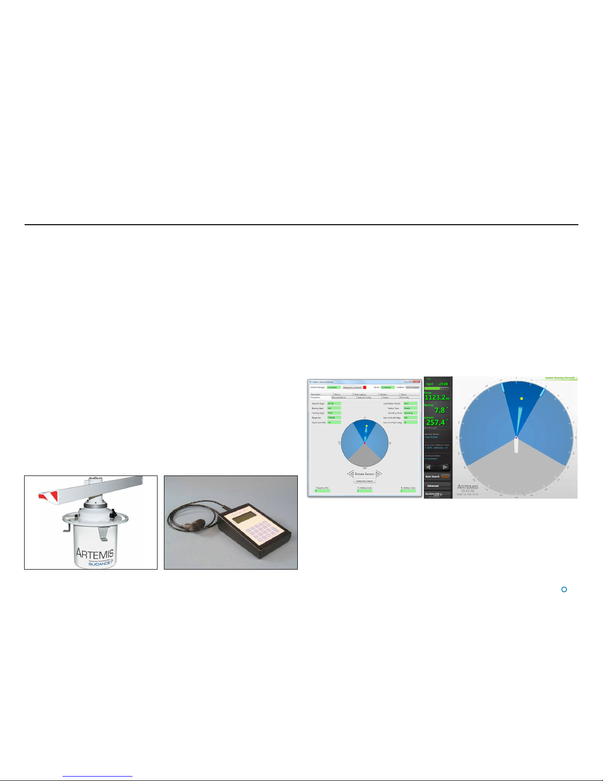
Getting Started
Start Up and Shut Down .......................................................................................... 9
Start Up.............................................................................................................................................. 9
Shut Down ......................................................................................................................................... 9
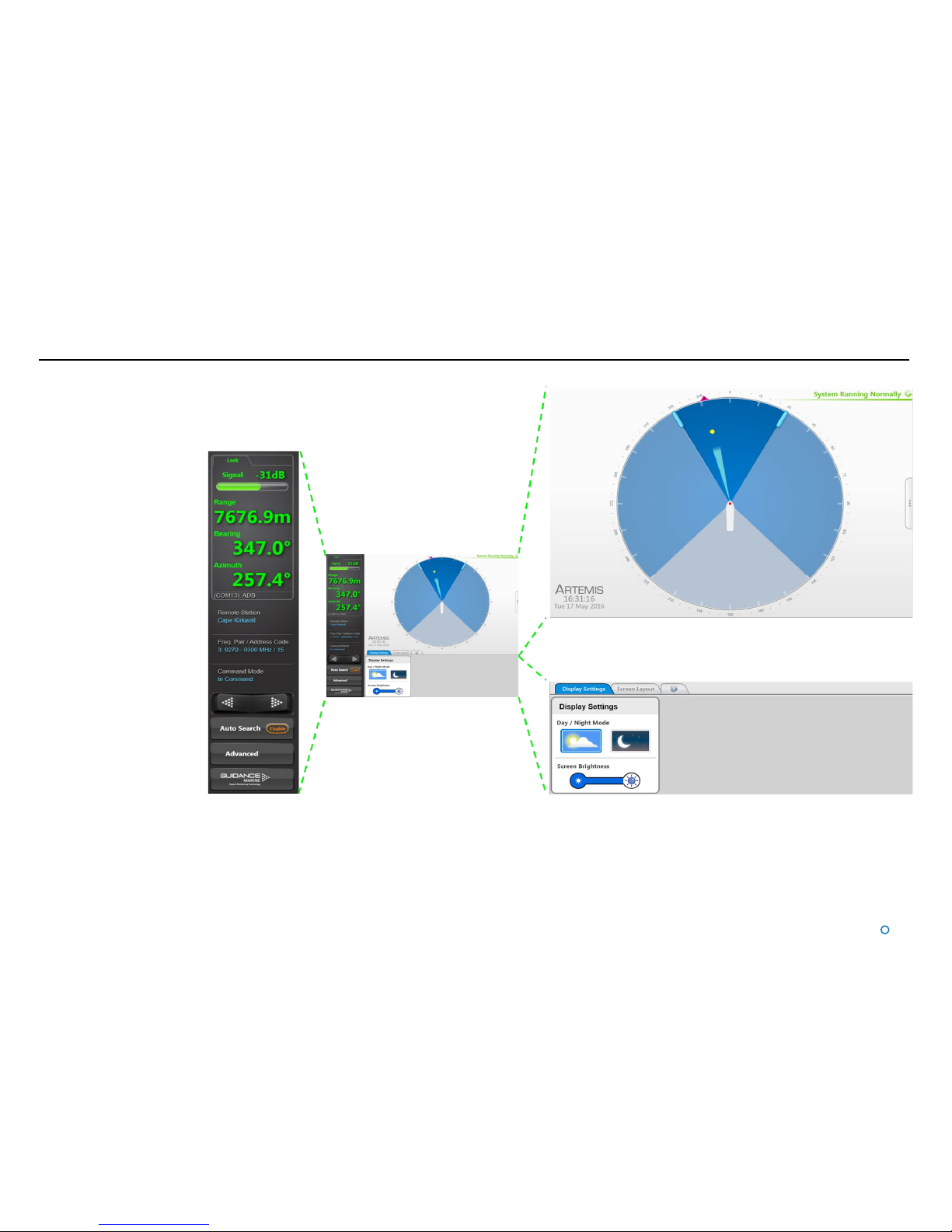
Screen Contents..................................................................................................... 10
Main Screen and Bird's Eye View (BEV) .......................................................................................... 11
System Status.................................................................................................................................. 12
Side Bar ........................................................................................................................................... 13
Hotkey Buttons ................................................................................................................................ 14
Menu Pane....................................................................................................................................... 15
Display Options ...................................................................................................... 16
Display View..................................................................................................................................... 16
Screen Layout Mode........................................................................................................................ 16
Vessel Orientation ............................................................................................................................ 17
Basic Operation
Tracking Overview .................................................................................................. 19
Selecting a Remote Station.................................................................................... 20
To Select a Different Remote Station:.............................................................................................. 20
Adjusting the Scan Sector...................................................................................... 21
To Adjust the Scan Sector: .............................................................................................................. 21
Tracking Information Quality................................................................................... 22
DP Feeds................................................................................................................ 23
To View DP Feed Details:................................................................................................................. 23
Multi-Dashboard Artemis Systems
Artemis Dashboard – Command Mode.................................................................. 25
Artemis Dashboard - Monitoring Mode.................................................................. 26
Support Information
Serial Numbers and Software Versions.................................................................. 28
Network Communications Settings........................................................................ 29
Sensor Settings ...................................................................................................... 30
Using the On-Screen Keyboard ............................................................................. 31
To enable the on-screen keyboard .................................................................................................. 31
To use the on-screen keyboard ....................................................................................................... 31
Working with Alarms............................................................................................... 32
Artemis Validator
Using a Permanently Installed Artemis Validator.................................................... 35
Additional Information
International Standards Compliance...................................................................... 38
System Specications............................................................................................ 39
Index....................................................................................................................... 41
Table of Contents

l5
Introduction
Welcome to the Artemis Mk6 Operator’s Guide. It explains how to use the Artemis system
once it has been fully installed. For instructions on how to install the system onto a vessel,
refer to the document 94-0441-4 Artemis Mk6 Installer’s Guide.
The System Overview on page 6 describes the different components of the system and
how they work together.
The Getting Started section on page 8 explains how to get the system up and running and
how to shut it down again. It also details what you will see on the Dashboard screen when
the system is running, and how to interpret the information.
The Basic Operation section on page 18 deals with selecting searching for and tracking
the remote station.
The Multi-Dashboard Artemis Systems section on page 24 explains how two or more
Dashboards operate simultaneously in an Artemis system.
Further useful information is included in the Support Information section on page 27.
Note that whilst we endeavour to describe system functionality correctly in this document,
we do not guarantee that it exactly represents the version of the system that you are
running, particularly after any future upgrades to the software.

l6
The Artemis microwave-based position reference system provides accurate positional data
to marine Dynamic Positioning (DP) control systems. It enables automated approach and
station keeping relative to a rig or platform, or to another vessel.
The standard Artemis system consists of:
• Two Sensors, user-configurable as a Mobile Station and a Fixed Station. An Alternative
configuration replaces the fixed station with a Beacon Station. In this configuration, the
system does not provide an azimuth measurement.
• The Artemis Control PC, a Windows-based marine specification computer, running the
control software.
• Artemis Client PC(s), optional computers used where more than one installation of the
Artemis Dashboard software is required.
• Hand-held Operating Panel (or Pendant).
Antenna Units
The Mobile Station is mounted on the DP-Equipped vessel, ideally at the top of the main
mast. The Fixed Station is installed on a fixed platform if absolute positioning is needed or
on a moving platform or structure to provide relative positioning.
Hand-held Operating Panel (Pendant)
A hand-held unit that can be connected to a station or Beacon unit to read and set system
parameters during installation. It can also be used to view positional data once the system
is in operation. This is an optional diagnostic aid.
System Overview
Artemis Control Software
The following applications run on the Artemis Control PC, usually mounted on the bridge
near to the controls of the vessel’s DP system:
• Manager – This Windows service running on the Artemis Control PC can be configured
to run automatically after the PC powers up. It provides a single point of control for an
Artemis sensor through which the other components communicate.
• Service Interface – Used for system installation and maintenance, it allows network
communications to be configured and parameters on an Artemis Station to be viewed and
set. It displays the state of connected Artemis Dashboard(s) and can be used to take basic
control of the station.
• Dashboard – Used to control and monitor normal system operation. Up to five instances
of the Dashboard can run simultaneously on the Control PC and Client PCs, but only one
of these can exercise control at any given time; the others can only be used to monitor the
system.
An Antenna Unit (Mobile or Fixed Station) An Operating Panel
Artemis Service Interface Artemis Dashboard
Explosion-Proof Antenna Unit/Beacon
An antenna unit or beacon can be made safe for operation in hazardous zone 2 conditions
with the use of a pressurisation unit. This forces clean air into the housing of the antenna
unit or beacon to prevent the ingress of explosive or flammable gases that might otherwise
be ignited by electrical sparks. Contact Guidance Marine for details.

l7
System Overview (Continued)
System Operation
In order to provide positional data to the vessel’s DP system, the Artemis system needs to
be “locked”. In this state, the antennae of the Fixed and Mobile Stations are facing each
other and automatically track by maintaining a continuous microwave link.
The distance between the sensors is obtained from the travel time of the microwave signal,
measured by means of coded interruptions in the continuous wave. The bearing of the
Fixed Station, with respect to the centre line of the vessel, is measured using a precision
shaft encoder.
The Fixed Station measures the azimuth and reports it to the Mobile Station. The azimuth
is the horizontal angle between a reference direction and the Mobile Station, with its vertex
at the Fixed Station.
Beacon Unit
Used instead of a standard rotating Fixed Station on a fixed platform for absolute
positioning, or on a moving platform or structure for relative positioning. The antenna of a
Beacon unit does not rotate.
Semi-omni antenna with waveguide, 100° beam width
NORTH *
FIXED
STATION
AZIMUTH
RANGE
* OR ANY OTHER REFERENCE DIRECTION
HEADING
MOBILE
STATION
NORTH *
RELATIVE MOBILE ANTENNA BEARING
North*
Fixed
Station
Azimuth
Range
*or any other reference direction
Heading
North*
R
e
l
a
t
i
v
e
M
o
b
i
l
e
A
n
t
e
n
n
a
B
e
a
r
i
n
g
Mobile Station
Layout of a Standard Artemis System
Beacon Antenna
NORTH *
FIXED
STATION
AZIMUTH
RANGE
* OR ANY OTHER REFERENCE DIRECTION
HEADING
MOBILE
STATION
NORTH *
RELATIVE MOBILE ANTENNA BEARING
Fixed
Station
North*
R
e
l
a
t
i
v
e
M
o
b
i
l
e
A
n
t
e
n
n
a
B
e
a
r
i
n
g
Mobile Station
A
z
i
m
u
t
h
Range
Layout of an Artemis Beacon System
The beam width of an antenna unit (Fixed or Mobile Station) is approximately 2°.

l8
Getting Started
This section covers the basics of using the Artemis system.
It contains the following pages:
• Start Up and Shut Down section on page 9
• Screen Contents section on page 10
• Display Options section on page 16

l9
Start Up and Shut Down
Start Up
To Start Artemis Dashboard
1. Ensure that the local station is powered on.
2. Double-click on the Artemis Dashboard icon.
(Or run the Artemis Dashboard application from:
Start > All Programs > Guidance Marine Ltd > Artemis > Artemis Dashboard).
3. The Dashboard display screen will appear. If the sensor is currently suspended, the
main part of the screen will be greyed out. Click on the Resume button in the side bar
in order for the sensor to begin transmitting and for the results to be displayed on the
screen. If the sensor was already transmitting, any remote station to which it is locked
will be displayed straight away.
Shut Down
To Disconnect, Exit or Suspend
(Click on the Guidance button in the lower left corner of the screen. This reveals the
Guidance Home Menu, which contains different sets of buttons depending whether the
Dashboard is in Command Mode, and whether it is tracking a remote station. Buttons are
explained below.
• Disconnect - Ceases communications between the local station and the Dashboard
computer. The local station is unaffected and if tracking is in progress, it will
continue.
• Exit - Closes the Dashboard without affecting the sensor.
• Suspend – Only available when the Dashboard is in Command Mode and the local
station is not tracking a remote station. Places the local station into a ‘sleep mode’
in which it ceases to transmit. The Dashboard remains active and connected to the
sensor ready for operations. This mode is suitable for use when travelling between
locations.
• Suspend and Exit – Same as Suspend, except that it closes the Dashboard
program.
Dashboard screen with local station suspended
Dashboard screen with local station scanning Guidance Home Menu in
different contexts
Side Bar

l10
Screen Contents
The Artemis Dashboard screen is split into
three distinct sections, these are:
• Main Screen and Bird’s Eye View
(BEV) (see page 11)
• Side Bar (see page 13)
• Menu Pane (see page 15)
Side Bar
Dashboard
Main Screen and Bird’s Eye View
Menu Pane

l11
Main Screen and Bird's Eye
View (BEV)
The circular BEV depicts the operational area
of the Artemis system from above. The red dot
at the centre represents the local Antenna Unit
mounted on its vessel and the arc through which
it can rotate corresponds to the combined blue
areas. A grey exclusion zone can be configured
(using the End Limit parameters) if there is a
physical obstruction that prevents the antenna
from turning through 360°.
The current direction and movement of the radar
beam is indicated by the slim, light blue triangle.
If the local station is locked onto a remote
station, this is represented by a yellow dot. If
the remote station is configured as “Floating”
rather than “Fixed”, the outline of its vessel is also
shown (with its bow aligned to 0° azimuth).
Vessel Outlines
Where a vessel outline is shown, its direction
is significant, but its size, exact shape and the
position of the Artemis station within it is arbitrary.
Scan Limits
If the local station is not locked onto a remote
station, and Auto Search is enabled, the beam
moves to and fro across the configured scan
sector. The size of this sector (the dark blue area)
can be adjusted (see Adjusting the Scan Sector
on page 21).
Radial Markers
These form an angular scale in degrees,
clockwise around the circumference of the BEV.
Zero is defined by the bow of the local vessel.
Screen Contents (Continued)

l12
Screen Contents (Continued)
System Status
This consists of two fields:
Primary
The primary part of the status display is in the upper-right corner of the Main Pane. It
indicates the current status of the system:
• System Running Normally
• System Suspended
• System Disconnected
• Local Connection Operational
• Communications ERROR
Secondary
The secondary status display is located in the lower right corner of the Main Pane and
is normally hidden. It displays a flashing message for a number of seconds in order to
confirm an action taken by the user (see below). It can also display a persistent, static
message if there is a communications problem.

l13
Screen Contents (Continued)
Side Bar
The Side Bar, the black pane to the left of the BEV, contains control and display
components in addition to the coordinates pane.
After pressing the
Guidance button:

l14
Hotkey Buttons
Selecting the Hotkeys tab on the right-hand side of the Bird's Eye View (BEV) activates the
Dashboard Hotkeys menu.
Screen Contents (Continued)
The following keys - and the corresponding buttons on the Dashboard Hotkeys menu - act as
shortcuts to application functions.
F1 Help Menu.
F2 Rotates the vessel clockwise.
F3 Rotates the vessel anti-clockwise.
F4 Toggles between the default BEV Layout Mode and Coordinates Layout Mode.
F5 Toggles between enlarged and standard-sized representation of the remote station.
F6 Toggles between the Day View and Night View.
F7 Toggles between the About System pane and the full BEV or Coordinates display.
F10 Takes a snapshot of the screen and stores the image in the file desktop.bmp, at the
configured location for data logging (defined by the LogPath parameter in the config.ini
file, in the Artemis Dashboard installation folder).
F11 Enables or Disables the On Screen Keyboard function.
Esc When in operation confirmation mode, cancels the current operation request; in all
other modes, brings back the full BEV or Coordinates screen.
Return
When in operation confirmation mode, confirm the current operation request.
Hotkeys Tab

l15
Screen Contents (Continued)
Menu Pane
The Menu Pane, located across the bottom of the Dashboard screen, is not always visible.
It appears when the Auto Search or Advanced buttons at the foot of the side bar are
pressed, which causes the Main Screen to contract upwards. Clicking the same button for
a second time causes the Menu Pane to disappear and the main screen to be restored to
full size.

l16
Display Options
Display View
To provide ample visibility during daytime operation and to limit glare during night shifts, the
Artemis Dashboard offers two display modes: Day View and Night View. In either mode the
brightness can be further adjusted by the Screen Brightness control.
To Change the Day/Night View and Adjust Brightness:
1. If the Guidance Home Menu is open in the Side Bar, close it by clicking on the
Guidance button.
2. Navigate to Advanced > Display Options > Display Settings.
3. Click on the Day View or Night View symbol.
4. Click on the left side of the Screen Brightness control to dim the screen and on the
right to make it brighter.
5. Alternatively, use the keyboard shortcut F6 or the Day/Night Mode button in the
Dashboard Hotkeys menu to switch between Day View and Night View.
Screen Layout Mode
By default, the main area of the Dashboard screen contains the Bird’s Eye View (BEV) and
if the local and remote stations are locked, the positional coordinates are displayed in the
upper part of the side bar. However, it is possible to swap these around so that the main
area shows the coordinates in extra-large text and the side bar contains a miniature BEV.
To Select the Screen Layout Mode:
1. Navigate to Advanced > Display Options > Screen Layout.
2. Select BEV or Coordinates.
OR
Click on the upper part of the side bar to toggle between the two layout modes.
Example Day View
Example Night View
Screen Layout Mode = BEV
Screen Layout Mode = Coordinates
Hotkey Buttons

l17
Display Options (Continued)
Vessel Orientation
The Artemis Dashboard supports four different arrangements of the Bird’s Eye View so that
the operator can choose the one which best represents his surroundings.
For instance, if the operator is facing forward when using the Dashboard, he would want
the bow of the vessel in the BEV to point upwards, so that a remote station located on the
starboard side of the vessel is shown on the right-hand side of the BEV.
To set Vessel Orientation:
1. Click on Advanced > Display Options > Screen Layout.
2. Click on the vessel outline that points in the required direction.
Alternatively, rotate the vessel clockwise by clicking F2 or the Rotate Vessel Clockwise
Hotkey. Rotate anti-clockwise by clicking F3 or the Rotate Vessel Anti-Clockwise
Hotkey.
Hotkey Buttons

l18
In order for the Artemis system to output positional data to a vessel’s DP system, the local
station needs to be tracking a remote station. This section explains how to achieve this.
It contains the following pages:
• Tracking Overview section on page 19
• Selecting a Remote Station section on page 20
• Adjusting the Scan Sector section on page 21
• Tracking Information Quality section on page 22
• DP Feeds section on page 23
Basic Operation

l19
Tracking Overview
When an Artemis-equipped vessel moves within operating range of a remote station, the
two stations will lock on to each other if the following conditions are met:
• The correct remote station has been selected within the vessel’s Artemis Control Software
(see Selecting a Remote Station on page 20).
• The radar beams from both stations are illuminating each other.
In order to fulfil the second condition, the scan sectors of each station should be set up to
include the direction in which the other is located. In the case of a fixed station mounted
on a rig or on land, it should already be configured to search in the directions from which
vessels normally approach. For the mobile station on board a vessel, it may be necessary
to widen the scan sector in order to find the fixed station (see Adjusting the Scan Sector
on page 21).
In order to locate the remote station within the scan sector, the beam direction can be
altered either manually or automatically:
• Rotate the beam manually using the rocker switch on the side bar. Click the left-hand
side of the switch to move the beam in a counter-clockwise direction by a small amount.
Similarly, click the right-hand side to move in a clockwise direction. Click repeatedly or
hold the switch down to move further.
• Click the Enable button embedded within the Auto Search button in order to search
automatically. This causes the beam to sweep from side to side across the scan sector
until it locks onto the remote station, or until Auto Search is disabled.
When the stations are locked, the remote station is represented on the BEV by a yellow
dot, the size of which varies with the strength of the received signal. If the remote station
has a structure type of Floating, an outline of its vessel is shown (with its bow aligned to 0°
azimuth).
Once a lock has been achieved, DP feed messages are output via the configured DP
channel(s). The position of the remote station and its signal strength are displayed at the
top of the side bar (or on the main screen if Coordinates Layout Mode has been selected).
(see Tracking Information Quality on page 22).
Leaving Auto Search enabled on the local station causes the beam to search for the remote
station if it is lost (e.g. due to another vessel passing across the line of sight).
If the local vessel is station keeping, or is moving along a trajectory such that the bearing
of the remote station remains about the same, you may wish to narrow the scan sector
around the remote station. This reduces the time required to scan for a remote station.

l20
Selecting a Remote Station
Although the local Artemis station tracks only one remote station at a time, it can be configured with a list of multiple prospective stations (see Artemis Mk6 Installer’s Guide). The side bar
of the Dashboard screen displays the description of the currently selected remote station, its address code and the frequency pair used when the local station communicates with it.
To Select a Dierent Remote Station:
1. Ensure that the Dashboard is in Command Mode (if not, click on the Guidance button then Take Command).
2. Click on the Auto Search button on the side bar.
This causes the Remote Stations Menu Pane to open. The description of the currently selected remote station has a green background.
3. Select a different remote station by clicking on its description in the list.
The details of the selected remote station are displayed in the right-hand side of the pane.
4. Click on Select Remote Station.
The description of the newly selected remote station now has a green background.
Other manuals for Artemis Mk6
1
This manual suits for next models
1
Table of contents
Other GUIDANCE MARINE Marine Equipment manuals

GUIDANCE MARINE
GUIDANCE MARINE 20- Series Assembly instructions

GUIDANCE MARINE
GUIDANCE MARINE RadaScan View Assembly instructions

GUIDANCE MARINE
GUIDANCE MARINE RadaScan View Assembly instructions

GUIDANCE MARINE
GUIDANCE MARINE RangeGuard Monopole Manual

GUIDANCE MARINE
GUIDANCE MARINE SceneScan User manual

GUIDANCE MARINE
GUIDANCE MARINE CyScan AS Manual

GUIDANCE MARINE
GUIDANCE MARINE Artemis Mk6 Assembly instructions

GUIDANCE MARINE
GUIDANCE MARINE RangeGuard Assembly instructions

GUIDANCE MARINE
GUIDANCE MARINE CyScan Assembly instructions