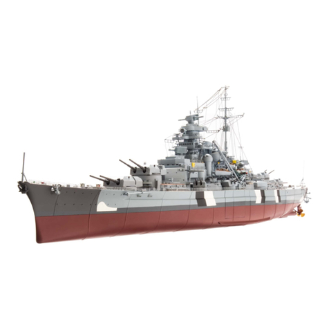
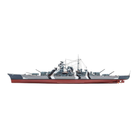
Hachette AGORA BISMARCK THE LEGENDARY BATTLESHIP Manual

Pack 07 |Build Instructions
Your 1:200 scale model of the legendary battleship Bismarck is packed with
intricate details which precisely replicate every aspect of this state-of-the-
art warship. Each piece has been created using premium quality materials to
bring maximum enjoyment during your complete build.
In your seventh model pack, you will assemble:
© 2020 Hachette Partworks Ltd.
North America Edition by Agora Models
STAGE 69: MOTOR FOR THE THIRD 15CM GUN
STAGE 70: THE FOURTH 15CM GUN TURRET
STAGE 71: THE NEXT KEEL SECTION
STAGE 72: MOTOR FOR THE FOURTH
15CM GUN
STAGE 73: GEAR ASSEMBLY FOR THE SECOND
38CM GUN
STAGE 74: ELEVATION MOTOR FOR THE
SECOND 38CM GUN TURRET
STAGE 75: DETAILS FOR THE UPPER DECK
STAGE 76: ROPE REELS AND FUNNEL DETAILS
STAGE 77: HULL SECTION AND FUNNEL
DETAILS
STAGE 78: FINAL DETAILS FOR THE FUNNEL
STAGE 79: THE NEXT HULL SECTION
STAGE 80: THE TWO AIRCRAFT HANGARS

Not suitable for children under the age of 14. This product is not a toy and is not designed for use in play. Keep
the parts out of the reach of small children. Some parts may have sharp edges. Please handle them with care.
Advice from the experts
Spare screws are included with each part. Occasionally, you may
be instructed to keep spare or unused screws for a later stage.
Keep these spares in a safe place and label them correctly.
Please make sure you don’t mix up the screws. They look quite
similar, but the threads do vary slightly. Using the wrong screws
may damage the parts.
When securing parts together using multiple screws, fit each
screw loosely to ensure all the parts are correctly aligned before
gently tightening them firmly, but not overtight, in the order in
which you placed them.
Your screwdriver can be magnetised by stroking it with a magnet
(fridge magnet, etc.) enabling it to hold the screws and make
assembly easier.
If a screw is tight going into a metal part, do not force it as you
may shear the head off. Remove it and put a tiny smear of Vaseline,
soap or light oil on the thread. That will lubricate it and make it
easier to drive home.
During the course of this build, you will receive many pieces that
you will assemble immediately – following the instructions in the
corresponding stage – and other pieces that you should store
safely to one side, for use in future assembly stages.
22
AGORAMODELS BISMARCK PB
AGORAMODELS BISMARCK

01. PREPARING THE MOTOR
01 02
PB
6901 6902
6903
6904 6905
6905 6905
6904
6904
STAGE 69
MOTOR FOR THE THIRD 15cm GUN
COMPONENTS CHECKLIST
69-01: Motor
69-02: Cog
69-03: Motor housing
69-04: Cable label
69-05: Cable for the gun motor
PB: Three 2 x 5mm PB screws
Wrap the label around one end of the cable 69-05,
close to one of the connectors.
Take the cable 69-05 and the cable label 69-04.
Remove the label from its backing.
33
AGORAMODELS BISMARCK PB
AGORAMODELS BISMARCK

03
04
Fit the connector on the unlabelled
end of cable 69-05 into the socket in
the circuit board on the motor 69-01.
Take the upper deck structure
19-01/22-01/48-01 and carefully
turn it upside down. Fit the motor
69-01 into the holder on the
underside of deck section 48-01.
The teeth of cog 69-02 engage
with cog 67-04 (arrow).
Fit the cog 69-02 over the shaft of the
motor 69-01, as shown.
01
6901
6905
6901
6902
02. FITTING THE MOTOR TO THE UPPER DECK
6902
6901
4801
6704
44
AGORAMODELS BISMARCK 5
AGORAMODELS BISMARCK

6901
6903 PB
6903
PB
02
03
Fit the motor housing 69-03 over
the motor 69-01. The two screw holes
on the side of the cover should align
with the screw sockets on the underside
of the upper deck.
Whilst supporting the deck from
below, fix the motor housing in place
with two PB screws.
Completed work
The motor for the third 15cm gun
has been fitted to the underside
of the upper deck.
5
4
AGORAMODELS BISMARCK 5
AGORAMODELS BISMARCK

01. ASSEMBLY OF THE 15cm GUN TURRET
01
PB
2 x 5
PB
1.7 x 6
PWB
7001
7007
7008
7005 7006
7002 7003 7004
7001
7006
7005
STAGE 70
THE FOURTH 15cm GUN TURRET
COMPONENTS CHECKLIST
70-01: 15cm gun housing
(SBII – second starboard turret)
70-02: Gun turret base plate
70-03: Gun barrels with cradle
70-04: Cog
70-05: Left rangefinder hood
70-06: Right rangefinder hood
70-07: Cable and switch
70-08: Cable label
PB: Two 2 x 5mm PB screws
PB: Four 1.7 x 6mm PB screws
PWB: Two 2.3 x 4mm PWB
screws
Take the gun turret housing 70-01 and
the left rangefinder hood 70-05. Check
the fit of part 70-05 on the left-hand
side of part 70-01, as indicated by the
arrow. Apply a little superglue to the
rim of the housing 70-05 and fix in
place.
66
AGORAMODELS BISMARCK PB
AGORAMODELS BISMARCK

02
04
Fix the right rangefinder hood 70-06 to the right-
hand side of the gun turret housing in the same way.
Holding the gun turret assembly in place, carefully
turn over the deck assembly. Fit the cog 70-04 in
place on the underside of the gun turret. A tab on
part 70-02 fits into a notch in part 70-04. Fix in
place with three PB 1.7 x 6mm screws.
Fit the gun barrels 70-03 through the holes in the
front of the gun turret 70-01 and position the cradle
so that the two tabs fit into recesses in the gun turret
(see arrows).
06
7001
7005
7001 7003
7006
7002
7001
7001
PB
7002
7001 7004
4801
5301 7002
03
05
07
Position the gun turret base plate 70-02 on the
underside of the gun turret housing 70-01 as shown.
Fix the base plate 70-02 in place with one
PB 2 x 5mm screw.
Take the upper deck assembly 19-01/22-01/48-01.
Fit the gun turret assembly into the barbette 53-01,
in the upper deck section 48-01.
PB
2 x 5
PB
1.7 x 6
77
AGORAMODELS BISMARCK 8
AGORAMODELS BISMARCK

01
02
Wrap the cable label 70-08 around the
switch cable 70-07 near the connector.
Fit the switch on the other end of the
cable 70-07 into the recess near the
gun turret, on the underside of deck
section 48-01.
Fix the switch 70-07 in place with a
PWB screw.
Completed work
The fourth 15cm gun, complete with
switch, has been fitted into the deck
assembly. This is the second starboard
15cm gun, SBII. A motor for the gun will
be supplied in a future stage.
02. FITTING THE SWITCH
7007
7007
7008
4801
4801
7007
PWB
8
7
AGORAMODELS BISMARCK 8
AGORAMODELS BISMARCK

01. FITTING THE KEEL SECTION
STAGE 71
THE NEXT KEEL SECTION
Take the hull assembly from stage 68.
Fit the sockets on the connector 71-02
over the raised screw sockets on the
edge of part 56-01.
01
PM
7101
7102
7102
5601
PM
COMPONENTS CHECKLIST
71-01: Keel section
71-02: Connector
PM: Five 2 x 4mm PM
screws
99
AGORAMODELS BISMARCK PB
AGORAMODELS BISMARCK

PM
7102
7101
5601
PM
7102
Fix the connector 71-02 in place
with two PM screws.
Fit the next keel section 71-01 under the
connector 71-02 so that the screw
sockets fit in place. Fix in place with two
PM screws.
Completed work
The next keel section has been
fitted to the hull assembly.
02
03
10 10
AGORAMODELS BISMARCK PB
AGORAMODELS BISMARCK

01. PREPARING THE MOTOR
STAGE 72
MOTOR FOR THE FOURTH 15cm GUN
01 Take the cable 72-02 and the cable
label 72-03. Remove the tie from the
cable and straighten it out.
PB
7202
7203
7201
7203
7202
COMPONENTS CHECKLIST
72-01: Motor
72-02: Cable for the motor
72-03: Cable label
PB: Three 2 x 5mm PB screws
11 11
AGORAMODELS BISMARCK PB
AGORAMODELS BISMARCK

Remove the backing from the cable
label 72-03 and wrap it around one end
of the cable 72-02 near the connector as
shown.
Plug the connector on the other end of
the cable 72-02 into the circuit board on
the motor 72-01 as shown.
Completed work
The cable and motor for the fourth
15cm gun are ready to fit to the model.
The three PB screws will be used in the
next stage, so store them carefully.
02
03
7203
7202
7202
7201
12 12
AGORAMODELS BISMARCK PB
AGORAMODELS BISMARCK

01. FITTING THE MOTOR FOR THE FOURTH 15cm GUN
STAGE 73
GEAR ASSEMBLY FOR THE
SECOND 38cm GUN
01 02
7301
7309
PB
2 x 6
PB
2 x 4
7302 7303 7304
7305
7306 7307 7308
7311
7310
7201
7301
7004
7201
7301
COMPONENTS CHECKLIST
73-01: Cog
73-02: Motor housing
73-03: Left support
bracket (L)
73-04: Right support
bracket (R)
73-05: Cog
73-06: Cog
73-07: Hub
73-08: Gear arm
73-09: Gear housing
73-10: Gear housing
73-11: Shaft
PB: Six 2 x 6mm PB
screws
PB: Seven 2 x 4mm PB
screws
Take the motor 72-01 from the previous issue. Fit the
cog 73-01 on to the shaft of the motor.
Take the deck assembly 19-01/22-01/48-01 and
position it upside down on your work surface, taking
care not to damage any fittings. Fit the motor 72-01
into the recess so that the teeth on the cog 73-01
engage with the teeth on the cog 70-04 (arrow).
13 13
AGORAMODELS BISMARCK PB
AGORAMODELS BISMARCK

03
01 02
03 04
02. GEAR ASSEMBLY FOR THE ELEVATION OF THE SECOND
38cm GUN TURRET
Fit the motor housing 73-02 over the motor 72-01,
as shown.
Fix the motor housing in place using two PB 2 x 5mm
screws, supplied with stage 72.
Take the gear housing 73-10 and fit the cog 73-06
into the large hole, as shown.
Fit the large cog 73-05, with the peg upwards,
centrally over the small hole in part 73-10, as shown.
Fit the hub 73-07 into the centre of the large cog
73-05, so that the central holes are aligned with the
hole in part 73-10.
Fix the hub 73-07 and large cog 73-05 in place with
a PB 2 x 6mm screw. Note that the edge of cog 73-05
fits over the rim of cog 73-06, holding it in place.
7302
7201
7305
7310
7306
7307
7302
PB
PB
PB
7310
7307
7305
7310
7307
7305
7310
7306
PB
2 x 6
04
14 14
AGORAMODELS BISMARCK 15
AGORAMODELS BISMARCK

09 10
05 06
07 08
Position the peg on cog 73-05 on the left-hand side
of the assembly as shown (arrow). Fit the slot in the
gear arm 73-08 over the peg, taking care to position
it in the correct orientation.
Fit the shaft 73-11 into the hole in cog 73-06.
Turn the gear assembly over. Take the right support
bracket 73-04 (marked R) and identify the fixing
point on the housing 73-10, as indicated by the arrow.
Fix the support bracket 73-04 in place with a PB
2 x 4mm screw.
After carefully checking the parts are positioned
correctly, fit the second part of the gear housing
73-09 over the gear arrangement, as indicated.
Fix the two halves of the gear housing 73-09
and 73-10 together as shown, using four PB
2 x 6mm screws.
7304
7310
7309
7310
7309
PB
7308
7311 7311
7306
7310
7305
PB
2 x 6
PB
2 x 4
PB
7310
7310
7304
15
14
AGORAMODELS BISMARCK 15
AGORAMODELS BISMARCK

11
13
Take the deck assembly from step 4. Identify the cog
53-07 on the underside of the deck, beneath the
second 38cm gun. The screw holes in the angled sides
of the support brackets 73-04 and 73-03 align with
screw holes in the cog 53-07, as indicated.
Fix the gear housing support bracket 73-04 in place
on the cog 53-07 with two PB 2 x 4mm screws.
Completed work
The motor for the fourth 15cm gun has been fitted. The
gears for the elevation control of the second 38cm gun
turret have been assembled and fitted in place.
7303
7309 5307
7308
7304
PB
2 x 4
5107
5307
7303
5307
Turn the gear assembly over and fix the left support
bracket 73-03 in place on the gear housing 73-09
with a PB 2 x 4mm screw, as shown.
As you position the gear housing, guide the end of
the gear arm 73-08 round the motor mounting
51-07. Two small pegs on the end of the gear arm
snap into place on the motor mounting (arrow). Make
sure the parts are fully supported whilst doing this.
Fix the other gear housing support bracket 73-03 in
place with two PB 2 x 4mm screws.
12
14
15
PB
2 x 4
PB
2 x 4
16 16
AGORAMODELS BISMARCK PB
AGORAMODELS BISMARCK
01. FITTING THE MOTOR
STAGE 74
ELEVATION MOTOR FOR THE
SECOND 38cm GUN TURRET
01 Take the motor 74-01 with its cable.
Remove the cable label 74-02 from its
backing and fit it around the end of the
cable near the connector.
PB
7402
7401
7401
7402
COMPONENTS CHECKLIST
74-01: Motor
74-02: Cable label
PB: Three 1.7 x 6mm PB screws
17 17
AGORAMODELS BISMARCK PB
AGORAMODELS BISMARCK

Take the deck assembly from the
previous stage with the gear housing for
the second 38cm gun turret. Make sure
the deck is fully supported, to avoid
damage to any of the parts. Identify the
cog 73-06 in the gear housing assembly.
Fit the shaft of the motor 74-01 into the
cog, as indicated by the arrow.
Align the screw holes in the brackets on
the side of the motor 74-01 with the
raised screw sockets on part 73-10. Fix in
place with two PB 1.7 x 6mm screws.
Completed work
The motor for the second 38cm gun
has been fitted to the gears. This will
control the elevation of the gun barrels.
02
03
7401
7310
7306
7401
PB
18 18
AGORAMODELS BISMARCK PB
AGORAMODELS BISMARCK
01. FITTING THE NEXT HULL SECTION
01
STAGE 75
DETAILS FOR THE UPPER DECK
PM
7501
A B
C
D
7502
7503
7504
A A
C
D
7101 5901
7501
7501
PM
PM
02
COMPONENTS CHECKLIST
75-01: Port lower hull section
75-02: Deck details (A– D)
75-03: Four bollards
75-04: Two roller fairleads
PM: Four 2 x 4mm PM screws
When you are happy with the fit, fix the hull section
75-01 in place using three PM 2 x 4mm screws.
Take the hull assembly from stage 71. Check the fit of
the port lower hull section 75-01 against the keel
section 71-01 and the hull section 59-01.
19 19
AGORAMODELS BISMARCK PB
AGORAMODELS BISMARCK
03
Take the upper deck assembly from stage 18. Position it
carefully on your work surface, supporting it so that the
gear housing and other details on the underside are not
damaged. Take two bollards 75-03 and check the fit in
recesses in the deck section 10-01 on the starboard side
behind the breakwater, as shown. Glue them in place.
Cut the hatches Afrom frame 75-02 and fit the
first one into the recess in the deck section 10-01
as shown. Glue in place.
On the opposite side of the deck assembly identify
the fixing point for the second pair of bollards 75-03.
Check the fit and glue in place, using a little superglue.
05
04
06
Still working on the port side of the deck, check the
position of the first roller fairlead 75-04, to the aft of
the bollards. Glue in place.
On the starboard side of the deck, glue the second
roller fairlead 75-04 in place to the aft of the bollards.
Cut part Bfrom frame 75-02 and remove any rough
edges. Check the position of the detail, in a recess in
front of the forward 38cm gun. Glue in place.
1001
7503
1001
7503
1001
7504 7504
1001
B
A
02. DETAILS FOR THE UPPER DECK AND FORWARD BARBETTE
01 02
20 20
AGORAMODELS BISMARCK 21
AGORAMODELS BISMARCK
Table of contents
Other Hachette Toy manuals

Hachette
Hachette ALIEN spectacular Product information sheet

Hachette
Hachette ALIEN PACK 6 Manual

Hachette
Hachette Agora Models BISMARCK Manual

Hachette
Hachette U-BOAT U 96 User manual

Hachette
Hachette ALIEN User manual

Hachette
Hachette ALIEN XENOMORPH User manual

Hachette
Hachette ALIEN spectacular User manual

Hachette
Hachette AGORA MITSUBISHI A6M ZERO FIGHTER Manual

Hachette
Hachette ALIEN PACK 8 Manual

Hachette
Hachette ALIEN PACK 4 Manual