Hachette Partworks Ltd, 4 t h F l o o r , J o r d a n H o u s e ,
47 Brunswick Place, London N1 6EB
www.hachettepartworks.com
© 2023/2024 Hachette Partworks Ltd.
© 2023 20th Century Studios.
ALL RIGHTS RESERVED
All parts belong to a kit. Collectors item for adults.
Not suitable for children under 14.
PACK 4 | BUILD INSTRUCTIONS
ALIEN
WARNING: Some parts are assembled using magnets. These magnets can cause serious
injury if they are swallowed. Keep away from children. If you suspect a magnet has been
swallowed, seek medical help straight away.
Some parts may have sharp edges, please handle them with care.
The installation of electronic parts must always be carried out by an adult. When replacing batteries,
use the same type of batteries.
Please ensure that the battery compartment is securely fastened before you use the model.
Used batteries should be recycled.
Please make sure to check with your local council how batteries should be disposed of in your area.
Batteries can present a choking danger to small children and may cause serious harm if ingested. Do
not leave them lying around and keep any spare batteries locked away at all times.
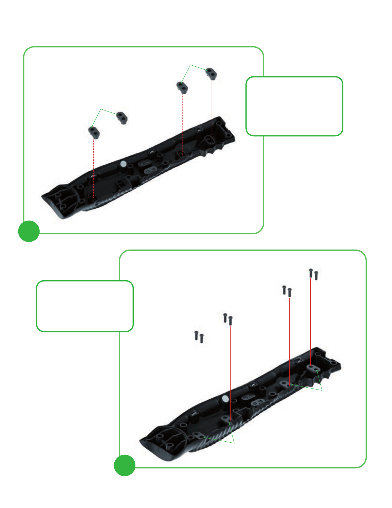
KIT 21
THE RIGHT LEG (III)
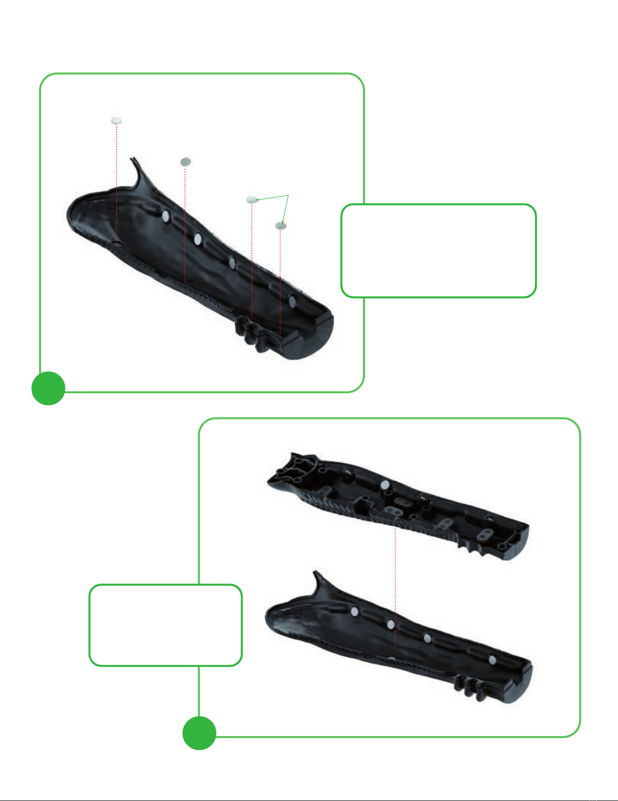
KIT 22
THE RIGHT RIBS AND
THE LEG (II)
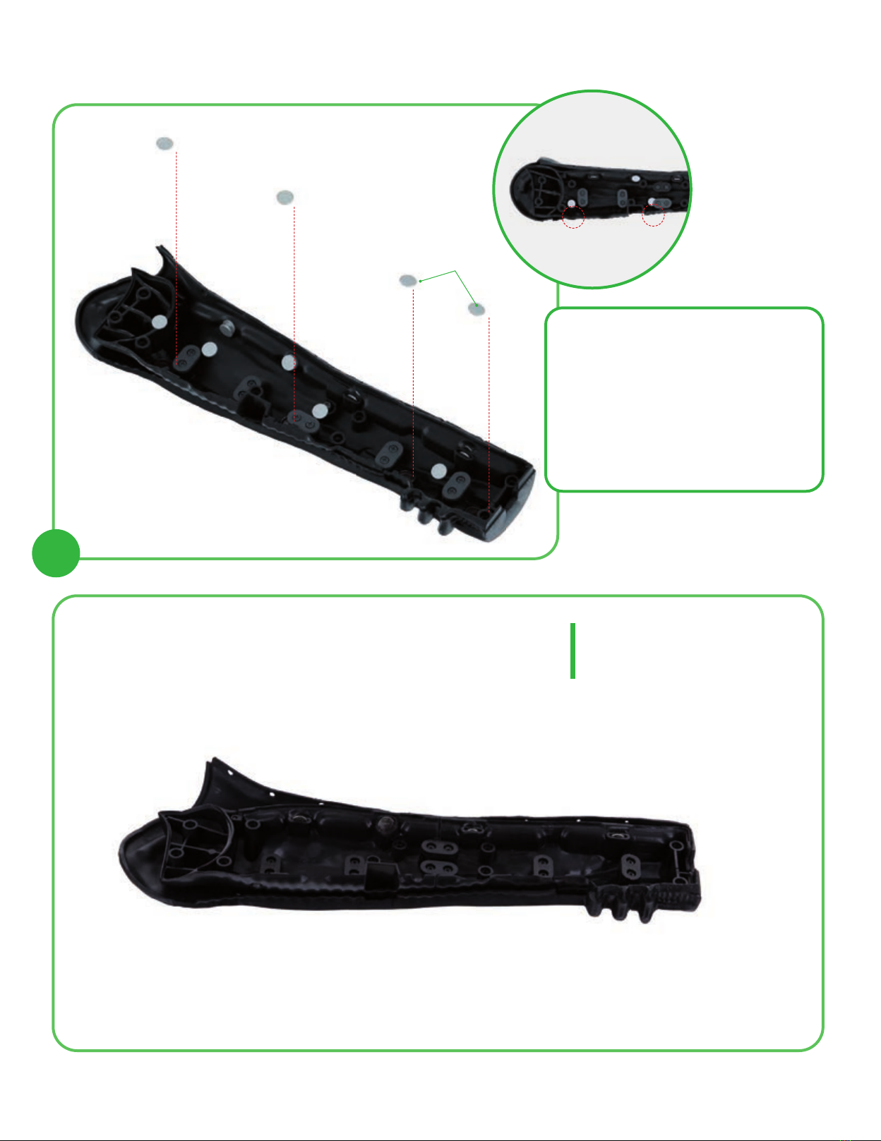
KIT 23
THE RIGHT RIBS AND
THE LEG (III)
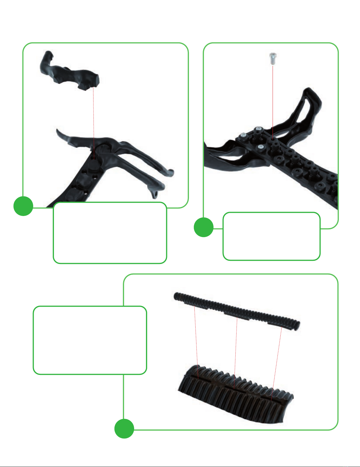
KIT 24
THE RIGHT RIBS AND
THE LEG (IV)
KIT 25
THE RIGHT RIBS AND
THE RIGHT FEMUR (I)
STEPS & TIPS ONLINE
KIT 26
THE RIGHT RIBS AND
THE RIGHT FEMUR (II)
KIT 27
THE RIGHT RIBS AND
THE RIGHT FEMUR (III)
KIT 28
THE RIGHT RIBS AND
THE RIGHT FEMUR (IV)