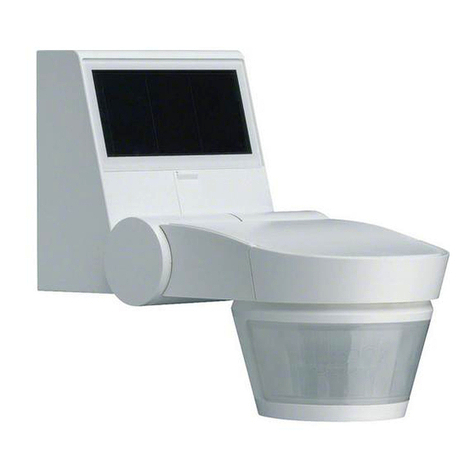
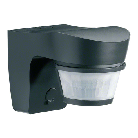
hager TRC321B User manual

TRC321B 1 6T 8085-02a
5
1. Presentation of the functions ............................................................................................................................................ 2
1.1 General points ............................................................................................................................................................. 2
1.2 Description of the product............................................................................................................................................ 2
1.3 Function Description.................................................................................................................................................... 3
2. Configuration and settings ................................................................................................................................................ 3
2.1 Objects List.................................................................................................................................................................. 3
2.2 Setting parameters ...................................................................................................................................................... 3
2.3 Configuration with media coupler (ETS version > 3.0f) ............................................................................................... 4
3. Factory reset ..................................................................................................................................................................... 6
4. Characteristics .................................................................................................................................................................. 6
Tebis application software
Luminosity detector RF quicklink
Electrical / Mechanical characteristics: see product user's instructions
Product reference Product designation Application software ref.
TRC321B Luminosity detector RF STRC321B
Summary
Loads connected
Visualisation
system
TRC321B
Shutters and blinds
control
Status indication
Media coupler
Gateway between the
RF products and the TP
products in a KNX
installation
Configuration and
parameter setting of
radio products by ETS
Transmission of radio
controls
Diagnosis
Output modules
KNX

TRC321B 2 6T 8085-02a
The luminosity detector RF this document refers to is a Quicklink RF product. It can be recognised by its cfg configuration push
button. Quicklink indicates the configuration without tools mode.
These products can also be configured to E mode by the TX100 or in S mode by ETS via the media coupler .
This document describes the configuration principle with the ETS software via the media coupler and the functions available in
this mode.
Within the same installation, a single configuration mode may be used.
To reuse a product that has already been programmed in another installation by TX100 or quicklink , with ETS, it is
necessary to perform a factory reset for the product.
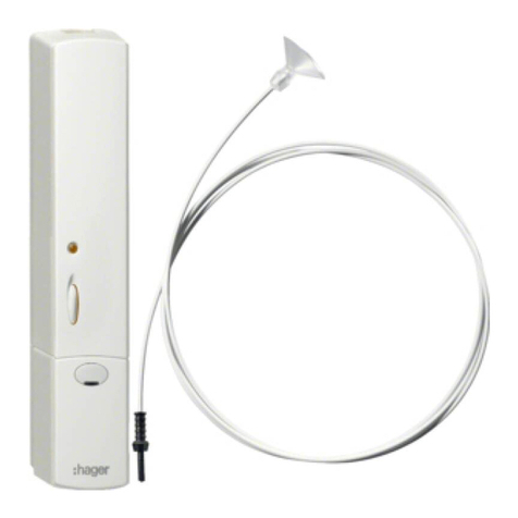
The luminosity detector is a battery-powered KNX radio transmitter. It is designed for the automatic control of shutters or blinds
(see Figure 1). According to the measured luminosity and the thresholds set on the product, it controls the raising or lowering of
the shutters and blinds to provide sun protection and/or a dusk function. Luminosity is measured sensor attached to the window
with a suction cup. The product does not transmit luminosity values.
1: Lux < threshold = Shutter up
2: Lux > threshold = Shutter descends to the level of the sensor then rises for 1 s to ensure detection again
2: Lux > threshold = Shutter up
4: Lux < threshold = Shutter fully lowered
5: Lux < threshold = No automatic raising
The KNX Up or Down controls are completely dependent:
• On the choice of the function selected on the potentiometers: sun protection (Threshold > 1500 lux) and/or dusk function
(threshold < 500 lux),
• On the configuration of the luminosity threshold(s).
These choices and settings are only accessible on the product (no parameters in ETS).
A button on the front of the product allows the user to interrupt automatic operation (no more radio transmissions except for the
Status indication - Battery status object). The effect of this button can be inhibited by configuration, leading to permanent
automatic function.
1. Presentation of the functions
1.1 General points
1.2 Description of the product
1
2
3
45
1000
2500
5000
7500
10000
OFF
LUX
10
75
150
225
300
OFF
LUX
Lux
1500 Lux
500 Lux
LUX
LUX

TRC321B 3 6T 8085-02a
Compatibility
The luminosity detector can control all the KNX shutter actuators, RF or wired, according to the automatic control function
described in figure 1.
Test function
This mode is used to run an accelerated test of your programming (see the product user manual).
Time delay
When the shutter is completely shut, the frequency at which the luminosity is measured switches to 20 mn. During the day, this
time delay changes to approximately 15 mn before a control is sent when the threshold is passed.
The luminosity detector is designed for automatic shutter control. It only offers the following 3 objects:
• Input - Up / Down,
• Input - Slat angle / Stop,
• Status indication - Battery Status.
■Input - Up / Down
The Input - Up/Down object is automatically sent according to manual settings made on thedetectors 2 potentiometers (no
parameters).
■Input - Slat angle / Stop
The Input – Slat angle / Stop object is automatically sent according to manual settings made on the detector's 2 potentiometers
(no parameters). The detector is a shutter controller, it does not cover the slant angle function. Only the stop control is used on
this object.
■Status indication - Battery Status
The status indication - battery status object is information sent on the bus when the battery charge reaches a critical level.
Information is not sent periodically. It is sent when the critical threshold is reached.
0 = Low level
1 = High level, (Batteries OK). Sent when new batteries are put in.
No parameters.
The TRC321B luminosity detector only offers one parameter.
1.3 Function Description
2. Configuration and settings
2.1 Objects List
2.2 Setting parameters
Parameter Description Value
Push button automatic
operation
This parameter defines utilization of the button on the front of the product.
• Used: allows the user by pushing the push button to interrupt automatic
operation (telegrams are no longer sent each time the opening changes
status) and by pushing the button again to re-establish automatic
operation,
• Not used: in this case, pushing the push button will no longer have any
effect (permanent automatic operation).
Not used, Used
Default value:
Used

TRC321B 4 6T 8085-02a
■Configuration principle
The media coupler enables confuguration by ETS of RF devices for a KNX radio installation or a mixed KNX installation
including RF devices and wired buses. For normal operation, the radio transmitters operate in a one-direction mode.
Configuration takes place in bi-directional mode.
Procedure:
• Create a line reserved for RF devices in your ETS plan. First insert the media coupler into this line, then insert the other
RF devices into this line,
• Perform the programming, parameter settings and group addressing for all the RF products except for the media coupler,
• Download the physical address of the media coupler. This must be of the type 1.1.0 (always end with a zero),
• Install the media coupler plug-in: Right-click on the product in the ETS tree structure, then select edit the parameters.
Windows Administrator rights are necessary to install the plug in.
■Physical addressing:
• Click on the button Physical addressing to display the physical addressing screen for the plug in,
• Select the device to be addressed, then click on the field Addressing in the menu line at the upper left of the window,
• Press the cfg button for each transmitter to be addressed, then click Device search (if the device is not found by the
search, perform a RESET device out of installation, or manually on the device by pressing the cfg > 10 s button)
• Select the device to be addressed and click on Attribute address. The physical addressing of the product is performed.
The product is now part of the installation,
• After downloading the physical address, the symbol appears in front of the product,
• Repeat this operation for the other radio transmitters.
Caution: After an interruption in the above operations greater than 10 mn, it is necessary to press the cfg button again on the
transmitter devices to be programmed.
2.3
Configuration with media coupler (ETS version
>
3.0f)
TRC321B 5 6T 8085-02a
■Downloading the program and the parameters
This operation is performed on the Download screen of the plug in.
• Click on Download and follow the instructions on the screen.
To test the functions and the KNX radio communication, return to normal use mode and wait 15 s before pressing a control button
on a transmitter.
Caution: The media coupler plug-in must be deactivated during the functional tests.
NB: For further information, please refer to the description of the media coupler application software.

TRC321B 6 6T 8085-02a
This function enables the product to be returned to its initial configuration (factory reset). After a device reset, the device can be
re-used in a new installation. A factory reset can be performed either directly on the product or by the media coupler plug-in. The
latter solution is recommended if the product is part of the installation configured by ETS, which erases the product from the
project.
• For a product which is part of the installation (known by the media coupler): In the Physical addressing menu, select
Factory reset and then follow the instructions which appear on the screen,
• For a product which is not part of the installation (unknown by the media coupler): In the menu Physical addressing, select
RESET device out of installation, then Unidirectional device with Addr. button.
It is always possible to perform the factory reset directly on the device.
Factory reset on the product:
Do a long key press (> 10 seconds) on the cfg push button, release the button when the cfg LED blinks,
Wait for the cfg LED to switch off, indicating that the factory reset has been completed.
Remark:
To reuse a product that has already been programmed in another installation by TX100 or quicklink , with ETS, it is necessary to
perform a factory reset for the product.
3. Factory reset
3.1 Factory reset by ETS via the media coupler
3.2 Factory reset on the product
4. Characteristics
Product TRC321B
Max. number of group addresses 60
Max. number of links 85

TRC321B 7 6T 8085-02a
Table of contents
Other hager Security Sensor manuals

hager
hager TX510 User manual

hager
hager WK050 User manual

hager
hager EE 804 User manual

hager
hager TCC520E Operating manual

hager
hager HX 701 User manual

hager
hager TRC301B User manual

hager
hager EE82 Series Manual

hager
hager H 400 User manual

hager
hager EE 810 Manual

hager
hager WH362508 X Series Service manual

hager
hager TG551A 3 User manual

hager
hager KNX 7524 10 03 User manual

hager
hager TRE530 User manual

hager
hager EE880 User manual

hager
hager Range H 1250 User manual

hager
hager S157-22X User manual

hager
hager 53601 User manual

hager
hager TX511 User manual

hager
hager S145-22X User manual

hager
hager EE815 User manual