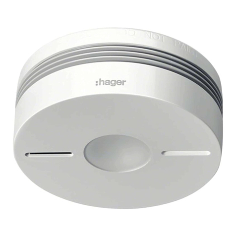
hager S157-22X User manual

3
installation manual
Heat detector, interconnectable radio,
lithium battery 10 years
S157-22X
1. Introduction
1.1. How the detector works
1.2. Description
The heat detector is designed to protect the private areas of
apartment buildings, residential properties and mobile
homes.
Heat detection is activated when:
• the rate of elevation of the ambient temperature is
abnormal,
• or the ambient temperature reaches a value between 54
and 70 ° C.
It can be:
• used alone,
• included in a hager alarm system with TwinBand®control
panel,
• interconnected in a wireless network with 40 detectors
maximum.
When something is detected, this is indicated as follows:
The detector having detected something sounds until the
smoke have disappeared.
The interconnected detectors trigger in less than one minute
and sound until the smoke detected by the activated
detector have disappeared and for a maximum period of
15 minutes.
Connected to a hager alarm system, it causes in addition:
• the triggering of the control panel and radio sirens in fire
modulation for 5 min,
• triggering the phone dialller,
• triggering wired sirens.
Detector activated Other interconnected
detectors
Rapid flashing
Emergency halo lighting
Triggering of continuous
sounding (85 dB (A) at 3 m)
Triggering of intermittent
sounding (85 dB (A) at 3 m)
Emergency halo lighting
-
Subject to the smoke detector being properly serviced on a
regular basis, it should be replaced according to the
replacement date indicated on the back of the product or
when its battery runs out.
Test utton
LED alignment arrow (gives the alignment
axis of the LEDs once the detector has
een locked on to its ase)
Red LED (alarm and programming)
Yellow LED (operation)
White LED (emergency halo lighting)
Fixing ase
Recommendations
The user must not attempt to access the detector’s internal parts, except areas described in this manual. If the user does access these parts, the product guarantee
will be considered null and void and Hager shall not be held responsible for any problems. Touching the detector’s internal parts and/or electronic components can
damage the product. Furthermore, the detector is designed in such a way that these parts and components do not need to be accessed for operation or
maintenance purposes.

4
2. Installation
The detector comes ready powered. Simply lock it on to its base (step 4. Chapter 2.2. Installing the detector as a standalone device) to
put it in normal operating mode.
• The heat detector is not intended to replace smoke or gas detectors to ensure the safety of people and especially in rooms such as
bedrooms, playroom and other places of life.
• The heat detector is suitable for fire detection where an optical smoke detector can not be used.
• For minimum fire protection, a smoke detector should be installed at least in each corridor or stairwell and in each bedroom (refer to the
S155-22X smoke detector manual, for example).
2.1. Choosing the best place to install the detector
The detector must be placed:
• in rooms where there is a fire hazard (living rooms with
fireplace, children’s bedrooms, occupied lofts or
basements, etc.) (Fig. A),
• preferably in the centre of the ceiling,
• far away from fan vents likely to spread smoke,
• more than 50 cm away from any obstacles (walls,
partitions, beams, etc.) (Fig. B),
• at each end of corridors if they are longer than 10 m.
If the detector cannot be installed horizontally on the ceiling,
fix it:
• at a distance of 40 to 50 cm from the ceiling (Fig. A),
• far away from any sources of electrical disturbance
(electricity meter, metal cabinet, electronic ballast, etc.).
The detector must not be placed:
• close to an electronic ballast, low voltage transformer,
energy saving light bulbs, fluorescent tubes, etc. (minimum
distance: 50 cm),
• in excessively dusty rooms,
• in a room where the temperature might drop below -10°C
or rise above +65°C, which would prevent the detector
from operating properly,
• at least 1 m away from heating, cooling or air circulation
vents likely to disseminate smoke or heat,
• at least 6 m away from a fireplace or wood burning stove
where the smoke from combustion might trigger an
unnecessary alarm,
• in a room where there might be condensation or damp (do
not use in bathrooms, laundries, etc.)
• at the centre of a pointed ceiling (A-shaped), as the air
pocket located here can prevent smoke from reaching the
detector (Fig. B),
• directly on to a metal wall: use a non-magnetic spacer
(wooden or plastic).
A
Recommended
location
d > 50 cm
50 cm > d > 40 cm
Accepta le
location
d > 50 cm
B
2.2. Installing the detector as a standalone device
Use the LED alignment arrow on the base in order to position the detector in the best possible manner (see Description).
Fix the base keeping in mind the precautions outlined
in the chapter entitled Choosing the best place to install
the detector. The detector can be fixed in 2 ways:
Fixing the detector on a flush-mounting box
• For Ø 60 mm boxes, use fixing holes marked 60.
• For Ø 78 mm boxes, use fixing holes marked 78.
• For Ø 85 mm boxes, use fixing holes marked 85.
• Fix the base using suitable screws.
Fixing the detector on a surface
• Place the base in the planned location and mark the
position of the 2 fixing holes with a pencil.
• Drill the holes using the right-sized diameter drill bit.
• Fix the base in place using suitable wall plugs and
screws.
1Optional locking of the detector on themounting base.
Optional locking is designed to prevent unauthorized
dismounting of the detector.
Using cutting pliers, cut out the locking slot.
2
Opening will now be possible only by
means of a flat blade screwdriver.
5
• To perform recognition programming operations, the control panel must be in installation mode.
If it is not, enter on the control panel keypad:
then
• There is no need to place the product close to the control panel for recognition programming. Indeed, it is advisable to move it away
from the control panel by at least 2 metres.
• If the detector is installed in association with a control panel with a version lower than 1.11.6, it must be placed by at least 4 meters
from this one.
Control panel in installation mode, enter on her keypad to check the version.
• It is possible to record a personalised message vocally identifying the fire detector (see Control panel installation manual § Detector
vocal identification message).
2.3. Installing the detector in association with a hager alarm system
Recognition programming allows the detector to be recognised by the control panel.
The control panel allocates a detector number following the chronological order of programming.
All the radio detector must be recognized and in radio range with the control panel.
Line the marker up with the LEDs in order to position the detector on its
base.
3
Proceed to chapter 3. Testing the detector.
5
Turn the detector clockwise until it is
completely locked. The yellow
indication LED flashes for 5 s and then
once every 10 s to indicate the detector
is operating normally.
4
Red LED/yellow LED
master code installer code
1. Perform the following learning sequence:
2. Keeping in mind the precautions outlined in the chapter entitled Choosing the best place to install the detector, position
the detector in the chosen location without fixing it in place.
3. Test the radio range with the control panel by pressing and holding down the programming key Cfg2.
• Satisfactory link: the control panel issues the voice message “Beep, test fire detector n° X” to confirm,
• nsatisfactory link: no voice message is issued. ove the detector closer to the control panel or use a radio repeater
relay.
4. Fix the detector in place following steps 1 to 4 in chapter 2.2. Installing the detector as a standalone device.
5. Put the control panel back in user mode by entering:
6. Proceed to chapter 3. Testing the detector.
Cfg
1
Cfg
2
installer code
Press *then # on the
control panel keypad.
Hold down the Cfg2 key for 10 s until the response
of the control panel.
)))))
10 s max.
then “ eep, smoke detector n°”

6
2.4. Installing the detector as part of a network
It is possible to interconnect up to 40 detectors so that all
the detectors in the home as well as the alarm system can
be triggered together.
The smoke detector can be connected with S155-22X
smoke detectors and/or S157-22X heat detectors.
The responses to detection are described in chapter 1.1.
How the detector works.
To connect the detectors in a network:
Installing detectors in a network
S157-22X radio detector
)))))))))))
)))))))))))))))
))))))))
)))))))))))))))
)))))))))))))))
Control
panel
Network
All radio detectors must
imperatively to be learned
and within reach radio
station.
Put all the detectors to be
networked in recognition
programming mode by pressing
2 times on the Cfg1 key.
The red LED flashes.
Cfg
1
Cfg
2
)))))))))))))))))))))
))))))))))))))
))))))))))))))))))))
Control
panel
Detectors
1
Press the test button on one
of the detectors until the red
LED on all the other detectors
lights up steadily. Release the
button, the red LED of this
detector flashes.
2
Lightly press on the Cfg1 key on all of the detectors
to exit recognition programming mode.
Without press on the Cfg1 key the detectors outside the
programming mode after one minute.
In this case, the networking of the detectors is taken into
account.
3
Cfg
1
Cfg
2

7
Test the radio range.
A. Put all the detectors in test mode by pressing once on the Cfg1 button. The red LED lights up for 5 sec and then
flashes.
B. Press the test button on one of the detectors and the detector will test the radio range in permanent transmission
mode. The red LED on all the other detectors lights up steadily.
C. Position the detectors in their planned locations without fixing them in place.
• If the radio range is satisfactory, the red LED remains steadily lit.
• If the radio range is not satisfactory, the red LED flashes.
D. ove the detectors located outside of the radio range or programme one detector as a relay (see 2.5. Installing the
detector as a relay) then perform the test again.
E. To exit the test mode, press once on the Cfg1 button on all the detectors. The red LED goes out.
F. Perform the radio range test for all the detectors again to make sure they trigger, whatever the detector having
activated the alarm.
4
Fix the detectors in place following steps 1 to 4 in chapter 2.2. Installing a detector as a standalone device.
5
))))))))))))))))))))))
))))))))))))))))))))))))))))))))))
))))))))))))))))))))))
))))))))))))))))))))))))))))))))))
)))))))))))))))))))))
)))))))))))))))))))))
A. If an alarm is activated on detector 1, only detector 2
and the control panel will be triggered.
B. Detector 2 is programmed as a relay. If an alarm is
activated on detector 1, the detector retransmits the
information on the whole installation.
Examples:
Detector 1
Detector 2 Radio range limit
Contol panel Detector 1 Centrale Detector 3
Detector 2 Detector 4
Specific cases
Adding a detector to an existing network
1. Put the detector to be added to the network in recognition programming mode by pressing 2 times on the Cfg1 key. The
red LED flashes.
2. Put one of detector that are already in the network in recognition programming mode by pressing 2 times on the Cfg1 key.
The red LED flashes.
3. Press the test key on a detector that is already in the network until the red LED on both detectors lights up steadily.
4. Briefly press Cfg1 on one of the detectors to exit the programming mode.
Putting a detector back into its factory configuration
Upon the back into factory configuration, the interconnection between the detectors will be deleted.
1. Press 2 times on the Cfg1 key.The red LED flashes.
2. Keep holding on the Cfg1 key until the red LED light up steadily. Release the button.
3. Briefly press Cfg1 to exit the programming mode.
If the radio range between all the detectors is insufficient, one of the detectors can be progra-med as a relay. This means
that it will re-transmit alarms received to all the other detectors.
It is possible to programme just one “relay” detector per network.
• To be programmed as a relay, the detector must first have been programmed for recognition by the network.
2.5. Installing the detector as a relay
To programme a detector as a relay:
1. Press Cfg1. After 4 s, the red LED flashes. Keep holding the button down.
2. After 10 s, the flashing speeds up or slows down:
- if the flashing speeds up, the relay function has been activated,
- if the flashing slows down, the relay function is still deactivated.
3. Release the button and press briefly on Cfg1 to exit the programming mode.

8
Press the detector test button until you hear the 2nd beep
and then release it.
Press the test button again to stop the integrated sounding.
3. Testing the detector
4. Using the detector
• The detectors must be installed before test.
• Before a smoke detector test, it is advisable to first let your
neighbours know and take the necessary precautions to
prevent hearing disorders.
• Never use a naked flame to test the detector.
• The test must be performed at least once a month and
notably after a prolonged absence.
• During these 15 minutes, the detector will not be able to recognise smoke or generate an alarm.
• To exit inhibition mode more quickly, press the detector test button. The detector beep, the red LED stop flashing.
Detector activated Other interconnected detectors
Rapid flashing
Emergency halo lighting
for 250 ms followed
by a 1.75 sec. pause
Sounding for 1 sec. (75 dB (A) at
1 m) followed by a 1 sec. pause
Sounding for 250 ms (75 dB (A)
at 1 m) followed by a 1.75 sec.
pause
Emergency halo lighting
-
Inhibited detector Other interconnected detectors
1 flash every 2 seconds -
To prevent untimely triggering due to activities likely to
generate smoke or dust (sweeping a dusty room, sweeping
a chimney, etc.), the detector can be deactivated for roughly
15 min.
To do this, press one time on the test button. The detector
beep, the red LED flash every 2 s. After 15 min or after the manual test, the detector
automatically becomes operational once more.
4.1. Inhibiting the detector
To stop the alarm if it has detected harmless smoke:
• press the test button,
or
• press one of the keys on an infrared remote control (remote control of a TV, DVD
player, hi-fi system) and point the remote control towards the sounding detector.
The detector will switch to inhibited mode (see chapter 4.1.) for 15 minutes.
Please note that the alarm can be stopped 20 s after the detector triggers the system.
If the detector is associated with a hager alarm system (see chapter 2.4.) Press the “Off” key command to stop the central
and the sirens.
4.2. Stopping the alarm in the event of non-dangerous detection
OR
If the detector is installed as a
standalone device:
• press the test button,
or
• press 2 times one of the keys on
the remote control pointed on the
detector.
Detector activated
OR
Detector activated
))))))))))))))
))))))))))))))))))
• The 1st time one of the keys on the remote
control or the detector test utton is
pressed: interconnected detectors stopped.
• The 2nd time one of the remote control keys
pointed on the detector or the test utton
of the detector having triggered the alarm is
pressed: the detector having triggered the
alarm is stopped.
If the detector is part of a network:
The detector(s) having been activated (red LED flashing) must be stopped to
end network sounding.

9
When you replace the detector, you must also replace its mounting base.
Detector at the source
of the fault indication Other interconnected detectors
2 flashes every 5 sec.
2 rapid beeps every 60 sec. 2 rapid beeps every 60 sec.
1 flash every 10 seconds
5. Maintenance
5.1. Replacing the detector
The detector must not be painted.
If work is to be carried out after the detector has been
installed, cover it completely..
5.2. In case of work in the home
In order not to wake you up, alarms resulting from mains supply problems or dirty sensors are shut down during the night.
Any errors are corrected after daybreak within 10 minutes i.e. 8 hours after the event.
4.3.1. Power fault
4.3. Fault indications
If the audible power fault indication occurs at an inconvenient time, it can be postponed for 8 hours over a maximum
duration of 7 days by pressing the test button until you hear the first beep.
If the detector is associated with a control panel, the panel provides vocal notification following a system command: “Beep,
power fault, detector n° X”.
4.3.2. Detection head faulty or dirty
If the audible power fault indication occurs at an inconvenient time, it can be postponed for 8 hours over a maximum
duration of 7 days by pressing the test button until you hear the first beep.
Detector at the source
of the fault indication Other interconnected detectors
8 flashes every 8 sec.
8 rapid beeps every 60 sec. 8 rapid beeps every 60 sec.
1 flash every 10 seconds
When the supply anomaly appears, the detector continues to
work perfectly for 30 days. It is advisable to replace the
detector as soon as possible.
If sounding continues after a postponement attempt, this
means that the detection head is not working. Replace the
detector.
Do not forget to remove the protection when the work is
finished.
1. If the detector is replaced because of a battery or detection head fault, press on the test button until it beeps to clear the
fault.
2. If the detector was associated with an alarm system:
A. Switch the control panel to installation mode by dialing on its keypad:
then
B. Clear the detector by dialing on the keypad of the central:
3. • If detector optional locking is not activated: turn the detector anti-clockwise
to unlock it.
• If detector optional locking is activated:
A. insert a flat blade screwdriver into the slot,
B. turn the detector anti-clockwise to unlock it.
4. If the detector was associated with an alarm system, refer to the chapter
2.3. Installing the detector in association with a hager alarm system.
5. If the detector was part of a network, refer to 2.4. Installing a detector as part
of a network.
6. Position the new detector on its base by turning it clockwise until it is completely locked.
7. Test the detector (see Testing the detector).
master code
detector num er
installer code
A.
B.

10
It is imperative that you keep the documentation provided with this product throughout its life.
Waste processing of electrical and electronic devices at the end of their service life (Applicable in European Union countries and other
European countries with a waste collection system). Used on products or product packaging, this symbol indicates that the product must not
be thrown out with household waste. It must be taken to a waste collection point for electrical and electronic product recycling. When you
make sure that this product is disposed of in the most appropriate manner, you are helping to protect the environment and human health. If you
would like additional information concerning the recycling of this product, please contact your town/city council, nearest waste collection centre or
the shop where you bought the product.
Hager Security SAS hereby declares that the radioelectric equipment, reference S157-22X, complies with the requirements of the
following 2014/53/E RE-D directive.
The full text of the E declaration of conformity is available at the address: www.hager.com.
Non-binding document, may be modified without prior notice.
6. Technical data
Technical data Heat detector
Radio links TwinBand®: • 433.050 - 434.790 Hz, 10 mW max, Duty cycle: 10%
• 868 - 870 Hz, 25 mW max, Duty cycle: 0,1%
Rx: category 2
Type of detection heat detector able to detect:
• temperature rise speed
• reaching of temperatures between 54 and 70°C
Average coverage 50 m2
Use indoor
Power sealed, non-replaceable lithium battery 2 x 3 V with a 10-year battery life
Indication • detector status
• faults
Integrated sounding upon detection of 85 dB to 3 m
75 dB integrated sounding at 1 m • during testing
• during fault indications
Interconnection via radio 40 detectors max.
Operating temperature -10°C to + 65°C
Storage temperature -10°C to + 65°C
Degree of protection IP22
Dimensions (D x H) 116 mm x 49 mm
Weight 255 g
This manual suits for next models
1
Table of contents
Other hager Security Sensor manuals

hager
hager EE880 User manual

hager
hager Comfort EE87 Series User manual

hager
hager H 400 User manual

hager
hager WYT 910 User manual

hager
hager TRE53 Series User manual

hager
hager TRE530 User manual

hager
hager TRC321B User manual

hager
hager TCC521E User manual

hager
hager TRC301B User manual

hager
hager TX511 User manual

hager
hager S145-22X User manual

hager
hager TRC321B User manual

hager
hager Range H 1250 User manual

hager
hager EE815 User manual

hager
hager TG551A 3 User manual

hager
hager TX510 User manual

hager
hager WH362508 X Series Service manual

hager
hager WYW51 Q Series User manual

hager
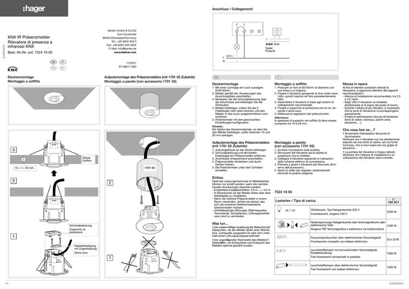
hager KNX 7524 10 03 User manual

hager
hager 53601 User manual