manuals.online logo
Brands
  1. Home
  2. •
  3. Brands
  4. •
  5. hager
  6. •
  7. Security Sensor
  8. •
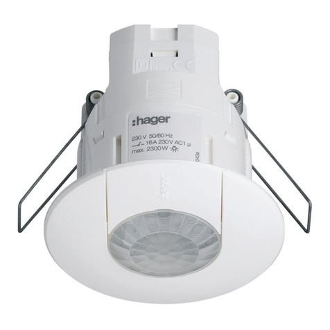
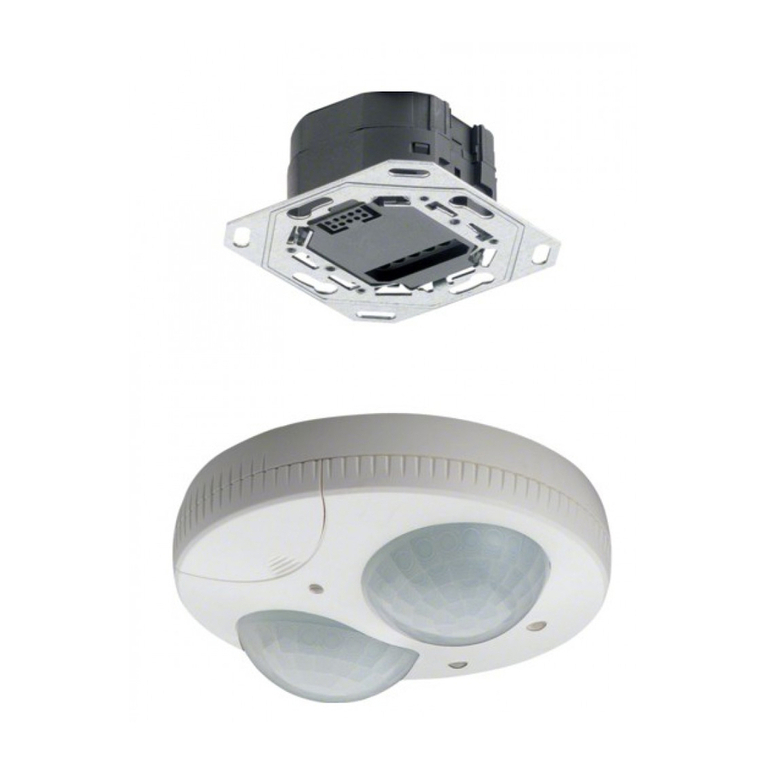
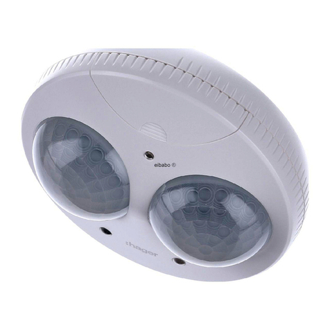
  9. hager KNX 7524 10 03 User manual

hager KNX 7524 10 03 User manual

1 6T 7980-02B
6T 7980-02B
t
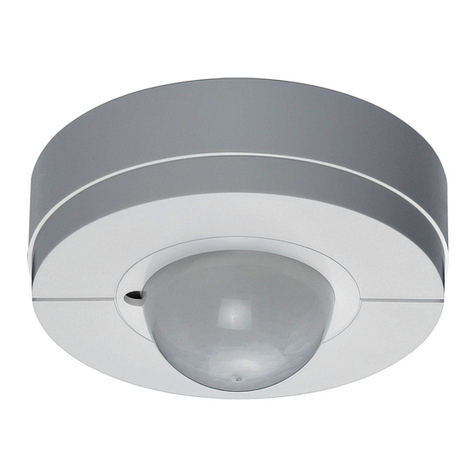
Montaggio a soffitto
1. Praticare un foro di 60-63mm di diametro con
una fresa o un trapano.
2. Fissare il rilevatore spingendo le due molle verso
l'alto, quindi inserirlo nel foro precedentemente
fatto.
3. Assemblare il rilevatore in base agli schemi di
collegamento raccomandati.
4. Fissare il coperchio di protezione con le viti, fis-
sando il serra cavo.
5. Effettuare le regolazioni dei potenziometri.
Attenzione :
lo spessore di supporto nel soffitto (t) deve essere
compreso tra 10 e 28 mm.
Montaggio a parete
(con accessorio 1701 05)
1. Avvitare l'accessorio sulla scatola;
2. Rimuovere dal rilevatore sia la calotta di
protezione che le mollette;
3. Collegare il rilevatore seguendo le indicazioni
dello schema elettrico di connessione;
4. Premere e girare il rilevatore per bloccarlo all'in-
terno dell'accessorio;
5. Aprire lo slider per regolare i potenziometri
secondo le proprie esigenze.
Deckenmontage
1. Mit einer Lochsäge ein Loch aussägen
Ø 60-63mm.
2. Melder gemäß den Anweisungen des
Anschlussbildes anschließen.
3. Montieren Sie die Schutzabdeckung über
die Anschlüsse und befestigen Sie die
Schrauben.
4. Melder befestigen, indem Sie die 2
Federbügel nach oben drücken und den
Melder in das zuvor ausgeschnittene Loch
einführen.
5. Potentiometer mit den gewünschten
Einstellungen konfigurieren.
Hinweis :
Die Stärke des Deckenmaterials, an dem Sie
den Melder befestigen, sollte zwischen 10 und
28 mm betragen.
Aufputzmontage des Präsenzmelders
(mit 1701 05 Zubehör)
1. Aufputzgehäuse an der Decke befestigen
2. Schutzabdeckung und die beiden
Federbügel am Präsenzmelder entfernen.
3. Anschlüsse entsprechend anschließen.
4. Präsenzmelder einstecken und durch
Drehen fixieren.
5. Die Potentiometer unter dem Schieber
einstellen.
Einbau
Optimale Leistungsmerkmale im Meldebetrieb
können nur erzielt werden, wenn die nachste-
henden Anweisungen beachtet werden:
- Empfohlene Installationshöhe : 2.5 m —> 3.5 m
- In Büroräumen ist der Melder direkt über dem
Arbeitsplatz zu installieren.
- Wenn sie mehrere Präsenzmelder in einem
Raum verwenden, achten sie darauf, das
sich die einzelnen Detektionsbereiche
überschneiden müssen.
- Umfeldbedingte Störungen (Wärmequellen,
Trennwände, Grünpflanzen, Lüftungsaustritte
usw.) sind zu vermeiden.
Was tun…
• bei unplanmäßiger Auslösung der Beleuchtung?
Überprüfen, ob der Melder direkt einer Wärme-
bzw. Lichtquelle ausgesetzt ist oder sich unter-
halb eines Lüftungsauslasses befindet.
• bei ungenu�gender Reichweite des Melders?
Überpru�fen, ob Einbauhöhe und Einbauort des
Melders optimal gewählt wurden.
D IT
Decke
Soffitto
Schutzabdeckung
Coperchio di
protezione
Kabelbefestigung
mit Zugentlastung
Serra cavo
10 < t < 28 mm
1
2
3
Lastarten / Tipo di carica L’
16A AC1
Glühlampen, Typ Halogenleuchte 230 V
Incandescenti, alogene 230 V 2300 W
Niederspannungs-Halogenleuchte über ferromagnetische oder
elektronische Trafo
Alogena TBT ferromagnetica o elettronica via trasformatore
1500 W
Fluocompactleuchten über elektronisches Vorschaltgerät
Fluorescente compatto con ballast elettronico 23 x 23 W
Leuchtstofflampen mit konventionellen Vorschaltgerät,
Parallelschaltung
Tubi fluorescenti compensati in parallelo
1000 W
Leuchtstofflampen über elektronisches Vorschaltgerät
Tubi fluorescenti con ballast elettronico 1000 W
7524 10 03
Best.-Nr./Nr. ord. 7524 10 03
Montageanleitung
Istruzioni di montaggio
KNX IR Präsenzmelder
Rilevatore di presenza a
infrarossi KNX
Berker GmbH & Co. KG
Klagebach 38
58579 Schalksmühle/Germany
Telefon: + 49 (0) 23 55/90 5-0
Telefax: + 49 (0) 23 55/90 5-111
www.berker.com
06/2012
97-09917-000
Anschluss / Collegamenti
N
L’ L
Remote push button
Remote load
L
230 V
bus
Taster
Pulsanti
Æ
§
¶
D
1
2
Aufputzmontage des Präsenzmelders (mit 1701 05 Zubehör)
Montaggio a parete (con accessorio 1701 05)
1701 05
Deckenmontage
Montaggio a soffitto Messa in opera
Al fine di ottenere condizioni ottimali di
rilevazione, è opportuno attenersi alle seguenti
raccomandazioni :
- Altezza di installazione raccomandata: tra 2,5
e 3,5 metri.
- Negli uffici il rilevatore va installato
direttamente al di sopra del posto di lavoro.
- Durante l'utilizzo di più rilevatori, è necessario
che le zone di rilevazione si sovrappongano
parzialmente.
- Evitare le perturbazioni dovute all'ambiente
(fonti di calore, tramezzi, piante verdi,
aerazione, ...).
Che cosa fare se…?
• Avviamento intempestivo del punto di
illuminazione :
Verificare che il rilevatore non sia direttamente
esposto ad una fonte di calore, ad una fonte
luminosa, che si trovi sopra ad una griglia di
aerazione…
• La portata del rilevatore è troppo debole :
Verificare che l'altezza di installazione e la
collocazione del rilevatore siano corrette.
01 6LE005452A
e y
z m
6LE005452A
Berker GmbH & Co.KG
Zum Gunterstal
66440 Blieskastel/Germany
Tel.: +49 6842 945 0
Fax: +49 6842 945 4625
E-Mail: info@berker.de
www.berker.com
11/2021
97-09917-000
E Ye y
2
6T 7980-02B
t
Montaż sufitowy
1. Za pomocą piły otwornicowej wyciąć otwór o
średnicy 60-63 mm.
2. Zamontować detektor poprzez skierowanie ku
górze obu sprężyn i wprowadzenie ich do
otworu.
3. Podłączyć detektor zgodnie z zaleceniami
zawartymi w schemacie połączeń.
4. Zamocować osłonę zacisków i przykręcić zacisk
przewodu.
5. Ustawić potencjometry zgodnie z pożądanymi
wartościami.
Uwaga :
Grubość sufitu (t) musi zawierać się w zakresie od
10 do 28 mm.
Mocowanie zewnętrzne
(z elementem dodatkowym 1701 05)
1. Przykręcić element do puszki podtynkowej
montażowej.
2. Usunąć spężyny z detektora.
3. Podłączyć przewody do detektora zgodnie z
zaleceniami zawartymi w schemacie połączeń.
4. Wcisnąć i obrócić detektor dla zblokowania w
elemencie dodatkowym.
5. Otworzyć klapkę i ustawić potencjometry
zgodnie z pożądanymi wartościami.
Ceiling mounting
1. Cut out a 60-63 mm diameter hole using a
hole saw.
2. Fix the detector by pushing both springs
upward then insert them into the hole.
3. Wire the detector according to the
recommended connection diagram.
4. Mount the protective cover over the
terminals and screw the cable clamp.
5. Set potentiometers according to the
desired values.
Note :
The thickness of the support ceiling (t) must be
within 10 to 28 mm range.
Surface mounting
(with accessory 1701 05)
1. Screw the accessory on the flush mounting
box.
2. Remove the protective cover and the
springs from the detector.
3. Wire the detector according to the
recommended connection diagram.
4. Push and turn the detector to lock it into
the accessory.
5. Open the slider to set the potentiometers
according to the desired values.
Implementation requirements
Requirements for optimal detection:
- Recommended installation distance from
ground : 2.5 m —> 3.5 m
- In offices, the detector must be installed
above the workstation.
- When using several detectors, detection
areas shall overlap.
- Keep away from environmental disturbances
(heat sources, partitions, houseplants,
ventilation,...).
Trouble shooting
• False switching of lighting point :
Check that the detector is not exposed directly
to a heat source or a lighting source, or is not
placed above a ventilation grid...
• The range of the detector is too short :
Check whether the distance of the device from
the ground is sufficient and its location is
optimal.
GB PL
Ceiling
Sufit
Protective cover
Osłona
Cable clamp
Zacisk przewodu
10 < t < 28 mm
1
2
3
Lighting loads / Obciążenia L’
16A AC1
Incandescent, Halogen 230 V
Żarowe, Halogen 230 V 2300 W
Halogen VLV via ferromagnetic or electronic transformer
Halogen VLV poprzez transformator ferromagnetyczny lub
elektroniczny
1500 W
Fluocompact with electronic ballasts
Fluocompact ze statecznikiem elektronicznym 23 x 23 W
Parallel compensated fluorescent tubes
Podłączenie równoległe jarzeniówek 1000 W
Fluorescent via electronicballasts
Fluorescjencja poprzez stateczniki elektroniczne 1000 W
7524 10 03
OCOM 114155
Order no./Nr zamówieniowy
7524 10 03
Installation instructions
Instrukcja montażu
KNX IR presence detector
Czujnik obecnosci IR KNX
Berker GmbH & Co. KG
Klagebach 38
58579 Schalksmühle/Germany
Telefon: + 49 (0) 23 55/90 5-0
Telefax: + 49 (0) 23 55/90 5-111
www.berker.com
06/2012
97-09917-000
Connection / Podłączenie
N
L’ L
Remote push button
Remote load
L
230 V
bus
Remote push button
Przycisk zdalny
Æ
§
¶
D
1
2
Surface mounting (with accessory 1701 05)
Mocowanie zewnętrzne (z elementem dodatkowym 1701 05)
1701 05
Ceiling mounting
Mocowanie sufitowe Wymagania dotyczące wykonania
Wymagania dla optymalnej detekcji:
- Zalecany odległość montażu od ziemi :
2,5 m —> 3,5 m
- W biurach detektor musi być zamontowany
nad stacjami roboczymi.
- Przy użyciu kilku detektorów, obszary
detekcji powinny na siebie nachodzić.
- Trzymać z dala od zakłóceń środowiskowych
(źródeł ciepła, przegród, roślin doniczkowych,
wentylacji,...).
Usuwanie problemów
• Błędne włączanie punktu świetlnego :
Sprawdzić czy detektor nie jest wystawiony na
bezpośrednie działanie źródła ciepła lub
światła, lub czy nie jest umieszczony nad
siecią wentylacyjną...
• Zasięg detektora jest za mały :
Sprawdzić czy odległość urządzenia od ziemi
jest wystarczająca i lokalizacja optymalna.
• Przy niskim poziomie jasności podczas regu-
lacji światło może migać:
sprawdzić zakres ściemniania zastosowanych
stateczników żarówek; korzystać z urządzeń
pracujących w zakresie 1 – 100%.
6T 7980-02B
02 6LE005452A
e y
z m
6LE005452A
Berker GmbH & Co.KG
Zum Gunterstal
66440 Blieskastel/Germany
Tel.: +49 6842 945 0
Fax: +49 6842 945 4625
E-Mail: info@berker.de
www.berker.com
11/2021
97-09917-000
MZ m
z

Other hager Security Sensor manuals

hager TRC321B User manual

hager

hager TRC321B User manual

hager TRC301B User manual

hager

hager TRC301B User manual

hager EE815 User manual

hager

hager EE815 User manual

hager WYW51 Q Series User manual

hager

hager WYW51 Q Series User manual

hager TRE530 User manual

hager

hager TRE530 User manual

hager EE 804 User manual

hager

hager EE 804 User manual

hager EE 810 Manual

hager

hager EE 810 Manual

hager WH362508 X Series Service manual

hager

hager WH362508 X Series Service manual

hager TRC321B User manual

hager

hager TRC321B User manual

hager TX510 User manual

hager

hager TX510 User manual

hager WK050 User manual

hager

hager WK050 User manual

hager EE883 User manual

hager

hager EE883 User manual

hager WE050 User manual

hager

hager WE050 User manual

hager TCC510S User manual

hager

hager TCC510S User manual

hager EE82 Series Manual

hager

hager EE82 Series Manual

hager WYT 910 User manual

hager

hager WYT 910 User manual

hager Comfort EE87 Series User manual

hager

hager Comfort EE87 Series User manual

hager TX510 Manual

hager

hager TX510 Manual

hager Range H 1250 User manual

hager

hager Range H 1250 User manual

hager TRC301B User manual

hager

hager TRC301B User manual

hager EE880 User manual

hager

hager EE880 User manual

hager S145-22X User manual

hager

hager S145-22X User manual

hager 53601 User manual

hager

hager 53601 User manual

hager TCC521E User manual

hager

hager TCC521E User manual

Popular Security Sensor manuals by other brands

Teletek electronics SensoIRIS S130 installation instructions

Teletek electronics

Teletek electronics SensoIRIS S130 installation instructions

SECO-LARM SLI Enforcer E-964-D390Q manual

SECO-LARM

SECO-LARM SLI Enforcer E-964-D390Q manual

Nice HSDIM24 Instructions and warnings for installation and use

Nice

Nice HSDIM24 Instructions and warnings for installation and use

Samcon ExCam XPT Q6055 user manual

Samcon

Samcon ExCam XPT Q6055 user manual

ParTech 715 Operator's manual

ParTech

ParTech 715 Operator's manual

Bacharach H-10 PRO How to Clean

Bacharach

Bacharach H-10 PRO How to Clean

ETI SCNP-OCC Use and care guide

ETI

ETI SCNP-OCC Use and care guide

LEGRAND CP Electronics Casambi EBDMR-CB-DD installation guide

LEGRAND

LEGRAND CP Electronics Casambi EBDMR-CB-DD installation guide

Elkron VSD3 installation manual

Elkron

Elkron VSD3 installation manual

Grasslin talis PFDR 360-8-1 operating manual

Grasslin

Grasslin talis PFDR 360-8-1 operating manual

Desa JOURNEYMAN HD-9240 manual

Desa

Desa JOURNEYMAN HD-9240 manual

Vallen ISAFE3 Series Operation manual

Vallen

Vallen ISAFE3 Series Operation manual

NA-DE 00777 quick start guide

NA-DE

NA-DE 00777 quick start guide

Rielta FOTON-SH2-RK installation guide

Rielta

Rielta FOTON-SH2-RK installation guide

THORLABS PDA8A2 quick reference

THORLABS

THORLABS PDA8A2 quick reference

Vega VEGATRENN 149A EX operating instructions

Vega

Vega VEGATRENN 149A EX operating instructions

Viscotek TDA 302 Instrument manual

Viscotek

Viscotek TDA 302 Instrument manual

Inovonics EE1261 installation instructions

Inovonics

Inovonics EE1261 installation instructions

manuals.online logo
manuals.online logoBrands
  • About & Mission
  • Contact us
  • Privacy Policy
  • Terms and Conditions

Copyright 2025 Manuals.Online. All Rights Reserved.