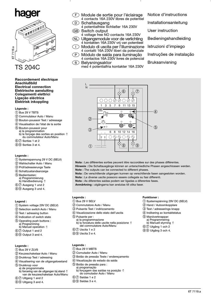
hager WHT390 User manual

01
6LE008065C
eFunk-Ttaster 2-, 4-, 6fach KNX
mit Batterie kallysto
aMécanisme 2, 4, 6 entrées KNX
radio à pile kallysto
yPulsante 2, 4, 6 tasto radio KNX con
batteria kallysto
zRadio push-button 2, 4, 6gang KNX
with battery kallysto
AI1_EV108_T4_04.eps
100%
50%
WHT390
WHT920. WHT940. WHT960.
bN,;/
TX100
1-5,2-6
1,2,5,6
1 6
2x
6x
WHT390
12
34
56
6T0864a
ECH 80%
1
2
S
4x
3
3
1
2
TX100
1-5,2-6
1,2,5,6
1 6
2x
4x
6x
WHT390
12
34
56
6T0864a
WH2092020.Z
5
WH2092020.Z
5
WHT390
7
WHT390
7
WHT9...
8
WHT9...
8
WHT99..
6
WHT99..
6
WHT0999
4
4*
WH109902E WHT0998
5*
1
4
6
2
5
3
WHT390 tebis

02
Ech. 30 %
Ech. 50 %
ech 50%
ech 30%
e
Achtung:
- Einbau und Montage dürfen nur durch
eine Elektrofachkraft erfolgen.
- Dieses Gerät nicht im Aussenbereich
einbauen.
- Installationsvorschriften zur
Schutzmassnahme SELV beachten.
Produktbeschreibung (Bilder 4, 5 und 6)
1
Taster 1 bis 6
2
Wählschalter
3
Status-LED
4
Grundplatte
4*
Befestigungsplatte
5
Rahmen
5*
Zwischenplatte
6
Frontrahmen
7
AP-Einsatz
8
Tasterfront
Der Taster WHT390 ist ein Sender, der zur Steuerung
der tebis-Ausgangsmod
u
le dient. Dieses Gerät
gehört zum KNX tebis Installationssystem. Er sendet
Schaltbefehle fur Beleuchtung, Heizung, Rollläden
und Szenen über den KNX-Funk Bus.
Das Gerät
kommuniziert über Funkfrequenzen im Simplex-
Modus.
Der Taster passt zu den Abdeckblenden
WHT920., WHT940. oder WHT960. und zu den
kallysto Rahmen.
Funktionen
- 2, 4 oder 6 voneinander unabhängige Eingänge:
ein manueller Wählschalter an der Gerätefront
ermöglicht die Auswahl des benutzten Tasters
(2-, 4- oder 6fach).
-Stromversorgung : durch Batterie versorgt.
- Ein Etikettenhalter dient zur Beschriftung der
angesteuerten Kreise (im Lieferumfang der
Abdeckblende enthalten).
-
Status-LED
3für Funksendebetrieb und
“Batterieladung schwach” Anzeige.
Einstellungen
Die Position des Wählschalters ist vor Beginn des
Einlesens einzustellen.
Taster Tasterfront aktive Taster
2fach Taste 1
/
2 1 und 5 / 2 und 6
4fach Taste 1
/
2 und 3
/
4 1
/
2 und 5
/
6
6fach Taste 1
/
2
/
3
/
4
/
5
/
6 1
/
2
/
...
6 (alle)
- Konfiguration im E-mode (via TX100):
�
Wählschalter mit Schraubendreher je nach
gewählter Anzahl der Eingänge auf 2-, 4- oder
6fach einstellen,
�
Verwenden Sie dazu TX100 V.1.9 oder höher:
Ausführliche Beschreibung in der mit dem
Konfigurationsgerät mitgelieferten Bedienungs-
anleitung.
Montage
3 Montagearten nach Wahl:
-Clip-Befestigung am Befestigungsbugel 4* und
Fixierung mittels Schrauben in einer Standard-
Unterputzdose (Bild 6).
- Montage in AP-Gehäuse (54 mm, WH21…00Q)
bzw. flaches Modell (39 mm, WH21…00N).
- Die Grundplatte
4
mit
mitgeliefertem
Doppelklebeband auf eine ebene Fläche
kleben (Bild 8) oder mit 4 Schrauben auf einer
Wand befestigen (Bild 7).
Die Montage auf einer Metallwand kann die
Produktleistungen verschlechtern.
Der Taster AP-Einsatz kann je nach Anwendung
horizontal oder vertikal
montiert werden.
Zur Demontage wird ein Schraubendreher in die
dafür vorgesehenen Aussparungen am Einsatz
eingeführt.
Montage in Mehrfach-Rahmen
2 Montagearten nach Wahl:
- Nur Funk-Geräte:
Eine der Befestigungsplatten entlang der
Sollbruchstelle (Bild 9) durchtrennen.
- Funk- und verdrahtete Geräte:
Befestigungsplatte des Funk-Gerätes entlang
der Sollbruchstelle (Bild 10) durchtrennen.
Funktionen der Status-LED
Die Status-LED
3
leuchtet kurz nach Betätigung
einer der Tasten:
- Kurzes Aufleuchten: der Befehl wurde gesendet.
- Blinkt 1 Sek.: das Gerät ist nicht konfiguriert.
- Blinkt schnell 2 Sek. oder kein Aufleuchten:
Batterieladezustand schwach, die Batterie muss
schnellstmöglich ausgewechselt werden.
Batterie auswechseln (Bild 11)
Leere Batterien nur durch identischen
oder gleichwertigen Typ ersetzen. Vor der
Entsorgung Kontaktflächen abkleben.
ATasterfront mit einem Schraubendreher
demontieren.
BAP-Einsatz mit einem Schraubendreher lösen.
CBatterie entfernen und neue Batterie einlegen
(Polaritätssymbole beachten).
DAP-Einsatz festschrauben.
ETasterfront wieder befestigen.
Technische Daten
Versorgungsspannung: 1x CR 2430 3,0 V
Lebensdauer der Batterie: 1 Jahr bei maximal 10
Aktivierungen pro Tag
Sendefrequenz: 868,3 MHz
Sendeleistung: 25 mW
Empfängerkategorie: 2
KNX Konfigurations-Modus: ETS via Medien-
koppler
Übertragungs-Modus: KNX RF1.R
Abmessungen L x B x H: 45 x 45 x 7 mm
Schutzart: IP 20
Betriebstemperatur: 0 °C —> + 45 °C
Lagertemperatur: -20 °C —> + 70 °C
Leere Batterien sofort entfernen und
umweltgerecht entsorgen. Batterien nicht
in den Hausmüll werfen. Auskunft über
umweltgerechte Entsorgung gibt die
kommunale Behörde. Gemäß gesetzlichter
Vorgaben ist der Endverbraucher zur Rückgabe
gebrauchter Batterien verpflichtet.
Vereinfachte EU-Konformitätserklärung:
Hiermit erklärt Hager Industrie AG, dass der Funk-
anlagentyp Funk-Taster 2-, 4-, 6fach KNX der Richtlinie
2014/53/EU entspricht. Der vollständige Text der
EU-Konformitätserklärung ist unter der folgenden
Internetadresse verfügbar: hager.com.
7
8
9
10
11
WHT3....
7
7
7
4
4
4
4
4

03 Hager Industrie AG, Sedelstrasse 2, 6020 Emmenbrücke, Switzerland
a
Attention :
- Appareil à installer uniquement par un
installateur électricien.
- Ne pas installer ce module à l’extérieur
du bâtiment.
- Respecter les règles d’installation TBTS.
Présentation du produit (images 4, 5 et 6)
1
Boutons-poussoirs 1 à 6
2
Sélecteur
3
LED d'état
4 Plaque de fixation
4*Etrier de fixation
5 Plaque de recouvrement
5*Support plastique
6 Intercadre
7 Mécanisme
8 Touches
Le mécanisme WHT390 est un émetteur universel
qui permet de piloter des modules de sortie tebis.
Il fait partie du système tebis. Il permet de
transmettre, via radio EIB/KNX, des commandes
d’éclairage, chauffage, volets et scènes.
Ce produit communique par radio fréquence en
unidirectionnel. Ce mécanisme s’utilise avec les
touches WHT920., WHT940., WHT960. et s’associe
aux plaques de recouvrement kallysto.
Fonctions
- 2, 4 ou 6 entrées indépendantes.
Le sélecteur manuel situé en face avant du
produit permet de choisir le nombre de boutons
fonctionnels (2, 4 ou 6).
- Alimentation par pile.
- Porte étiquette pour repérer les circuits
commandés.
- LED d'état
3pour mode émetteur radio et
affichage "Charge de batterie faible".
Configuration
Il est nécessaire de choisir la position du sélecteur
avant la configuration.
Bouton-
poussoir
Face frontale du
poussoir
Poussoirs
actifs
2 postes Touche
1 / 2
1 et 5 / 2 et 6
4 postes Touche
1 / 2 et 3 / 4
1
/
2 et 5
/
6
6 postes Touche
1
/
2
/
3
/
4
/
5
/
6
1
/
2
/
...
6 (tous)
- Configuration E-mode (via TX100):
�
placer le sélecteur à l'aide d'un tournevis sur
2x, 4x ou 6x selon le nombre d'entrées choisi,
�
utiliser le TX100 V.1.9.0 ou supérieure :
description détaillée dans la notice livrée avec
le configurateur.
Montage
3 types de montage sont possibles :
- clipsé dans l'étrier de fixation 4* puis par vis
sur une boite d'encastrement standard (image 6).
- sur un boîtier apparent haut (54 mm, WH21....00Q)
ou bas (39 mm, WH21....00N).
- Coller la plaque de fond
4sur une surface plane
à l'aide de la bande adhésive double (image 8)
ou la fixer au mur à l'aide de 4 vis (image 7).
Le montage sur une cloison métallique peut
dégrader les performances du produit.
Le mécanisme peut être monté horizontalement ou
verticalement selon les applications commandées.
Le démontage du mécanisme s’effectue en
insérant un tournevis dans les languettes prévues
à cet effet.
Montage en combinaison
2 types de montage sont possibles :
- uniquement des produits radio :
il suffit de casser la partie sécable d'une des
plaques de fixation (image 9)
- produit radio et produit filaire :
il suffit de casser la partie sécable de la plaque
de fixation du produit radio (image 10).
Fonctions de la LED d’état
La LED d’état 3s'allume brièvement après
actionnement des touches :
- Par un allumage bref que l’ordre a été pris en
compte.
- Par un clignotement pendant 1s qu’il n’est pas
configuré.
- Avec un clignotement rapide pendant 2 s ou
aucun allumage : l'ordre est pris en compte mais
le niveau de la pile est faible, il est nécessaire de
la changer au plus vite.
Changement de la pile (image 11)
Remplacer les piles vides uniquement
par des piles de type identique ou
équivalent. Avant l'élimination, recouvrir
les surfaces de contact d'un ruban
adhésif.
ADémonter les touches à l’aide d’un tournevis,
B Dévisser le mécanisme à l’aide d’un tournevis.
C Retirer la pile, puis insérer la nouvelle pile en
respectant la polarité.
D Visser le mécanisme.
E Monter les touches et le verre.
Caractéristiques techniques
Alimentation: 1x CR 2430 3,0 V
Durée de vie approximative de la pile: 1 an avec
10 activations par jour maximum
Fréquence d'émission: 868,3 MHz
Puissance d'émission radio: 25 mW
Catégorie du récepteur: 2
KNX mode de configuration: ETS via coupleur
de médias
Mode de transmission: KNX RF1.R
Dimensions L x l x h: 45 x 45 x 7 mm
Indice de protection: IP 20
Température de fonctionnement: 0 °C —> + 45 °C
Température de stockage: -20 °C —> + 70 °C
Retirer immédiatement les piles vides et les
éliminer dans le respect de l'environnement.
Ne pas jeter les piles dans les ordures
ménagères. Les autorités communales
vous fourniront des informations concernant
l'élimination dans le respect de l'environnement.
Conformément aux prescriptions légales,
l'utilisateur est tenu de déposer les piles usagées
dans un lieu de collecte.
Déclaration UE de conformité simplifiée:
Le soussigné, Hager Industrie AG, déclare que l'équi-
pement radioélectrique du type Mécanisme 2, 4, 6
entrées KNX radio est conforme à la directive
2014/53/UE. Le texte complet de la déclaration UE de
conformité est disponible à l'adresse internet suivante:
hager.com.
y
Attenzione :
- L’apparecchio deve essere installato
unicamente da un installatore qualificato.
- Non installare questo prodotto in esterno.
- Rispettare le regole d’installazione SELV.
Presentazione del prodotto (figura 4, 5 e 6)
1 Pulsanti 1 a 6
2 Selettore
3 LED di stato
4 Piastre di fissaggio
4*Anello di montaggio con placca
5 Targa di recupero
5*Piastre di plastica
6 Struttura
7 Meccanismo
8 Copertura
I
l pulsante WHT390 ê un emettitore che permette
di pilotare i moduli d’uscita tebis. Essi fanno parte
del sistema d’installazione tebis. Esse transmette,
via il bus KNX/EIB, comandi d’illu-minazione,
riscaldamento, persiane e scene. Questo prodotto
comunica via radio unidirezionale. Questo
pulsante si utilizza con le coperture WHT920.,
WHT940., WHT960. e si impiega con le placche
decorative kallysto.
Funzioni
- 2, 4 o 6 entrate indipendenti : il selettore manuale
posto sulla faccia anteriore del prodotto permette
di scegliere il numero di bottoni funzionali.
- Alimentazione mediante pile.
- Un portaetichette permette di reperire i circuiti
azionati.
- LED di stato 3per esercizio di trasmissione radio
e indicazione "Livello basso batteria".
Configurazione
E’ necessario scegliere la posizione del selettore
prima della configurazione.
Pulsante Pulsantiera Pulsanti attivi
2 doppio Pulsante
1
/
2
1 e 5 / 2 e 6
4 doppio Pulsante
1
/
2 e 3
/
4
1
/
2 e 5
/
6
6 doppio Pulsante
1
/
2
/
3
/
4
/
5
/
6
1
/
2
/
...
6 (tutti)
- Con
figurazione E-modo (mediante TX100) :
� mediante un cacciavite posizionare il selettore
su 2x, 4x o 6x secondo il voluto numero
d’entrate,
� utilizzare il TX100 V.1.9 o superiore : descri-
zione particolareggiata nel libretto fornito con
il configuratore.
Montaggio
Il meccanismo si fissa :
- mediante clip nella staffa di fissaggio 4* e poi
mediante viti su un dispositivo d’incastro
standard (Figura 6).
-
su un quadro apparente alto (54 mm. WH21…00Q)
o basso (39 mm, WH21…00N).
- Fissare la piastra di base
4su una superficie
piatta utilizzando il nastro biadesivo in dotazione
(figura 8) o fissarlo a una parete utilizzando 4 viti
(figura 7).

04 T+41 41 269 90 00 info@hager.com hager.com - 10.2022
L’installazione su una parete metallica puo ridurre
le prestazioni del prodotto.
Il meccanismo può venire montato orizzontalmente
o verticalmente secondo le applicazioni azionate.
Lo smontaggio del meccanismo avviene inserendo
un cacciavite nelle apposite linguette.
Montaggio in multiposto
2 tipi di montaggio sono possibili :
- solo prodotti radio basta spezzare la parte
sezionabile di una delle piastre di fissaggio
(figura 9)
- Prodotto radio e prodotto filare basta spezzare
la parte sezionabile di una delle piastre di
fissaggio del prodotto radio (figura 10).
Funzioni dei LED die stato
Il LED di stato 3si illumina brevemente dopo
aver premuto uno dei pulsanti:
- Con un'accensione breve: l’ordine è stato preso.
- Lampeggia per 1 seconda dopo aver premuto
uno tasto: prodotto non configurato.
- Lampeggia rapidamente 2 secondi o non
d'accensione : i l’ordine è stato preso ma il
livello della pila e debole, è necessario
cambiare le pile.
Sostituzione della pila (figura 11)
Sostituire le pile esaurite soltanto con
pile di tipo identico o di uguale potenza.
Mascherare le superfici di contatto prima
dello smaltimento.
A Smontare i tasti mediante un cacciavite.
B Svitare il meccanismo mediante un cacciavite.
C Rimuovere la pila, poi inserire la nuova pila
rispettando la polarità.
D Avvitare il meccanismo.
E Montare i tasti e il vetro
Caratteristiche tecniche
Tensione di alimentazione: 1x CR 2430 3,0 V
Durata di avvicina a vita della batteria: 1 anno con
un massimo di 10 attivazioni al giorno anni
Frequenza portante: 868,3 MHz
Potenza di trasmissione: 25 mW
Categoria ricevitore: 2
KNX modalità di configurazione: ETS tramite
accoppiatore di media
Modalità di trasmissione: KNX RF1.R
Ingombro L x l x a: 45 x 45 x 7 mm
Grado di protezione: IP 20
Ta di funzionamento: 0 °C—>+ 45 °C
Ta di stoccaggio: -20 °C —> + 70 °C
Togliere immediatamente le batterie
esauste e smaltirle rispettando l'ambiente.
Non gettare le pile nella spazzatura
normale. Presso le autorità comunali sono
disponibili informazioni per il corretto
smaltimento. Secondo i provvedimenti di legge
l'utente finale è obbligato alla restituzione delle
batterie usate.
Dichiarazione di conformità UE semplificata:
Con la presente, Hager Industrie AG dichiara che il tipo
di apparecchiatura radio Pulsante 2, 4, 6 tasto radio
KNX è conforme alla Direttiva 2014/53/UE. Il testo
completo della dichiarazione di conformità UE è dispo-
nibile al seguente sito Internet: hager.com.
z
Caution:
- This device must be installed only by a
qualified electrician.
- Not to be installed outside.
- Conform to TBTS installation rules.
Product description (figure 4, 5 and 6)
1 Pushbuttons 1 to 6
2 Selector
3 Status-LED
4 Plate
4*Stirrup of fixing
5 Covering plate
5*Plastic support
6 Interframe
7 Power unit
8 Rocker
The pushbutton WHT390 is a transmitter designed
to control tebis output modules. It is part of tebis
installation system. It transmits orders for lighting,
heating, shutters and scenarios via bus KNX/EIB.
This product communicate by one-way radio
frequency. It is used in conjunction with rockers
WHT920., WHT940., WHT960. and in association
with decorative plates kallysto.
Functions
- 2, 4 or 6 independent inputs: the manual selector
located on the front side of the product makes
it possible to select the number of functional
buttons.
- Power supply by battery.
- A label holder makes it possible to mark contro
led circuits.
- Status LED 3for radio transmission operation
and "Battery charge low" display.
Configuration
The position of the selector must be chosen before
configuration.
Push-
button
Push-button
front
active
push-buttons
2gang button
1
/
2
1 and 5 / 2 and 6
4gang button
1
/
2 and 3
/
4
1
/
2 and 5
/
6
6gang button
1
/
2
/
3
/
4
/
5
/
6
1
/
2
/
...
6 (all)
-
E-mode configuration (via TX100):
� using a screwdriver, position the selector
on 2x, 4x or 6x depending on the number of
inputs chosen,
� use the TX100 V.1.9 or above:
detailed description in the instructions
delivered with the configurator.
Assembly
The mechanism is fixed:
- clipped into the fixation bracket 4* then with
screws onto a standard embeddable wall box
(figure 6).
- onto an apparent upper (54 mm, WH21…00Q)
or lower (39 mm, WH21…00N).
- Stick the base plate
4on a flat surface with the
supplied double-sided adhesive tape (figure 8) or
fix it with 4 screws on a wall (figure 7).
The installation on a metal partition can degrade
the performances of the product.
The mechanism can be mounted horizontally or
vertically depending on the applications controlled.
Disassembly of the mechanism is carried out by
inserting a screwdriver into the tabs provided.
Multi function assembly
2 types of assemble are possible:
- radio products only simply break the divisible
part of one of the fixation plates (figure 9)
- Radio product and landline product simply
break the divisible part of the fixation plate of
the radio product (figure 10).
Functions of the status LEDs
The status LED 3lights up briefly after pressing
one of the buttons:
-
By a short lighting: the order has been taken into
account.
-
By flickering for 1 second: the product is not
configured.
-
By flickering quickly for 2 seconds or no
lighting : the order has been taken into account
but the level of battery is low and it must be
replaced as soon as possible.
Changing the battery (figure 11)
Only replace empty batteries with an
identical or equivalent type. Mask off
contact surfaces before disposal.
A Remove the buttons with a screwdriver.
B Unscrew the mechanism with a screwdriver.
C Remove the battery then insert the new battery,
in compliance with the polarity.
D Screw the mechanism back.
D Replace the buttons and the glass.
Technical characteristics
Supply voltage. 1x CR 2430 3,0 V:
Battery approximate life duration: 1 year with max.
10 activations per day
Transmission frequency: 868,3 MHz
Transmission power: 25 mW
Receiver category: 2
KNX configuration mode: ETS via media coupler
Transmission mode: KNX RF1.R
Dimensions L x w x h: 45 x 45 x 7 mm
Degree of protection: IP 20
Operating temperature: 0 °C—>+ 45 °C
Storage temperature: -20 °C —> + 70 °C
Immediately remove empty batteries and
dispose of in an environmentally
acceptable manner. Do not throw away
batteries in household waste. The local
authorities provide information about
environmentally-friendly disposal. According to
statutory requirements, the end consumer is
obliged to return used batteries.
Simplified EU declaration of conformity:
Hereby, Hager Industrie AG declares that the radio
equipment type Radio push-button 2-, 4-, 6gang KNX
is in compliance with Directive 2014/53/EU. The full
text of the EU declaration of conformity is available at
the the following internet address: hager.com.
This manual suits for next models
1
Other hager Switch manuals

hager
hager HIC4 Series User manual

hager
hager TS 204B User manual

hager
hager EHN010 Quick guide

hager
hager HIC4 G Series User manual

hager
hager EE100 User manual

hager
hager Dream User manual

hager
hager SR000AO User manual

hager
hager HI460 User manual

hager
hager EMN005 User manual

hager
hager EG072 User manual

hager
hager TS 223 Installation instructions

hager
hager TX 206A User manual

hager
hager EE171 User manual

hager
hager SP 801 User manual

hager
hager EG 470 Installation instructions

hager
hager TX 025 User manual

hager
hager HIB4 M Series User manual

hager
hager HIC4 E Series User manual

hager
hager HIC4 T Series User manual

hager
hager WXF092 User manual