manuals.online logo
Brands
  1. Home
  2. •
  3. Brands
  4. •
  5. hager
  6. •
  7. Switch
  8. •
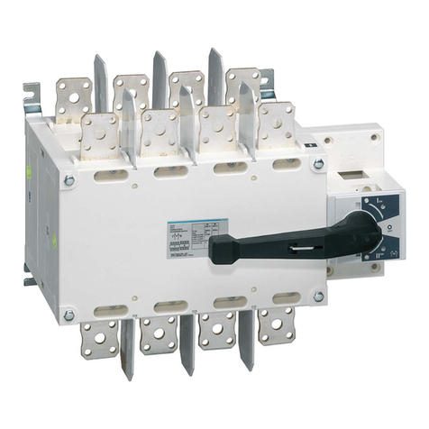
  9. hager HIC4 T Series User manual

hager HIC4 T Series User manual

6LE001768Ac1
6LE001768Ac
IS 545591C / Printing size: A3 / Recto-verso / Black / 90g/m² / Final size A4
基本操作
收到本产品并拆开包装后检查以下各项:
• 包装和内含物完好无损。
• 产品编号与订单相符。
• 内含物应包括:
- 1 HIC4xxT
- 1 个紧急手柄延长杆
- 1 套端子快速入门说明书
Preliminary operations
Check the following upon delivery and after removal of
the packaging:
• Packaging and contents are in good condition.
• The product reference corresponds to the order.
• Contents should include:
- 1 HIC4xxT
- 1 Emergency handle extension rod
- 1 Set of terminals Quick Start instruction sheet
附件
• 桥接排125 A 或160 A。
• 电压检测与电源进线并接端子。
• 端子护罩。
• 辅助触点模块。
本《快速入门》专为受过安装和调试此产品培训的人员提
供。欲了解更多详细信息,请参阅溯海格网页。
www.hager.com.
本产品必须始终由具备专业资质的人员进行安装及调试。
本产品应该由受过培训并得到授权的人员进行维修保养。
当产品内可能具有或可能将会具有直接通过电力网或间接
通过外部回路获得的电压时,请不要操作连接到产品的任
何控制或电源电缆。
始终使用合适的电压检测装置来确定无电压。
Accessories
• Bridging bars 125 A or 160 A.
• Voltage sensing and power supply tap.
• Terminal shrouds.
• Auxilliary contact blocks.
This Quick Start is intended for personnel trained in the
installation and commissioning of this product. For further
details refer to the product instruction manual available
on www.hager.com.
注意不要让金属物品掉落到机柜中(有发生电弧的危险)
。
不遵守良好的工程规范以及遵循这些安全说明可能会导致
用户和其他人严重伤害或死亡。
This product must always be installed and commissioned
by qualied and approved personnel.
Maintenance and servicing operations should be
performed by trained and authorised personnel.
Do not handle any control or power cables connected
to the product when voltage may be, or may become
present on the product, directly through the mains or
indirectly through external circuits.
Always use an appropriate voltage detection device to
conrm the absence of voltage.
Ensure that no metal objects are allowed to fall in the
cabinet (risk of electrical arcing).
Failure to observe good enginering practises as well as to
follow these safety instructions may expose the user and
others to serious injury or death.
触电、烧伤或人身伤害和/或设备损坏的危
险。设备损坏风险如果产品坠落或遭受任何方
式的损坏,建议更换整个产品。
安装调试步骤 / Installation and Commissioning
步骤/ Step 1
机柜/背板安装/
Cabinet / Back
Plate Installation
步骤/ Step 2
连接电源部分/
Connecting the
POWER section
步骤/ Step 3
控制/辅助电源端子连接/
CONTROL / AUX POWER
terminal connections
步骤/ Step 4
检查/ CHECK
步骤/ Step 5
规划/ Programming
步骤/ Step 6A
自动操作/
Automatic Operation
步骤/ Step 6B
紧急手动操作/
Emergency Manual
Operation
步骤/ Step 6C
挂锁/ Padlocking
n自动转换开关设备20 A - 160 A (4P)
zAutomatic Transfer Switching
Equipment 20 A - 160 A (4P)
HIC4xxT
Risk of electrocution, burns or injury to
persons and / or damage to equipment.
Risk of damaging the device In case the
product is dropped or damaged in any way
it is recommended to replace the complete
product.
2 6LE001768Ac
安装/ Installation
建议的方向 / Recommended orientation
x2
x2
X8
电源端子连接 / Power Terminal Connections
挂锁配置 / Padlocking conguration
负荷侧桥接排/
Load side bridging bar
125A: HZI400
160A: HZI401
电压分接头提供2x ≤ 1.5 mm2接头。可将它们安装
到电源供应侧的任何端子。如果配备桥接排,请不
要在负荷侧使用。/
Voltage taps provide 2x ≤ 1.5 mm2connections.
They can be fitted in any terminals on the source
supply side. Do not use on the load side when
equipped with a bridging bar
电源供应侧 / Source supply side
DIN导轨IEC 60715 /
DIN RAIL IEC 60715
6 个安装支架6x M6 螺钉- 2,5 Nm /
6 mounting brackets 6x M6 screw - 2,5 Nm
0,5 mm2至/ to 1,5mm2
0,5 mm2至/ to 2,5mm2
HIC4xxT 随附配置到 
O位 置的挂锁装置。/ 
The HIC4xxT is
delivered with
padlocking congured
to the O position.
若要在所有的位置 (I - O - II) 中使用挂 
锁,请在安装前如下配置 HIC4xxT。 
(螺钉位于产品背面) / 
To allow padlocking in all positions
(I - O - II), congure the HIC4xxT as
follows before installation. (Screw is
located at the back of the product).
锁紧以避免 DIN 导轨移 动。/
Tighten to avoid movement on the DIN rail.
确保将产品安装在平坦的硬质表面。/
Ensure that the product is installed on a at
rigid surface
建议/ 
Recommended
正常/
Ok
正常/
Ok
正常/
Ok
正常/
Ok
正常/
Ok
I
O
II
I
O
II
必需拧紧所有的端子,
包 括那些未使用的。/ 
It is essential to 
tighten all terminals 
including those not 
being used.
步骤/ Step 1
步骤/ Step 2
步骤/ Step 3
1
2
3 6LE001768Ac
控制/辅助电源端子和接线 CONTROL / AUX POWER Terminals and wiring
类型/Type 端子编号/ Terminal no. 描述/ Description 特性/ Characteristics 建议电缆截面积/
Recommanded
connection
cross-section
输/Inputs 207 公共端/ Common
不要连接到任何电源/
Do not connect to any
power supply
0,5至2,5 mm² (刚性)
0,5至1,5 mm²(绞合)/ 
0,5 to 2,5 mm² (rigid)
0,5 to 1,5 mm² (stranded)
208 位置O指令/ 
Position O order
209
打开SI优先级。
Open SI priority./ 
闭合SII 优先级。
Closed S2 priority
210 禁止ATS/
Inhibition ATS
输出/Outputs
63/64
打开:SI和S2不可用。/
Open: SI and S2 NOT
available
闭合:SI或S2可用/ 
Closed: SI or S2
available
干触点/
Dry potential free contact
230 Vac 0,5 A AC1
24 Vdc 2 A DC1
73/74 未使用/ Not used
辅助触点装置/
Auxiliary contacts unit.
11/12/14 位置/ Position I 干触点/
Dry potential free contact
250 Vac 5 A AC1
24 Vdc 2 A DC1
21/22/ 24 位置/ Position II
01/ 02/ 04 位置/ Position O
在手动模式下,检查接线 是否正确并可
开启产品电 源。/
Whilst in manual mode, check the wiring
and if ok power up the product.
参考指导书。/
See instruction sheet
AUT
CLICK !
FT
R
T
min
s
510
030
自动操作 /
Automatic
operation
规划 / Programming (前盖打开进入手动模式 / Manual operation)
手动操作 / Manual operation 挂锁模式 / Padlocking mode
步骤 / Check
22 24 21
11 14 12
01 04 02
5 A AC1
250 Vac
HZI300
22 24 21
11 14 12
01 04 02
5 A AC1
250 Vac
HZI301
自动配置电网电压和频率。 /Auto conf.
of the network voltage and frequency
设置模式 A - B /Setting mode A - B
设置拨码开关 C - D, E - F, G - H 阈值 C - D /
Set dip switches C- D, E - F, G- H
电源可用性 LED / Source availability LED's开关转换计时(无需打开
前盖) /
“Failure and Return Timer”
FT: 0 - 30 / RT:0 - 30 分钟 /
Set potentiometer for
priority supply
"Failure and Return Timer"
FT: 0 - 30 sec / RT: 0 - 30 min.
AUT
来源 /
Source
亮 起 /
LED ON
电源 1 可用
Source 1
available
电源 2 可用
Source 2
available
熄 灭 /
LED OFF
电源 1 不可 用
Source 1 not
available
电源 2 不可 用
Source 2 not
available
LED
blinking
一个计时 器正在倒 计时
- a timer is counting down
A: 就绪 / Ready
B: Auto Conf (自动配置)/Auto Conf (Auto - configuration)
在O位置停止由E - F / Stop in O position E - F
E: 不在O 位置停止 / No stop in O position
F: 在O 位置停止2 次/ 2s stop in O position
优先级G - H / Priority G - H
G: 带优先级 / With priority
H: 不带优先级 / Without priority
1.将拨码开关A - B 置于
位置B。(所有ed灯应闪
烁)。 / Put dipswitch A - B
to position B. (All Led's
should be blinking).
2.当LED固定亮起,表示电
网配置准备就绪。 / When
the LED’s become a steady
light ON, configuration of
the network is ready
3.将拨码开关A - B 放回位
置A。/ Put dipswitch A - B
back to A.
如图所示,关闭前盖,将产品置于自动
模式。 /
Close the front cover as shown to put
the product into automatic mode.
未使用 / not used
确保产品处于手动模式(前盖打开)。 /
Ensure that the product is in Manual Mode (front cover open).
辅助触点 : 安装辅助触点 :HZI300或HZI301安装辅助触点之前先把开关打到O 位置一个辅助触点模
块包括:用于每个位置(I-O-II)的一个NO / NC转换触点。使用模块随附的长螺钉安装。 /
Auxiliary contacts: Fitting of auxiliary contacts: HZI300 or HZI301 To fit an AC, the switch must
first be put in position O. An auxiliary contact module comprises: one NO / NC changeover contact
for each position (I-O-II). To install use the long screws supplied with the module.
0,5 mm2至/ to 1,5 mm2
0,5 mm2至/ to 2,5 mm2
负载。/LOAD
负载。/LOAD
20 mm 螺 钉用 
1 个模块。/
Use 20 mm screws
for 1 module
35 mm 螺 钉用 
于 2 个模块
Use 35 mm screws
for 2 modules
1020
HYST
HYST
+∆U/
+∆F
+∆U/
+∆F
Un
阈值 C - D / Thresholds C- D
- C: ΔU 10%/ ΔU 5%
- D: ΔU 20%/ ΔU 10%
HYST:∆U/F 设置的 20% / HYST: 20% of ∆U/F settings
4
5
6A 6B 6C
3
90° 90°
(ቒս/
Max 8 Mm)
(ছᅡሔᇉ/
Extension)
可以使用扩展装置随附的
手柄来简化操作。 /
To simplify operation
use the handle with the
extension provided.
如图所示,打开前
盖,将产品置于手
动模式。 / Open
the front cover as
shown to put into
manual mode.
使用位于前面板盖子下面的手柄来操
作转换开关。 / Use the handle situated
in the front panel under the cover to
operate the transfer switch.
操作前,检查指示灯上的开关位
置。 / Check the changeover switch
position on the indicator before
operating.
若要执行挂锁功能,
请将产品置于手动
模式。 /
In order to padlock
put the product in
manual mode.
拉锁定机制并插入挂锁,如图所示。 / Pull
the locking mechanism and insert a
padlock as shown.
在标准配置下,挂锁位于O 位置。可配置
到I -O -II(请参阅步骤1)。 /
As standard padlocking in the O position.
Configurable to I -O -II (see step 1).
4Hager Electro S.A.S., Boulevard d'Europe, B.P. 3, 67215 OBERNAI CEDEX, France - www.hager.com
6LE001768Ac
IS 545591C / Printing size: A3 / Recto-verso / Black / 90g/m² / Final size A4
Hager 06.16 - OCOM 125428 - 6LE001768Ac
故障指南 / Troubleshooting guide
7
故障现象 Problem 排除措施 Action to be performed 结果 Expected results
1产品断电,LED
指示灯熄灭
Product is off, i.e. no
LEDs are ON.
检查是否有176-288V的电压加载在主副电源上面的端子1和7之间。
Check for 176-288 VAC across terminals 1 and 7 on switch I and II.
合上前盖,AUT LED
指示灯亮起
The AUT LED is ON with manual
operation cover closed.
2电源1可用,LED灯熄灭
SOURCE1 availability
LED is OFF.
电压和频率自动配置:
• 步骤1:打开前盖
• 步骤2:对应拨码开关拨置B
• 步骤3:当所有的LED灯亮起,对应拨码开关拨置A
• 步骤4:合上前盖
Voltage and frequency auto conguration:
• Step 1: open manual operation cover.
• Step 2: set dip switch A-B to position B.
• Step 3: when all LEDs are on, return dip switch A-B to position A
• Step 4: re-close the cover.
电源1的LED灯亮起
SOURCE 1 LED is ON.
检查电压和频率的门槛值(对应拨码 C-D) 设置到最大水平,适用的话,然后再减小。
Check the value of the voltage and frequency thresholds (dip switch C-D).
Set to maximum level and reduce later if applicable.
检查下列参数:
• 电网类型:必须是3相+零线(或变压器)
• 标称电压:必须是在176V到288V之间
• 标称频率:必须是在45Hz到65Hz之间
Check the following parameters:
• network type: Must be a 3 phase network + neutral (or transformer),
• nominal voltage: Must be between 176 and 288 Vac,
• nominal frequency: Must be between 45 and 65 Hz.
3电源2可用,LED灯熄灭
SOURCE 2 availability
LED is OFF.
电压和频率自动配置:
• 步骤1:打开前盖
• 步骤2:对应拨码开关拨置B
• 步骤3:当所有的LED灯亮起,对应拨码开关拨置A
• 步骤4:合上前盖
Voltage and frequency auto conguration:
• Step 1: open manual operation cover,
• Step 2: set dip switch A-B to position B,
• Step 3: when all LEDs are on, return dip switch A-B to position A,
• Step 4: re-close the cover.
电源2的LED灯亮起
SOURCE 2 LED is ON.
检查电压和频率的门槛值(对应拨码 C-D) 设置到最大水平,适用的话,然后再减小。
Check the value of the voltage and frequency thresholds (dip switch C-D).
Set to maximum level and reduce later if applicable.
检查下列参数:
• 电网类型:必须是3相+零线(或变压器
• 标称电压:必须是在176V到288V之间
• 标称频率:必须是在45Hz到65Hz之间
Check the following parameters:
• network type: Must be a 3 phase network + neutral (or transformer),
• nominal voltage: Must be between 176 and 288 Vac,
• nominal frequency: Must be between 45 and 65Hz.
4主电源失电后,开关
仍然是断开状态,LED
灯熄灭
Switch remains off
after loss of Priority
source ; i.e. no LEDs
are ON.
检查加载在副电源端子1和7之间的电压是否在176-288V之间
Check for 176-288 VAC across power terminals 1 and 7 on switch II.
前盖合上后,AUT LED 灯亮起
The AUT LED is ON with manual
operation cover closed.
5主电源失电后,开关
不转换
The switch does not
transfer after loss of
priority source.
检查开关是否处于手动操作模式:
• 自动模式为:前盖闭合
• 手动模式为:前盖打开
Check that the product is not in manual mode:
• Automatic mode = Cover closed
• Manual mode = Cover open.
AUT LED指示灯亮起
The AUT LED is ON.
检查自动转换操作是否被端子207-210的控制命令所抑制
Check that automatic operation has not been inhibited by an external order (terminals 207-210).
检查备用电源是否是可用的,通过相应的LED灯亮是否起来判断。如果没有亮起,请遵照LED灯没亮的指示进行检查。 检
查自动转换操作是否被端子207-210的控制命令所抑制
Check that the backup source is seen as available ; appropriate source availability LED is ON.
If it is not ON refer to above actions for “SOURCE x availability LED is OFF”.
Check that automatic operation has not been inhibited by an external order (terminals 207-210).
AUT和备用电源LED指示灯亮起
The AUT and the backup SOURCE
LEDs are ON.
检查故障转换延时计时器的配置,通常可设置的范围是0到30秒。 如果进行了设置,故障转换将会在计数后进行转换
Check FT (Main Failure Timer) conguration, which can be congured between 0 and 30s.
The changeover will only take place at the end of FT.
当计时器计时完成后,开关将
切换到Off位置,然后转换到备
用电源
When FT reaches zero the switch
will operate to position 0 before
nally transferring to its backup
position.
6当主电源恢复后,开 关
没有切换回主电源 供
电的位置
The switch does not
return to its priority
position after the
priority source has
been restored.
检查开关是否处于手动操作模式:
• 自动模式为:前盖闭合
• 手动模式为:前盖打开
Check that the product is not in manual mode:
• Automatic mode = Cover closed,
• Manual mode = Cover open.
AUT LED指示灯亮起
The AUT LED is ON.
检查自动转换操作是否被端子207-210的控制命令所抑制
Check that automatic operation has not been inhibited by an external order (terminals 207-210).
检查备用电源是否是可用的,通过相应的LED灯亮是否起来判断。如果没有亮起,请遵照LED灯没亮的指示进行检查。
Check that the priority source is seen as available ; appropriate source availability LED is ON.
If it is not ON refer to above actions for “SOURCE x availability LED is OFF”.
AUT和备用电源LED指示灯亮起
The AUT and the priority SOURCE
LEDs are ON.
检查故障转换延时计时器的配置,通常可设置的范围是0到30分钟。
如果进行了设置,故障转换将会在计数后进行转换
Check RT (Main Return Timer) conguration which can be congured between 0 and 30min.
The changeover will only take place at the end of RT.
当计时器计时完成后,开关将切
换到Off位置,然后转换到主电源
When RT reaches zero the switch
will operate to position 0 before
nally transferring to its priority
position.
Other hager Switch manuals

hager TS 223 Installation instructions

hager

hager TS 223 Installation instructions

hager TX 025 User manual

hager

hager TX 025 User manual

hager EG170 Installation instructions

hager

hager EG170 Installation instructions

hager SP 801 User manual

hager

hager SP 801 User manual

hager TS 204C Installation instructions

hager

hager TS 204C Installation instructions

hager EE 200 User manual

hager

hager EE 200 User manual

hager HIM302 User manual

hager

hager HIM302 User manual

hager EGN100 User manual

hager

hager EGN100 User manual

hager TX 206A User manual

hager

hager TX 206A User manual

hager EG 470 Installation instructions

hager

hager EG 470 Installation instructions

hager EG071 User manual

hager

hager EG071 User manual

hager EHN010 Quick guide

hager

hager EHN010 Quick guide

hager SP 802 User manual

hager

hager SP 802 User manual

hager EMN005 User manual

hager

hager EMN005 User manual

hager HIC4 G Series User manual

hager

hager HIC4 G Series User manual

hager EGN200AU User manual

hager

hager EGN200AU User manual

hager WHT390 User manual

hager

hager WHT390 User manual

hager EH712 User manual

hager

hager EH712 User manual

hager HIC4 G Series User manual

hager

hager HIC4 G Series User manual

hager 16AX User manual

hager

hager 16AX User manual

hager HIC4 Series User manual

hager

hager HIC4 Series User manual

hager EMN005 User manual

hager

hager EMN005 User manual

hager HIC4 A Series User manual

hager

hager HIC4 A Series User manual

hager HZI815 User manual

hager

hager HZI815 User manual

Popular Switch manuals by other brands

Lanbe KS-3108 user manual

Lanbe

Lanbe KS-3108 user manual

Clear Hub quick start guide

Clear

Clear Hub quick start guide

Rose electronics ServeView Pro SEB-8UB Specifications

Rose electronics

Rose electronics ServeView Pro SEB-8UB Specifications

Vaillant time SWITCH 110 operating instructions

Vaillant

Vaillant time SWITCH 110 operating instructions

Accton Technology Fast EtherHub 3500 Series Installation and user guide

Accton Technology

Accton Technology Fast EtherHub 3500 Series Installation and user guide

Digitus DN-80066 Quick installation guide

Digitus

Digitus DN-80066 Quick installation guide

Avaya P333T-PWR quick start guide

Avaya

Avaya P333T-PWR quick start guide

Austin Hughes Electronics Cyberview D-117 user guide

Austin Hughes Electronics

Austin Hughes Electronics Cyberview D-117 user guide

SMC Networks LFE series Operation manual

SMC Networks

SMC Networks LFE series Operation manual

Vigitron MaxiiNet VI-3003WP user manual

Vigitron

Vigitron MaxiiNet VI-3003WP user manual

Dungs GW A4 Series instructions

Dungs

Dungs GW A4 Series instructions

PoeWit NS-24 quick start guide

PoeWit

PoeWit NS-24 quick start guide

Gude Expert USB quick start guide

Gude

Gude Expert USB quick start guide

SMC Networks Reed Switch Solid State Switches Guide

SMC Networks

SMC Networks Reed Switch Solid State Switches Guide

MiLAN MIL-SM2401M release note

MiLAN

MiLAN MIL-SM2401M release note

Huawei S3700 Series Configuration guide

Huawei

Huawei S3700 Series Configuration guide

JETI model SPS 20 user manual

JETI model

JETI model SPS 20 user manual

netvox EmberLux BLZ-US-01 user manual

netvox

netvox EmberLux BLZ-US-01 user manual

manuals.online logo
manuals.online logoBrands
  • About & Mission
  • Contact us
  • Privacy Policy
  • Terms and Conditions

Copyright 2025 Manuals.Online. All Rights Reserved.