manuals.online logo
Brands
  1. Home
  2. •
  3. Brands
  4. •
  5. hager
  6. •
  7. Switch
  8. •
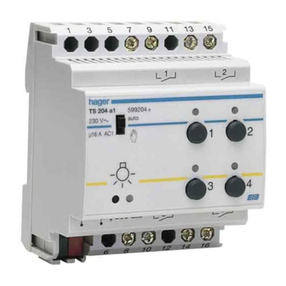
  9. hager TS 204 Installation instructions

hager TS 204 Installation instructions

Nota : Les différentes sorties peuvent être raccordées sur des phases différentes.
Hinweis : Die Schaltausgänge können an unterschiedliche Phasen angeschlossen werden.
Note : The outputs can be connected to different phases.
Nota : De verschillende uitgangen kunnen op verschillende fasen aangesloten worden.
Nota : Le diverse uscite possono essere collegate su fasi differenti.
Nota : As diferentes saídas podem ser ligadas a diferentes fases.
Anmärkning : utgångarna kan anslutas till olika faser.
TS 204 auto
34
12
L
N
13 79 1315
810 14
511
61216
6T 7069.a
TS 204
Raccordement électrique
Anschlußbild
Electrical connection
Elektrische aansluiting
Colegamenti elettrici
Ligação eléctrica
Elektrisk inkoppling
24 mois contre tous vices de matières ou de fabrication, à
partir de leur date de production. En cas de défectuosité, le
produit doit être remis au grossiste habituel.
La garantie ne joue que si la procédure de retour via l’instal-
lateur et le grossiste est respectée et si après expertise notre
service contrôle qualité ne détecte pas un défaut dû à une
mise en œuvre et/ou une utilisation non conforme aux règles
de l’art.
Les remarques éventuelles expliquant la défectuosité devront
accompagner le produit.
Garantie F
Recommandations de mise en œuvre
Es gelten die Allgemeinen Geschäfstbedingungen der Hager Electro
GmbH. bzw. die gesetzliche Regelung.
Garantie D
FDGB
Notice d’instructions
Installationsanleitung
User instruction
Bedieningshandleiding
Istruzioni d’impiego
Instruções de instalação
Bruksanvisning
Module de sortie pour l’éclairage
4 contacts 16A 230V libres de potentiel
Schaltausgang
4 potentialfreie Schließer 16A 230V
Switch output
4 voltage free NO contacts 16A 230V
Uitgangsmodule voor de verlichting
4 kontakten 16A 230V vrij van potentieel
Modulo di uscita per l’illuminazione
4 contatti 16A 230V liberi da potenziale
Módulo de saída para iluminação
4 contactos 16A 230V livres de potencial
Belysningsaktor
med 4 potentialfria kontakter 16A 230V
F
GB
D
NL
P
S
I
A warranty period of 24 months is offered on hager products,
from date of manufacture, relating to any material of manu-
facturing defect. If any product is found to be defective it must
be returned via the installer and supplier (wholesaler).
The warranty is withdrawn if :
- after inspection by hager quality control dept the device is
found to have been installed in a manner which is contrary to
IEE wiring regulations and accepted practice within the industry
at the time of installation.
- the procedure for the return of goods has not been followed.
Explanation of defect must be included when returning
goods.
Warranty GB
Légende :
➀Bus 29 V TBTS
➁Commutateur Auto / Manu
➂Bouton-poussoir Test / adressage
➃Visualisation de l’état de la sortie
➄Bouton-poussoir pour
a) la programmation
b) le forçage des sorties en position
du commutateur Auto/Manu
➅Sorties 1 et 3
➆Sorties 2 et 4.
Legende :
➀Systemspannung 29 V DC (SELV)
➁Wahlschalter Auto / Manu
➂Prüf/adressierungs Taste
➃Schaltzustandsanzeige
➄Bedientasten:
a) Programmierung
b) Handbedienung
➅Ausgang 1 und 3
➆Ausgang 2 und 4
Legend :
➀System voltage 29V DC (SELV)
➁Selection switch Auto / Manu
➂Test / adressing button
➃Indication of switch state
➄Operating push buttons :
a) Programming
b) Manuel operation
➅Output 1 and 3
➆Output 2 and 4
Legende :
➀Bus 29 V ZLVS
➁Keuzeschakelaar Auto / Manu
➂Drukknop Test / adressing
➃Visualisering van de uitgangstoestand
➄Drukknop voor
a) de programmatie
b) forcering van de uitgangen bij stand
van de keuzeschakelaar Auto/Manu
➅Uitgang 1 and 3
➆Uitgang 2 and 4
Legenda :
➀Bus 29 V SELV
➁Commutatore Auto / Manu
➂Pulsante Test / indirizzamento
➃Visualizzazione dello stato dell’uscita
➄Pulsante per :
a) la programmazione
b) la forzatura delle uscite nella posizione
del commutatore Auto/Manu
➅Uscita 1 e 3
➆Uscita 2 e 4
Legenda :
➀Bus 29 V MBTS
➁Comutador Auto / Manu
➂Botão de pressão Teste / endereçamento
➃Visualização do estado da saída
➄Botão de pressão para :
a) programação
b) forçagem das saídas na posição
do comutador Auto / Manu
➅Saídas 1 e 3
➆Saídas 2 e 4
➀
➁
➂
➃
➄
➅
230 V M
16A AC1
auto
34
12
TS 204
Principe de fonctionnement
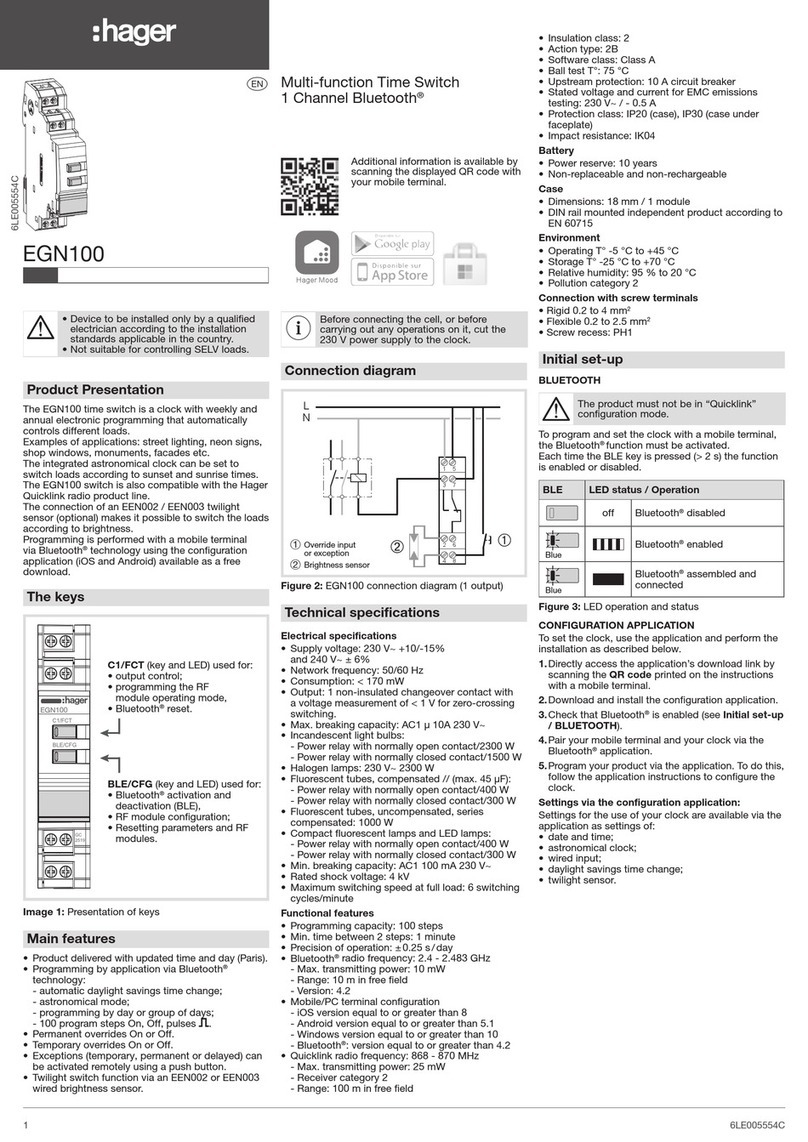
Le module TS 204 assure :
- l’allumage et l’extinction des appareils
d’éclairage
- la mise en service et l’arrêt des prises de
courants commandées
- la mise en service et l’arrêt de la VMC
- la commande d’appareils électriques
nécessitant un contact libre de potentiel.
En mode “Auto”, les ordres d’allumage et
d’extinction proviennent des modules
d’entrées du système Tébis TS.
En mode “Manu” , ces commandes sont
accessibles par les boutons poussoirs en
façade du module (forçage).
Spécifications techniques
Caractéristiques électriques
●tension d’alimentation : bus 29V
●consommation : 5 mA
●dissipation maximum du produit : < 1 W
Caractéristiques fonctionnelles
●pouvoir de coupure :
- AC1 : 16 A 250 V
- incandescent : 2 000 W
- halogène BT et TBT : 1 600 W
●durée de vie des contacts :
- 16 A AC1 : 360 000 manœuvres
- incandescent 2 000 W : 250 000 manœuvres
- halogène BT et TBT 1 600 W :
250 000 manœuvres
Environnement
●T° de fonctionnement : 0 °C à +45 °C
●T° stockage : -20 °C à +70 °C
Raccordement
●capacité : souple: 1 mm2à 6 mm2
rigide : 1,5 mm2à 10 mm2
Encombrement : dimensions : 4 modules
Funktionsbeschreibung
Ausgangsgerät mit 4 Schließerkontakten zum
Schalten von Beleuchtungs- oder
Steckdosenkreisen oder anderer Verbraucher.
Der TS 204 wird über die Systemleitung von
den zugeordneten Bus Eingängen gesteuert.
Das Gerät verfügt zusätzlich über Handbedien-
möglichkeit und Schaltzustandsanzeige für
EIN/AUS.
Inbetriebnahmehinweise:
Technische Daten
Elektrische Daten
●Versorgungsspannung: Systemspannung 29 V
●Leistungsaufnahme: 5 mA
●Verlustleistung: < 1 W
Betriebsdaten
●Kontaktbelastbarkeit
- 16 A AC1 250 V
- 2 000 W Glühlampen
- 1 600 W: 230 V und NV Halogen
●Kontaktlebensdauer:
- 360 000 Schaltspiele bei 16 A AC1
- 250 000 Schaltspiele bei 2 000 W
Glühlampen und Halogen 1 600 W
Umgebung
●Betrieb: 0 °C bis +45 °C
●Lagerung: -20 °C bis +70 °C
Anschluß
●Käfigklemmen: flexibel: 1 mm2bis 6 mm2
massiv: 1,5 mm2bis 10 mm2
Abmessungen: Größe: 4 PLE
Function
Output device with 4 NO contacts to switch
lighting or socket circuits or other consumers.
The TS 204 is controlled over the system line
by allocated bus inputs.
The device also provides a manual override
facility and a visual indicator ON/OFF.
Installation instructions:
Technical Specifications
Electrical data
●Supply voltage: System voltage 29 V
●consumption : 5 mA
●watts loss: < 1 W
Operation data
●contact’s loading capacity Indicator:
- AC1: 16 A 250 V
- 2 000 W incandescent lamps
- 1 600 W halogen
●electrical endurance:
- 360 000 operations at 16 A AC1
- 250 000 operations at
2 000 W incandescent lamps
- 250 000 operations at 1 600 W halogen
Environment
●operation: 0 °C to +45 °C
●storage: -20 °C to +70 °C
Connection
●cage clamps: flexible: 1 mm2to 6 mm2
rigid: 1.5 mm2to 10 mm2
Dimensions : size: 4 modules
➆
➅➆
Funktioner :
➀Systemspänning 29V DC (SELV)
➁Hand / Autoomkopplare
➂Test / adresserings knapp
➃Indikering av kontaktstatus
➄Manöverknappar:
a) Programmering
b) Manuell styrning
➅Utgång 1 och 3
➆Utgång 2 och 4
Attention :
-Appareil à installer uniquement
par un installateur électricien.
-Ce module est un élément du
système TEBIS TS, il est
fonctionnellement indissociable
des autres modules du système.
-Respecter les règles d’installation TBTS.
Sicherheitshinweise:
-Einbau und Montage dürfen nur durch
eine Elektrofachkraft erfolgen.
-Die Funktion des Geräts ist nur
innerhalb des Systems tebis TS gegeben.
-Installationsvorschriften zur
Schutzmaßnahme SELV beachten.
Safety Recommendations:
-Installation should only be carried
out by a suitably qualified electrician
-This device’s function is only
possible within the system tebis TS.
-Observe the installation regulations
of the protection measures SELV.
1. Installer le module dans le bas de l’armoire
pour éviter une température de fonctionne-
ment trop élevée.
2. Raccorder le module au secteur 230 V et
au bus 29 V.
3. Raccorder les équipements électriques aux
différentes sorties du module.
4. Tester le raccordement 230 V :
- positionner le commutateur Auto/Manu
en position
- appuyer sur les différents boutons-poussoirs
- vérifier l’allumage et l’extinction des équi-
pements électriques connectés aux
différentes sorties du module.
5. Tester le raccordement du bus 29 V :
- positionner le commutateur Auto/Manu
en position “auto“
- un défaut de raccordement du bus 29 V
est signalé par un clignotement simultané
des 4 voyants sur le module.
6. Suivre les instructions du Guide de
Configuration Tébis TS pour réaliser les
liaisons avec les modules d’entrées.
1. Betriebstemperatur beachten. Gerät im unteren
Bereich des Verteilers montieren.
2. Hilfsspannung 230 V AC und Systemspannung
anschließen.
3. Ausgänge anschließen.
4. Funktion der Ausgänge überprüfen:
- Wahlschalter in Stellung bringen
- Verbraucher durch Drücken der Bedientasten
schalten.
5. Anschluß der Systemspannung überprüfen
- Wahlschalter in Stellung “auto” bringen
- Bei Fehlen der Systemspannung blinken alle
Schaltzustandsanzeigen.
6. Inbetriebnahmehinweisen der
Bedienungsanleitung tebis TS folgen
1. Observe operation temperature. Mount
device in lower part of the enclosure.
2. Connect auxiliary voltage 230 V AC and
system voltage.
3. Connect outputs.
4. Verify the outputs’ function :
- put selection switch into position
- switch loads by pushing the push buttons.
5. Verify connection of system voltage
- put selection switch into position “auto”.
- in case of absence of system voltage all
state indicators flash.
6. Observe the rules of the tebis TS operating
instruction.

Other hager Switch manuals

hager EE100 User manual

hager

hager EE100 User manual

hager EH712 User manual

hager

hager EH712 User manual

hager EGN100AU User manual

hager

hager EGN100AU User manual

hager SR000AO User manual

hager

hager SR000AO User manual

hager EGN200AU User manual

hager

hager EGN200AU User manual

hager WBMSLL User manual

hager

hager WBMSLL User manual

hager SP 802 User manual

hager

hager SP 802 User manual

hager kallysta WKT30 R Series User manual

hager

hager kallysta WKT30 R Series User manual

hager EE200 User manual

hager

hager EE200 User manual

hager EGN100 User manual

hager

hager EGN100 User manual

hager EE110 User manual

hager

hager EE110 User manual

hager HIC4 A Series User manual

hager

hager HIC4 A Series User manual

hager TX 206A User manual

hager

hager TX 206A User manual

hager WHT390 User manual

hager

hager WHT390 User manual

hager TS 244 Operator's manual

hager

hager TS 244 Operator's manual

hager EMN005 User manual

hager

hager EMN005 User manual

hager HIC4 G Series User manual

hager

hager HIC4 G Series User manual

hager WXT30 Series User manual

hager

hager WXT30 Series User manual

hager EG071 User manual

hager

hager EG071 User manual

hager EMN005 User manual

hager

hager EMN005 User manual

hager HIC4 T Series User manual

hager

hager HIC4 T Series User manual

hager EE701 User manual

hager

hager EE701 User manual

hager HI460 User manual

hager

hager HI460 User manual

hager EG 470 Installation instructions

hager

hager EG 470 Installation instructions

Popular Switch manuals by other brands

dji AIR 3 user guide

dji

dji AIR 3 user guide

TRENDnet TI-PG80 Quick installation guide

TRENDnet

TRENDnet TI-PG80 Quick installation guide

Juniper QFX5110 Hardware documentation

Juniper

Juniper QFX5110 Hardware documentation

Potter VSR-AT Series manual

Potter

Potter VSR-AT Series manual

DigitaLinx DL-S41 installation guide

DigitaLinx

DigitaLinx DL-S41 installation guide

Cisco Nexus 7710 Site Preparation and Hardware Installation Guide

Cisco

Cisco Nexus 7710 Site Preparation and Hardware Installation Guide

FS S5500-48T8SP Configuration Preparation Guide

FS

FS S5500-48T8SP Configuration Preparation Guide

Atlas ASL-6A installation instructions

Atlas

Atlas ASL-6A installation instructions

Allied Telesis AT-8624T/2M, AT-8624PoE datasheet

Allied Telesis

Allied Telesis AT-8624T/2M, AT-8624PoE datasheet

Delta Electronics Agema Series installation guide

Delta Electronics

Delta Electronics Agema Series installation guide

ORiNG IGS-1050A Quick installation guide

ORiNG

ORiNG IGS-1050A Quick installation guide

CYP EL-C41C Operation manual

CYP

CYP EL-C41C Operation manual

Castelle Office Connect user guide

Castelle

Castelle Office Connect user guide

Juniper EX Series quick start guide

Juniper

Juniper EX Series quick start guide

CYP EL-31SY Operation manual

CYP

CYP EL-31SY Operation manual

Airlinkplus AKVM-4 Quick installation guide

Airlinkplus

Airlinkplus AKVM-4 Quick installation guide

Algo 1203 Getting Started Sheet

Algo

Algo 1203 Getting Started Sheet

Gefen HDSDI-441N user manual

Gefen

Gefen HDSDI-441N user manual

manuals.online logo
manuals.online logoBrands
  • About & Mission
  • Contact us
  • Privacy Policy
  • Terms and Conditions

Copyright 2025 Manuals.Online. All Rights Reserved.