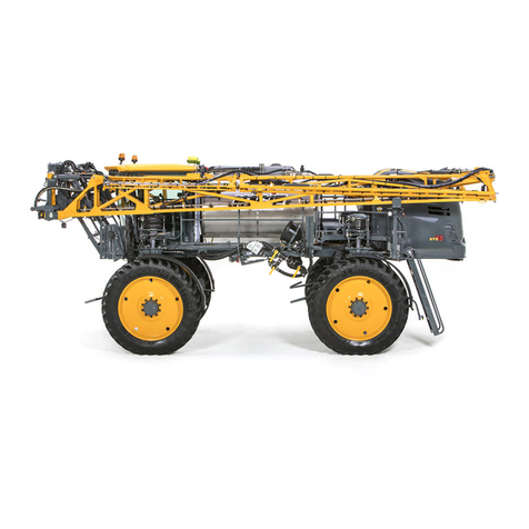
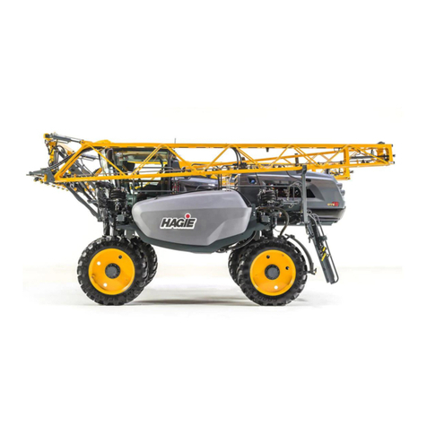
Hagie DTS 10 User manual

5 - DASH / AUTO
2019 DTS10
OPERATOR’S MANUAL
493799
CALIFORNIA
Proposition 65 Warning
Diesel engine exhaust and some of its
constituents are known to the State of
California to cause cancer, birth defects,
and other reproductive harm.

5 - DASH / AUTO

CONTENTS
5 - DASH / AUTO
Covers Machine Serial Numbers: DTS10 19001-19500 Part No. 493799
© 2018-19 Hagie Manufacturing Company. Clarion, Iowa USA Rev. 19D190412
Some of the material used in this manual may be the reproduced works of Deere & Co.
1 – INTRODUCTION
A Word From Hagie Manufacturing Company ...................................................................1-1
About This Manual .............................................................................................................1-1
Safety Messages Used In This Manual .............................................................................1-2
Service and Assistance ......................................................................................................1-2
Product Warranty ...............................................................................................................1-2
Identification .......................................................................................................................1-2
Specifications .....................................................................................................................1-5
Torque Values ..................................................................................................................1-16
2 – SAFETY AND PRECAUTIONS
Intended Use ......................................................................................................................2-1
Safety Precautions .............................................................................................................2-1
Seat Belt ............................................................................................................................2-7
Rotating Beacon ................................................................................................................2-7
Emergency Stop ................................................................................................................2-7
Emergency Exit ..................................................................................................................2-8
Fire Extinguisher ................................................................................................................2-9
Safety Decals .....................................................................................................................2-9
3 – CAB
Seat - Operator (Standard) ................................................................................................3-1
Seat - Operator (Premium) ................................................................................................3-4
Seat - Instructor .................................................................................................................3-7
Operator’s Station ..............................................................................................................3-7
Machine Display ...............................................................................................................3-33
4 – ENGINE AND DRIVE SYSTEMS
Engine - Starting ................................................................................................................4-1
Engine Aftertreatment - Final Tier 4 ...................................................................................4-3
Hydrostatic Drive ..............................................................................................................4-10
All-Wheel Steer (AWS) ....................................................................................................4-15
5 – HYDRAULIC SYSTEMS
Hydraulic System Components ..........................................................................................5-1
Reversible Fan - Variable Pitch .........................................................................................5-4
Tread Adjustment - Hydraulic ............................................................................................5-6
Ladder ................................................................................................................................5-9
Pressure Washer .............................................................................................................5-10
6 – ELECTRICAL SYSTEMS
Batteries .............................................................................................................................6-1
Battery Disconnect Switch .................................................................................................6-2

Fuses and Relays ..............................................................................................................6-4
Fuse and Relay Ratings .....................................................................................................6-8
7 – SPRAY SYSTEMS
Spray Booms .....................................................................................................................7-1
Spray Boom - Rear ..........................................................................................................7-14
Solution System Components ..........................................................................................7-16
Solution System - Operation ............................................................................................7-25
Fence Row Applicator ......................................................................................................7-29
Filling Your Solution Tanks ..............................................................................................7-30
Draining Your Solution Tanks ..........................................................................................7-33
Rinse System ...................................................................................................................7-34
Solution Pump Re-Priming ...............................................................................................7-38
Foam Marker System .......................................................................................................7-42
Eductor System ................................................................................................................7-45
Modular Injection System .................................................................................................7-49
Application .......................................................................................................................7-59
8 – MAINTENANCE AND STORAGE
Service - Fluids ..................................................................................................................8-1
Service - Filters ................................................................................................................8-11
Service - Lubrication ........................................................................................................8-22
Service - Engine Drive Belt ..............................................................................................8-24
Service - Bolt Torque .......................................................................................................8-24
Service - Toe-In ...............................................................................................................8-27
Service - Miscellaneous ...................................................................................................8-29
Service Intervals ..............................................................................................................8-34
Storage ............................................................................................................................8-36
9 – MISCELLANEOUS
Transporting .......................................................................................................................9-1
Lifting Your Machine ..........................................................................................................9-4
Air Suspension Exhaust .....................................................................................................9-6
Viscous Clutch Fan ............................................................................................................9-6
Hand Wash System ...........................................................................................................9-8
Electric Hood ....................................................................................................................9-10
Front End Access .............................................................................................................9-11
Tread Adjustment - Manual ..............................................................................................9-12
Tall Crop Package - Installation .......................................................................................9-15
Troubleshooting ...............................................................................................................9-22

1-1
5 - DASH / AUTO
SECTION 1 – INTRODUCTION
A WORD FROM HAGIE
MANUFACTURING
COMPANY
Congratulations on the purchase of your
DTS10 Sprayer! Read this operator’s manual
and become familiar with operating
procedures and safety precautions before
attempting to operate your sprayer.
As with any piece of equipment, certain
operating procedures, service, and
maintenance are required to keep your
machine in top running condition. We have
attempted herein to cover all of the
adjustments required to fit varying
conditions. However, there may be times
when special care must be considered.
NOTE: The operator is responsible for
inspecting the machine and having
parts repaired or replaced when
continued use of the product causes
damage or excessive wear to other
parts.
Hagie Manufacturing Company reserves
the right to make changes in the design and
material of any subsequent sprayer without
obligation to existing units.
Thank you for choosing a Hagie sprayer
and we ensure you of our continued interest
and support in its optimal performance for
you. We are proud to have you as a
customer!
ABOUT THIS MANUAL
This manual will aid you in the proper
operation and service of your machine. It is
the responsibility of the user to read the
operator’s manual and comply with the
correct and safe operating procedures, as
well as maintain the product according to the
service information provided in the
MaintenanceandStorage Section elsewhere
in this manual.
Photographs and illustrations used in this
manual are of general nature only. Some of
the equipment and features shown may not
be available on your machine.
Information described in this manual was
correct at the time of printing. Because of
Hagie Manufacturing Company’s continuous
product improvement, certain information
may not be included in this manual. To obtain
the most current operator’s manual for your
machine, please visit www.hagie.com.
Keep this manual in a convenient place for
easy reference. This manual is considered a
permanent fixture of the product. In the event
of resale, this manual must accompany the
machine.
If you do not understand any part of this
manual or require additional information or
service, contact your local John Deere dealer
for assistance.
NOTICE
Any pictures or illustrations contained
within this manual that depict situations
with shields, guards, rails, or lids
removed are for demonstration only.
Keep all shields and safety devices in
place at all times.
SECTION 1 –
INTRODUCTION
1-2
SAFETY MESSAGES USED
IN THIS MANUAL
The following safety messages found
throughout this manual alert you of situations
that could become potentially dangerous to
the operator, service personnel, or
equipment.
NOTE: A “Note” is intended to make special
mention of, or remark on.
SERVICE AND ASSISTANCE
Please contact your local John Deere
dealer for service and assistance.
PRODUCT WARRANTY
Please contact your local John Deere
dealer for further information.
IDENTIFICATION
Each machine is identified by means of a
frame serial number. This serial number
denotes the model, year in which it was built,
and the number of the sprayer.
For further identification, the engine,
solution pump, and hydraulic pumps each
have serial numbers, and the planetary
wheel motor/hubs have identification plates
that describe the type of mount and gear
ratio.
To ensure prompt, efficient service when
ordering parts or requesting service repairs,
record the serial numbers and identification
numbers in the following spaces provided.
Machine
The machine serial number is stamped on
the front right-hand side of frame (behind the
front leg).
DANGER
The signal word DANGER indicates a
hazardous situation which, if not
avoided, will result in death or serious
injury.
WARNING
The signal word WARNING indicates a
hazardous situation which, if not
avoided, could result in death or serious
injury.
CAUTION
The signal word CAUTION indicates a
hazardous situation which, if not
avoided, could result in minor or
moderate injury. CAUTION may also be
used to alert against unsafe practices
associated with events which could lead
to personal injury.
NOTICE
The signal word NOTICE indicates
operator awareness which, if not
avoided, may result in personal or
property damage.
NOTICE
Reference to right and left-hand used
throughout this manual refers to the
position when seated in the operator’s
seat facing forward.

1-3
SECTION 1 –
INTRODUCTION
Engine
The engine has an identification plate
mounted on top of the engine that provides
engine serial number, as well as other
manufacturer information. Refer to your
Parts Manual for specific part number.
Solution Pump
The solution pump has an identification
plate mounted on the side of pump that
provides pump serial number, as well as
other manufacturer information. Refer to your
Parts Manual for specific part number.
Hydraulic Pumps
The PC and Drive Pumps each have an
identification plate mounted on the side of
pump that provides pump serial number, as
well as other manufacturer information. Refer
to your Parts Manual for specific part
number.
Machine Serial Number
-Typical View
Serial No. _______________________
Engine Identification Plate
-Typical View
Serial No. _______________________
Solution Pump Identification Plate
* View shown from beneath machine
-Typical View
Serial No. _______________________
Hydraulic Pumps
-Typical View
________________________ PC Pump
________________________ Drive Pump
•PC
Pump
•Drive
Pump

SECTION 1 –
INTRODUCTION
1-4
Wheel Motor/Hubs
Each wheel motor/hub assembly has an
identification plate mounted on the rear side
of the hub that provides serial number, as
well as other manufacturer information,
including gear ratio. Refer to your Parts
Manual for specific part number.
Wheel Motor/Hub Assembly
-Typical View
_________________________ Right Front
_________________________ Right Rear
_________________________ Left Front
_________________________ Left Rear

1-5
SECTION 1 –
INTRODUCTION
SPECIFICATIONS
Machine Dimensions
NOTE: Dimensions on your machine may vary, depending on tire size.
Detail Description Specification
AOverall Sprayer Height (from top of cab)
NOTE: Overall machine height dimension does not include the cab-
mounted rotating beacons or the optional GPS unit.
• 149.5”/379.3 cm (air
bags inflated) **
• 144”/365.8 cm (air bags
deflated) **
B Raised Transom Height 150.8”/383 cm **
C1 Transom Height - Fully Raised 106”/269.2 cm
C2 Transom Height - Fully Lowered 24”/61 cm
C3 Transom Lift Range (C1 minus C2) 82”/208.3 cm
D Static Loaded Hub Height 28.6”/72.6 cm **
EWheel Base 139.4”/354.1 cm
F Sprayer Length
NOTE: Overall machine length does not include the optional rear boom. 326”/828 cm
GWidth (booms folded) 156”/396.2 cm
H Frame Clearance (to mainframe) 72”/182.9 cm **
ILower Leg Clearance 23”/58.4 cm **
J Tread Width* • In = 120”/304.8 cm **
• Out = 160”/406.4 cm **

SECTION 1 –
INTRODUCTION
1-6
* Tread width is measured from center of tire at
ground.
** Refer to “Tire Specifications” provided else-
where in this section for a complete listing of tire
options when configuring machine specifications
on your model.
General Information
•Frame Type: 3 x 8” (7.6 x 20.3 cm)
modular platform frame
•Suspension: 4-wheel, individual, auto
air-ride
•Shipping Width: 156”/396.2 cm
(from outside of each solution tank)
•Approximate Dry Weight:
19,654 lbs./8,914 kg
NOTICE
Because Hagie Manufacturing
Company offers a variety of options, the
illustrations in this manual may show a
machine equipped other than standard.
Machine dimension and weight values
may vary, depending on available
equipment.

1-7
SECTION 1 –
INTRODUCTION
Spray System GPS Specifications
-If Equipped
NOTE: Dimensions on your machine may vary, depending on tire size.
Detail Description Specification
AWheel Base 139.4” (354.1 cm)
B Static Loaded Hub Height 28.6” (72.6 cm)
COverall Sprayer Height (from middle of GPS unit) 152.1” (386.3 cm)
D Length
(from front of boom spray tips to center of GPS unit)
114” (289.6 cm)
ELength (from center of GPS unit to center of rear hub) 97” (246.4 cm)

SECTION 1 –
INTRODUCTION
1-8
Settings and Calibration
Record settings and calibration values
used in the following spaces provided when
programming your spray system console.
Refer to this information for future reference.
Record calculated calibration values in the spaces provided below.
Speed Cal Section
Widths
Meter Cal Rate Cal Valve Cal Tank Volume
1. 1. 1. 1. 1. 1.
2. 2. 2. 2. 2.
3. 3. 3. 3. 3.
4. 4. 4. 4. 4.
5. 5. 5. 5. 5.
6.
7.
8.
9.
10.

1-9
SECTION 1 –
INTRODUCTION
Machine Specifications
Description Specification
Engine
Manufacturer Cummins®
Model QSB 6.7
Type Electronic with air-to-air cooler and turbo
charger
Number of Cylinders 6
Displacement 6.7 liters (408.9 c.i.)
Horse Power •Final Tier 4 - 225 hp/165 KW
•Tier 3 - 215 hp/158 KW (Export only)
Fuel Type •Final Tier 4 - Ultra-low sulfur diesel (ULSD)
•Tier 3 - No. 2 diesel (Export only)
Fuel System Filtered, direct-injected
Air Cleaner Dry-type, dual element
Engine Air Filter Restriction Monitors Filter Minder®
Slow Idle 850 RPM
Fast Idle (no load) 2500 RPM
Hydrostatic Drive
Hydrostatic Pump Danfoss H1-Series
Drive Train All-Wheel 4-Wheel Drive
Speed Ranges • Speed Range 1 (0-14 mph, 0-22.5 km/h)*
• Speed Range 2 (0-20 mph, 0-32 km/h)*
• Speed Range 3 (0-30 mph, 0-48 km/h)* - Road
Mode only
* Speed ranges may vary, depending on tire size.
Wheel Motors/Final Drive Fairfield Torque-Hub® (CT07)
• Lubrication Oil bath
Brakes (Parking) Multiple disk, spring applied, hydraulically
released
Auxiliary Hydraulic System
Steering System Hydraulic, priority circuit
• Control Full-time power
• Steering Cylinders Double acting

SECTION 1 –
INTRODUCTION
1-10
• Turning Radius^
(Measured from center point to center of tracks)
NOTE: May vary, depending on tire size.
• 12.04 ft./3.5 m (AWS “On”, if equipped)
• 19.29 ft./5.5 m (No AWS/AWS “Off”)
All Wheel Steer (AWS) - if equipped^ Coordinated steering
Solution System Hydraulic Pump Gear pump
Spray System
Booms • 60/80-ft. (7 sections)
• 60/90-ft. (7 sections)
• Type 0.5” (1.3 cm) schedule 5 stainless wet boom
plumbing
• Controls Electro-hydraulic (fold/lift/level)
• Outer Boom Hydraulic Breakaway Self-actuated, reset electrically
Solution Fill Connection
• Quick-fill Connection 2” (5 cm) inner diameter
Solution Tanks (2) 500 gallons (1892 L)/each
Agitation Jet-type with electric valve variable control
General Spray System
• Pump • Centrifugal-hydraulically driven w/proportional
control valve
• Hypro® 9303C-HM1C w/silicon carbide seals
• Flow Meter • TeeJet® 802
• Turbine type with sapphire bearing
• Usable range = 3-130 GPM (11.4-492.7 l/min)
• Diagnostic LEDs for easy troubleshooting
• Solution Valves Ball valves (electric)
• Pressure Gauge 160 PSI (11 bar), glycerin filled
• Console • Raven (optional)
• Ag Leader® (optional)
• John Deere (optional)
• Fence Row Nozzle Remote activated (left and right)
• Rear Wheel Nozzle Remote activated
Solution Circuit Pressure 100 PSI (6.9 bar) - maximum
Modular Injection System (if equipped)
Chemical Tank(s) 45-gallons (170 L)/each
Injection Pump(s) Raven Sidekick Pro™ (5-200 oz./min.)
Mixer 3” (7.6 cm) poly

1-11
SECTION 1 –
INTRODUCTION
Foam Marker System
Make Hagie Concentrate Foamer
Type Boom Mix
Rinse System
Spray System Rinse
(solution tanks, pump, and booms)
2 rotating rinse balls (inside each tank)
Air Purge - if equipped Remote activated (purges downstream from flow
meter through boom plumbing)
Electrical System
General Electrical System
• Battery Dual 12V, negative ground (CCA)
• Alternator 200 AMP, voltage regulated
• Starter 12V with solenoid
Lights (Exterior)
• Front of Cab 2 trapezoidal headlights, 2 floodlights, 2 rotating
amber beacon lights
• Transom 2 trapezoidal headlights
• Transom Mount 2 trapezoidal headlights (high/low beam), 2 oval
amber lights (combined)
• Tank Cradle 2 oval amber lights (1 on each cradle)
• Rear Engine Hood 2 round red lights, 2 round amber lights
• Spray Boom Indicators
(located on boom, if equipped)
7 oval green lights
• Night Spray - if equipped 2 flood lights (rear of cab), 2 spot beam lights
(facing boom tip)
Cab and Instruments
Sound Level (cab interior) 77.8 dBa (maximum)
Cab (General) Tilt steering, wipers/washers, dual side mirrors,
dome light, tinted glass, instructor seat
Cab Door Width (opening width) 22” (55.9 cm)
Temperature Control Full range
A/C Charge Type R-134A
Fresh Air Filtration • RESPA® cab filter
• Charcoal filter
Seat • Mechanical (standard)
• Air-ride (optional)

SECTION 1 –
INTRODUCTION
1-12
^ Operators with machines equipped with All-Wheel Steer (AWS) pay special attention.
Instruments Tachometer (RPM), fuel level, engine coolant
temperature, after-treatment level
Machine Display Hour meter, battery voltage, engine oil pressure,
ground speed, engine diagnostics, tread
adjustment, parking brake, machine/engine
malfunction warnings, engine exhaust filtration
warning, high exhaust temperature warning, low
hydraulic oil level, low coolant level, low fuel
level, grid heater, cab air pressure
Stereo AM/FM radio, MP3, Bluetooth
Fluid Capacities
Solution Tanks (2) 500 gallons (1892L)/each
Fuel Tank 100 gallons (378.5L)
Engine Oil Pan (including filter and cooler) 17.6 quarts (16.7L), John Deere Plus-50™ II
Engine Oil Dipstick (L-H mark) 2 quarts (1.9L)
Engine Cooling System
(including block, lines, and radiator)
• Final Tier 4 - 10 gallons (37.9L), John Deere
Cool -Gard™ II
•Tier 3 - 9.55 gallons (36.2L), John Deere Cool
-Gard™ II (Export only)
Diesel Exhaust Fluid (DEF) Tank
(Tier 4 Final Engines)
5 gallons (18.9L), John Deere Diesel Exhaust
Fluid (DEF)
Hydraulic Oil (including lines, filter, cooler, etc.) 39 gallons (147.5L), John Deere Hy-Gard™
Hydraulic Oil Reservoir 25 gallons (94.5L)
Wheel Hubs (4) 27 oz. (.8 L)/each, 75W-90 gear oil
Rinse Tank 100 gallons (378.5L)
Hand Wash Tank 4 gallons (15L)
Foam Marker Tank 1 gallon (3.8L), foam concentrate
Air Conditioning System (Charge) 3.50 lbs. (1.59 kg), R-134A

1-13
SECTION 1 –
INTRODUCTION
Tire Specifications
* Static load radius is suggested and will vary with load.
NOTICE
Do not exceed tire load limit. Failure to
comply will result in weight overload and
will void the warranty.
TIRE SPECIFICATIONS (STANDARD)
Size Make Model Load
Rating
(Weight/
Speed)
Air
Pressure
(Max PSI)
Tread
Width
(inches)
Load
Capacity
(lbs.)
Overall
Diameter
(inches)
Static
Load
Radius*
(inches)
Rolling
Circum.
(inches)
Gross
Flat
Plate
(in2)
380/80R38 Goodyear® Ultra
Sprayer
155A8/B 64 14.6 8,550 62.4 28.2 188 234
IF320/80R42 Goodyear Super
Traction
149D 49 11.7 7,150 62.4 28.2 188 205
380/80R38 Alliance Farm Pro 152A8/B 58 14.8 7,850 62.1 28.7 185.9 231
540/65R30 Alliance 550 161A8/
156D
46 21.5 10,190 57.5 26.2 173.3 288
VF420/85R42 Michelin Yieldbib 154A8/
154B
23 17 8,270 62.3 27.5 184.3 312
TIRE SPECIFICATIONS (METRIC)
Size Make Model Load
Rating
(Weight/
Speed)
Air
Pressure
(Max
Bar)
Tread
Width
(cm)
Load
Capacity
(kg)
Overall
Diameter
(cm)
Static
Load
Radius*
(cm)
Rolling
Circum.
(cm)
Gross
Flat
Plate
(cm2)
380/80R38 Goodyear Ultra
Sprayer
155A8/B 4.4 37.1 3,878 158.5 71.6 477.5 1,510
IF320/80R42 Goodyear Super
Traction
149D 3.4 29.7 3,243 158.4 71.6 477.5 1,322
380/80R38 Alliance Farm Pro 142A8/B 4.0 37.6 3,560 157.7 72.9 472.2 1,490
540/65R30 Alliance 550 161A8/
156D
3.2 54.6 4,622 146.1 66.5 440.2 1,858
VF420/85R42 Michelin Yieldbib 154A8/
154B
1.6 43.2 3,751 158.2 69.9 468.1 2,012

SECTION 1 –
INTRODUCTION
1-14
NOTE: There are no adjustments to the loads and pressures in the above table for lower speeds
or stationary service.
NOTE: Minimum inflation pressures for IF agricultural tires used as singles = 12 psi.
TIRE LOAD LIMITS (LBS) AT VARIOUS COLD INFLATION PRESSURES (PSI)
Inflation
(psi)
6 9 12 15 17 20 23 26 29
380/80R38 Goodyear 2,270 2,760 3,200 3,640 4,180 5,440 5,080 5,360 5,520
IF320/80R42 Goodyear N/A N/A 3,200 3,640 4,080 4,540 4,940 5,200 5,520
380/80R38 Alliance N/A N/A N/A N/A N/A N/A 4,640 4,900 5,040
540/65R30 Alliance 3,350 4,050 4,660 5,410 6,070 6,770 7,460 7,665 8,120
VF420/85R42 Michelin 3,750 4,510 5,270 6,020 6,780 7,520 8,270 N/A N/A
TIRE LOAD LIMITS (LBS) AT VARIOUS COLD INFLATION PRESSURES (PSI)
(CONTINUED)
Inflation
(psi)
35 41 46 52 58 64
380/80R38 Goodyear 5,840 6,400 6,950 7,400 7,850 8,550
IF320/80R42 Goodyear 5,840 6400 6950 N/A N/A N/A
380/80R38 Alliance 5,340 N/A 6,350 6,750 7,150 N/A
540/65R30 Alliance 8,610 9,350 10,190 N/A N/A N/A
VF420/85R42 Michelin N/A N/A N/A N/A N/A N/A

1-15
SECTION 1 –
INTRODUCTION
NOTE: There are no adjustments to the loads and pressures in the above table for lower speeds
or stationary service.
NOTE: Minimum inflation pressures for IF agricultural tires used as singles = .8 bar.
TIRE LOAD LIMITS (KG) AT VARIOUS COLD INFLATION PRESSURES (BAR)
Inflation
(bar)
.4 .6 .8 1.0 1.2 1.4 1.6 1.8 2.0
380/80R38 Goodyear 1,030 1,252 1,451 1,651 1,896 2,468 2,304 2,431 2,504
IF320/80R42 Goodyear N/A N/A 1,451 1,651 1,850 2,059 2,240 2,358 2,503
380/80R38 Alliance N/A N/A N/A N/A N/A N/A 2,104 2,222 2,286
540/65R30 Alliance 1,520 1,837 2,114 2,454 2,753 3,071 3,384 3,477 3,683
VF420/85R42 Michelin 1,700 2,045 2,390 2,730 3,075 3,411 3,751 N/A N/A
TIRE LOAD LIMITS (KG) AT VARIOUS COLD INFLATION PRESSURES (BAR)
(CONTINUED)
Inflation
(bar)
2.4 2.8 3.2 3.6 4.0 4.4
380/80R38 Goodyear 2,649 2,903 3,152 3,357 3,561 3,878
IF320/80R42 Goodyear 2,649 2,903 3,152 N/A N/A N/A
380/80R38 Alliance 2,422 N/A 2,880 3,061 3,243 N/A
540/65R30 Alliance 3,905 4,241 4,622 N/A N/A N/A
VF420/85R42 Michelin N/A N/A N/A N/A N/A N/A

SECTION 1 –
INTRODUCTION
1-16
TORQUE VALUES
Unified Inch Bolt and Screw Torque Values
Torque values listed are for general use only, based on the strength of the bolt or screw. DO
NOT use these values if a different torque value or tightening procedure is given for a specific
application. For plastic insert of crimped steel-type lock nuts, for stainless steel fasteners, or for
nuts on U-bolts, see the tightening instructions for the specific application. Shear bolts are
designed to fail under predetermined loads. Always replace shear bolts with identical grade.
Replace fasteners with the same or higher grade. If higher grade fasteners are used, tighten
these to the strength of the original. Make sure fastener threads are clean and that you properly
start thread engagement. When possible, lubricate plain or zinc plated fasteners other than lock
nuts, wheel bolts or wheel nuts, unless different instructions are given for the specific application.
Bolt or
Screw
Size
SAE Grade 1 SAE Grade 2aSAE Grade 5, 5.1, or 5.2 SAE Grade 8 or 8.2
LubricatedbDrycLubricatedbDrycLubricatedbDrycLubricatedbDryc
N∙m lb.-in. N∙m lb.-in. N∙m lb.-in. N∙m lb.-in. N∙m lb.-in. N∙m lb.-in. N∙m lb.-in. N∙m lb.-in.
1/4 3.7 33 4.7 42 653 7.5 66 9.5 84 12 106 13.5 120 17 150
N∙m lb.-ft. N∙m lb.-ft.
5/16 7.7 68 9.8 86 12 106 15.5 137 19.5 172 25 221 28 20.5 35 26
N∙m lb.-ft. N∙m lb.-ft.
3/8 13.5 120 17.5 155 22 194 27 240 35 26 44 32.5 49 36 63 46
N∙m lb.-ft. N∙m lb.-ft. N∙m lb.-ft.
7/16 22 194 28 20.5 35 26 44 32.5 56 41 70 52 80 59 100 74
N∙m lb.-ft.
1/2 34 25 42 31 53 39 67 49 85 63 110 80 120 88 155 115
9/16 48 35.5 60 45 76 56 95 70 125 92 155 115 175 130 220 165
5/8 67 49 85 63 105 77 135 100 170 125 215 160 240 175 305 225
3/4 120 88 150 110 190 140 240 175 300 220 380 280 425 315 540 400
7/8 190 140 240 175 190 140 240 175 490 360 615 455 690 510 870 640
1285 210 360 265 285 210 360 265 730 540 920 680 1030 760 1300 960
1-1/8 400 300 510 375 400 300 510 375 910 670 1150 850 1450 1075 1850 1350
1-1/4 570 420 725 535 570 420 725 535 1280 945 1630 1200 2050 1500 2600 1920
1-3/8 750 550 950 700 750 550 950 700 1700 1250 2140 1580 2700 2000 3400 2500
1-1/2 990 730 1250 930 990 730 1250 930 2250 1650 2850 2100 3600 2650 4550 3350
Other manuals for DTS 10
3
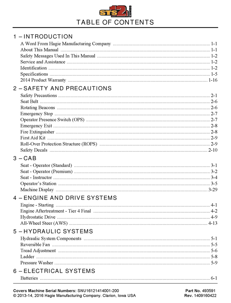
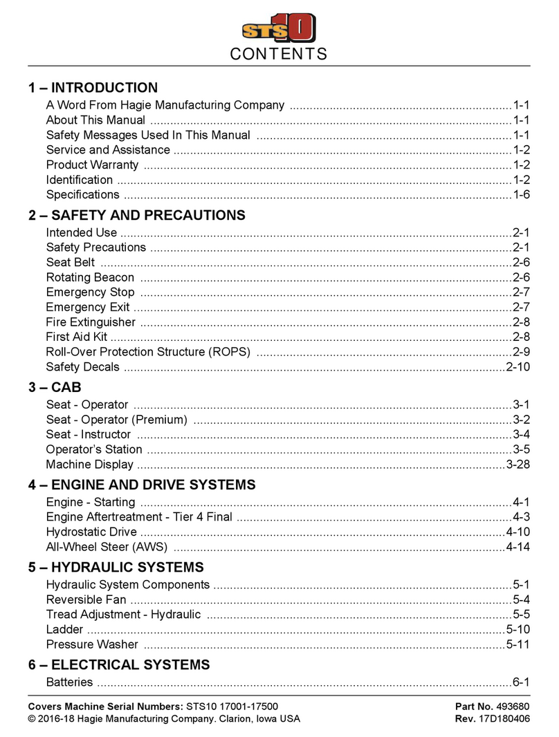
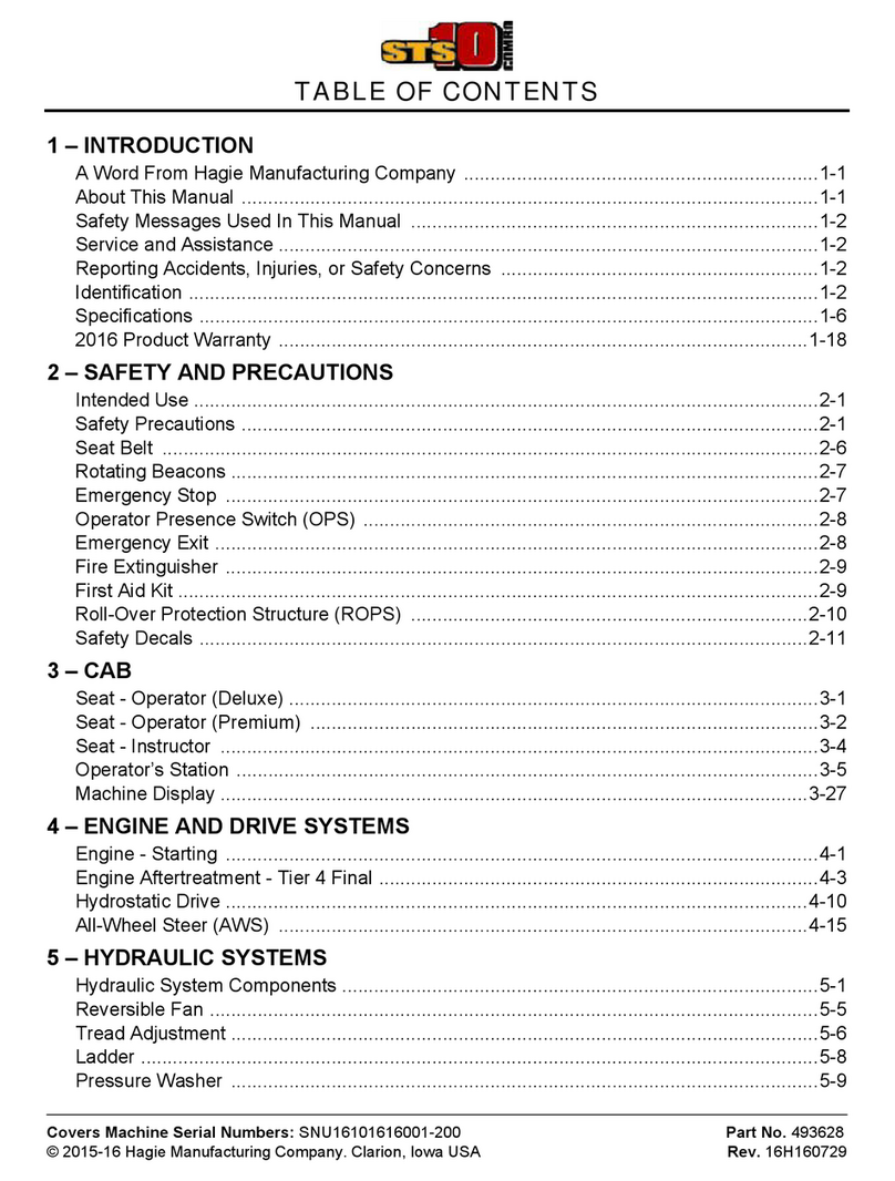
Table of contents
Other Hagie Paint Sprayer manuals

Hagie
Hagie STS 10 Combo User manual

Hagie
Hagie DTS 10 User manual

Hagie
Hagie UpFront STS 14 Combo User manual

Hagie
Hagie STS 10 User manual

Hagie
Hagie STS12i Combo User manual

Hagie
Hagie STS 10 Combo User manual

Hagie
Hagie STS/DPS Series User manual

Hagie
Hagie SmarTrax 2100 Series User manual

Hagie
Hagie STS12i Combo User manual

Hagie
Hagie UpFront STS 16 User manual
Popular Paint Sprayer manuals by other brands

Avanti
Avanti 58056 Owner's manual & safety instructions

C.A. Technologies
C.A. Technologies Jaguar SLP Product information

Graco
Graco 238256 Instructions-parts list

Mesto
Mesto PERLA PLUS 3265P Instructions for use

DeVilbiss
DeVilbiss E P2 – 8 Operation manual

SprayTECH
SprayTECH CAPspray AirCoat 0508074 owner's manual