HAMPTON BAY SRPH78 User manual

THANK YOU
We strive to continually create quality products designed to enhance your home. Visit us online to see our full line of products available
for your home improvement needs. Thank you for choosing Hampton Bay !
Item #
Model # SRPH78
USE AND CARE GUIDE
Devonport tile top Patio Heater
Questions, problems, missing parts? Before returning to the store, call Hampton Bay Customer
Service8 a.m. – 7 p.m., EST, Monday – Friday, 9 a.m. – 6 p.m., EST, Saturday
1-855-HD-HAMPTON
HAMPTONBAY.COM

2
Table of Contents
Table of Contents..........................................................2
Safety Information.........................................................2
Warranty.........................................................................4
What is Covered .......................................................................4
What is Not Covered ................................................................4
Pre-Assembly
................................
..............................4
Planning Assembly...................................................................4
Tools Required
................................
..........................................4
Hardware Included...................................................................4
Package Contents ....................................................................5
Assembly
....................................................
................ 6
Cylinder Installation
...................................................
9
Maintenance.................................................................. 11
Operation....................................................................... 10
Care and Cleaning ........................................................ 11
Trouble Shooting .......................................................... 11
Service Parts ................................................................. 12
Safety Information
DANGER: If you smell gas:
1. Shut off gas to the appliance.
3. If odor continues, keep away from the appliance and
WARNING: For Outdoor Use Only.
WARNING: Do not store or use gasoline or other
any other appliance.
An LP-cylinder not connected for use shall not be
stored in the vicinity of this or any other appliance.
CAUTION: CAUTION: Installer: Leave the instruction
manual to the user for future use.Consumer: Please
keep this manual for future reference.
NOTE: PLEASE READ THE FOLLOWING SAFETY RULES:
Perform a leak test with a soapy solution:
1. To check gas connections.
2. After connecting a new cylinder.
3. Upon re-assembly after disassembly.
CARBON MONOXIDE HAZARD
This appliance can produce carbon monoxide which has
no odor.
Using it in an enclosed space can kill you.
Never use this appliance in an enclosed space such
as a camper, tent, car or home.
: Improper installation, adjustment, alteration, service or maintenance
can cause injury or property damage. Read the installation, operation
and maintenance instructions thoroughly before installing or servicing
this equipment.
WARNING
NOTE: This appliance requires 20 lb (9 kg) LP gas supply
cylinder.
CA65 Propane Warning ..............................................4
....
NOTE: The maximum inlet gas supply pressure: 250 PSI

3
9. Any guard or other protective device removed for servicing the heater must be replaced prior to operating the heater.
annually by a
11. More frequent cleaning may be required as necessary. It is imperative that control compartment, burners and circulating air passageways
of the heater be kept clean.
14. Keeping the ventilation opening(s) of the cylinder enclosure free and clear from debris.
15. This appliance shall be used only in a well-ventilated space and shall not be used in a building, garage or any other enclosed area.
16. An appliance may be installed with shelter no more inclusive than:
17. With walls on all sides, but with no overhead cover.
18. Within a partial enclosure which includes an overhead cover and no more than two side walls. These side walls may be parallel, as in a
breezeway, or at right angles to each other
19. Within a partial enclosure which includes an overhead cover and three side walls, as long as 30 percent or more of the horizontal periphery
of the enclosure is permanently open.
ders of the
U.S.
21. Department of Transportation (DOT); or the Standard for Cylinders, Spheres and Tubes for Transportation of Dangerous Goods and
Commission, CAN/CSA-B339, as applicable;
nection for the
appliance.
23. The cylinder be disconnected when the appliance is not in use.
24. Storage of an appliance indoors is permissible only if the cylinder is disconnected and removed from the appliance.
25. A cylinder must be stored outdoors in a well-ventilated area out of the reach of children. A disconnected cylinder must have dust caps tightly
installed and must not be stored in a building, garage or any other enclosed area.
26. The pressure regulator and hose assembly supplied with the appliance must be used, replacement pressure regulators and hoseassemblies
28. Do not clean the heater with cleaners that are combustible or corrosive.
29. Place the dust cap on the cylinder valve outlet whenever the cylinder is not in use. Only install the type of dust cap on the cylinder valve that
is provided with the cylinder valve. Other types of caps or plugs may result in leakage of propane
30. Certain materials or items, when stored under the heater, will be subjected to radiant heat and could be seriously damaged.
31. Inspect the visible portion of the hose before each use of the appliance and inspect the entire hose assembly at lease annually.
32. The cylinder used must include a collar to protect the cylinder valve.
Safety Information (Continued)
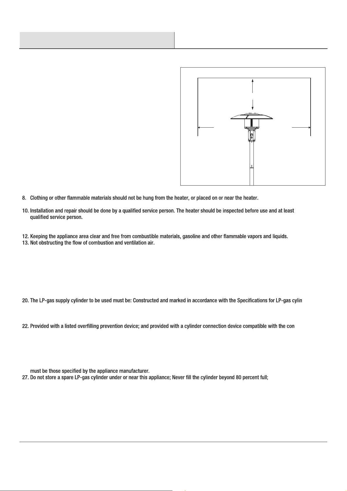
CEILING/OVERHANG
1. The installation must conform with local codes or, in the absence of
local codes, with the National Fuel Gas Code, ANSI Z223.1/NFPA 54,
NFPA58 Natural Gas and Propane Installation Code, CSA B149.1, or
Propane Storage and Handling Code, B149.2
2. The heater, when installed, must be electrically grounded in
accordance with local codes or, in the absence of local codes, with
the National Electrical Code, ANSI/NFPA 70, or the Canadian Electrical
Code, CSA C22.1.
3. Prior to use, check for damaged parts such as hoses, regulators, pilot
or burner.
4. All leak tests should be done with a soapy solution.NEVER USE AN
OPEN FLAME TO CHECK FOR LEAKAGE.
5. The propane hose with regulator assembly shall be located out of
pathways where people may trip over it or in areas where the hose
will not be subject to accidental damage.
6. Children and adults should be alerted to the hazards of high surface
temperatures and should stay away to avoid burns or clothing ignition.
7. Young children should be carefully supervised when they are in the
area of the heater.
36 in.
.ni63.ni63
Figure 1
WALL

MOC.YABNOTPMAH4
.ecnatsissarehtrufrofNOTPMAH-DH-558tcatnocesaelP
Pre-Assembly
PLANNING INSTALLATION
TOOLS REQUIRED
Adjustable Wrench Philips screwdriver
Before beginning assembly of product, make sure all parts are present.
If any part is missing or damaged, do not attempt to assemble the product.
Contact customer service for replacement parts.
HARDWARE
INCLUDED
NOTE: Hardware not shown to actual size.
Part Quantity
AA
AA
12
18BB
15
3
8
6
4
4
CC
DD
EE
FF
GG
HH
Description
NOTE: Tools are not included in the package.
BB
M6 x 10 Screw
D6 Washer
M6 Nut
M6 x 70 Double Pointed Bolt
M6 x 14 Bolt
M6 x 12 Flat Bolt
M6 x 14 Screw
M6 Locking Nut
CC
DD EE FF
GG HH
CP 65 Propane Warning
WARNING:
FUELS USED IN LIQUEFIED PROPANE GAS
APPLIANCES, AND THE PRODUCTS OF COMBUSTION OF SUCH
FUELS, CAN EXPOSE YOU TO CHEMICALS INCLUDING BENZENE,
WHICH IS KNOWN TO THE STATE OF CALIFORNIA TO CAUSE
CANCER AND CAUSE BIRTH DEFECTS OR OTHER REPRODUCTIVE
HARM.
For more information go to: www.P65Warnings.ca.gov.
ADVERTENCIA:
LOS COMBUSTIBLES USADOS EN EQUIPOS
PARA LICUAR GAS PROPANO, ASÍ COMO LOS PRODUCTOS DE SU
COMBUSTIÓN, PUEDEN EXPONERTE A SUSTANCIAS QUÍMICAS,
ENTRE ELLAS EL BENCENO, QUE EL ESTADO DE CALIFORNIA
RECONOCE COMO CAUSA DE CÁNCER Y DE MALFORMACIONES
CONGÉNITAS Y OTROS DAÑOS AL SISTEMA REPRODUCTOR.
Para más información, visite www.P65Warnings.ca.gov
Warranty
ONE-YEAR LIMITED WARRANTY
WHAT IS COVERED
We warrant to the original consumer/purchaser that all aspects of this product will be free of defects in material and workmanship for one year
from the date of purchase. A replacement for any defective part will be supplied free of charge for installation by the customer.
The warranty shall be effective from the date of purchase as shown in the purchaser’s receipt.
WHAT IS NOT COVERED
Defects or damage caused by the use of other than genuine parts are not covered by this warranty. We will not be responsible for labor charges
and/or damage incurred in installation, repair and replacement, nor for incidental or consequential damage. This warranty gives
rights, and you may also have other rights that vary from state to state.
The warranty is valid for the original consumer/purchase only and excludes industrial, commercial or business use of product, product damage
due to shipment or failure which results from alteration, product abuse, or product misuse, whether performed by a contractor, service
company, or consumer.
Contact the Customer Service Team at 855-HD-HAMPTON or visit www.hamptonbay.com.

5
Pre-Assembly (continued)
PACKAGE CONTENTS
CC
BB
AA
DD
EE
A
B
C
D
E
F
G
GG
HH
H
I
FF
EE
J
QuantityDescriptionPart
Center Reector Cap
Reector Shields
Burner Head
Upper Pole
Lower Pole
Decorative Cap
A
B
C
D
E
F
G
1
4
1
1
1
1
1
1
1
1
Base
H
I
J
Cylinder Locking Bar
Wheel
Knob

MOC.YABNOTPMAH6
.ecnatsissarehtrufrofNOTPMAH-DH-558tcatnocesaelP
Assembly
1Install Wheel 3Install Burner Head Assembly
Attach wheel (I) to the base (G) by with (4) M6x14 scres
(GG) & (4) M6 locking nuts (HH).
2Install Lower Pole
Attach lower pole (E) onto the base with (4) M6 x 14 bolts
(EE). Then slide the decorative cap (F) over the lower
pole (E) to cover the bolts.
Note: When you assemble lower pole to the base, please
4Install Upper Pole
Insert gas hose and regulator of the burner head (C) into
the lower pole (E).
Place the upper pole (D) on the lower pole (E) tighten with
Insert the hose & regulator of burner head (C) into upper
pole (D), then tighten the burner head (C) to the upper pole
(D) with (4) M6 x 14 bolts (EE).
Note: Make sure the regulator goes through the pole and
Align Instruction and Warning with control knob.
G
JC
D
C
GG
EE
HH
EE
F
G
E
Same direction
Same Direction
Same Direction
I
D
FF
F
Door

MOC.YABNOTPMAH7
.ecnatsissarehtrufrofNOTPMAH-DH-558tcatnocesaelP
Assembly (continued)
5 7
6Place Bolt
(AA), (12) 6mm washers (BB) and (12) M6 nuts (CC).
Thread (3) 6mm washers (BB) and (3) M6 x 70 double
pointed bolts(DD) into the burner head (C).
8Open the Door
head (C) and tighten with (3) 6mm washers (BB) and (3)
M6 nuts (CC).
BB
BB
DD
C
CC
CC
BB
AA
A
A
B
B
B
B

MOC.YABNOTPMAH8
.ecnatsissarehtrufrofNOTPMAH-DH-558tcatnocesaelP
Assembly (continued)
9Place Gas Cylinder 11 Close the Door
10 Install Regulator
Placethegas cylinder (not included) intothe base (G) and
secure with the cylinder locking bar (H).
Attach the regulator to the cylinder and turn
clockwise to securely tighten the valve. Close and
latch the door. Note: Make suretocheck for leaks
after attaching the cylinder. (For instructions, refer
to the page14-SAFETY CHECK) Toremove the
regulator, turn off the cylinder valve and turn
counterclockwise theregulator toloosen from the
cylinder.
12 Install Battery
Unscrew the battery compartment cap on thecontrol
panel, install one AAA battery (not included) with
anode end of battery located towards thebattery
compartment cap.
M
Tighten
gas hose and regulator
ignition button ignition button
AAA battery
(not included)

MOC.YABNOTPMAH9
.ecnatsissarehtrufrofNOTPMAH-DH-558tcatnocesaelP
Safety Check
hose
connection
brush
Check for leaks
All connection on the patio heater have been checked for leakageat the factory.
In transportation and handling some connections may have loosened.
Follow these steps to check the gas hose/regulator/cylinder connections:
1) Make leakage solution by mixing 1part liquid dish soap and 3 parts water.
2) Spoon or brush several drops (or use squirt bottle) of the solution ontohose
connection, regulator & cylinder connection.
3) Turn on gas cylinder valve. Inspect the connections and look for bubbles.
4) If nobubbles appear, the connection is safe.
5) If bubbles appear, there is leakage. Loosen and re-tighten thisconnection.
If connection still leaks, please call customer service:
Note:
1) The cylinder supply system must be arranged for vapor withdrawal;
2) The cylinder used must include a collar to protect the cylinder valve.
The hose assembly must be replaced prior to the appliance being put into
operation if there is evidence of excessive abrasion or wear, or if the hose
is damaged.
At least once a year, a complete inspection of the entire gas path
components should be performed.
If there is need to replace parts, proceed to leak test after reassembly
(These procedures should be performed by a professional technician).
regulator & cylinder
connection
WARNING : ONLY AN AUTHORIZED GAS TECHNICIAN SHOULD INSTALL THIS PRODUCT.
M5X10
WARNING: ONLY AN AUTHORIZED GAS TECHNICIAN SHOULD INSTALL
THIS PRODUCT. PROPER ASSEMBLY IS THE RESPONSIBILITY OF THE
INSTALLER.
Annual check operation:
a. Remove the observation window panel by un-screwing two bolts.
b.Turn on LP gas cylinder valve.
c. Spoon severla drops (or use squirt bottle) of the solution onto gas hose
connection and automatic valve connetion and the injector connection.
d. lnspect the connections and look for bubbles.
e. If nobubbles appear, the connection is safe.
f. Ifbubbles appear, there is a leak. Shut off the LPgas cylinder valve, loosen and
then re-tighten this connection.
g. Check for leaks again.
h. If bubbles still appear, close the LPgas cylinder valve and claa our customer
serviceline 1-866-814-0585. Do not attempt to use the heater.
i. Hose checking step:
(1) Unscrew M6 X 14 screw from the pole.
(2) Pull out the head assembly, hose & regulator from the pole.
(3) Check if there arecracks or worn sections on the hose. If yes, replace the
hose & regulator immediately.
(4) Check for leaks according to the above step by step after replacing the
hose & regulator.

FLAME CHARACTERISTIC
,
n the
is serviced
and or repaired.
OPERATION PRESSURE CHECKED:
RE-LIGHT:
1) Turn the control knob to "OFF " position.
3) Repeat steps beginning with step 3 of the lighting instruction.
SHUT DOWN INSTRUCTIONS:
1) Push in and turn control knob clockwise to "OFF" position.
2) Turn LP cylinder valve to "OFF" position.
THE EVENT OF GAS LEAKAGE:
Turn the control knob to "OFF" position.
Turn LP cylinder valve to "OFF" position
Wait 5 minutes to allow gas to dissipate.
If odor continues, immediately call gas supplier.
WARNING : Heater will be hot after use. Handle with extreme care.
01 MOC.YABNOTPMAH
.ecnatsissarehtrufrofNOTPMAH-DH-558tcatnocesaelP
Operation
LIGHTING INSTRUCTION
1. Turn the control knob to “OFF” position.
2. Turn LP cylinder gas valve to fully open position.
3. Push in gas control knob and turn counter-clockwise to "PILOT" position, at the
same time push in the ignition button and keep the button depressing until
light the pilot.
4. Once the pilot is lit, continue to keep the control knob depressed for at least 30
seconds, Then release control knob.
5. If pilot does not stay lit, repeat steps 3 and 4 after 5 minutes.
6. If pilot still does not stay lit, then:
a) Push in gas control knob and turn counter clockwise to the "PILOT" position.
b) keep depressing the control knob, put long stem lighter into the ignition hole
on the emitter screen to light the pilot.
c) Repeat step 4.
7. Push in and turn control knob counter clockwise to "HIGH" position, If you want
a lower temperature, push in the control knob and turn clockwise to the "LOW" position.

11 MOC.YABNOTPMAH
.ecnatsissarehtrufrofNOTPMAH-DH-558tcatnocesaelP
Maintenance
Care and Cleaning
Trouble Shooting
Turn the control knob to "OFF" position.
Turn LPcylinder to "OFF" position.
Store heater uprightin an area sheltered from direct contact with inclement weather (such asrain, sleet, hail, snow, dustanddebris).
If desired, cover heater to protect exterior surfaces and to help preventbuild up in air passages.
During periods of extended inactivity or when transporting;
Turn the control knob to "OFF" position.
Disconnect the regulator from the LP Cylinder by turning counter-clockwise and move to a secure, well-ventilated location outdoors.
DO NOT store in alocation that will exceed 125 degrees F.
Store heater uprightin an area sheltered from direct contact with inclement weather (such asrain, sleet, hail, snow, dustanddebris).
If desired, cover heater to protect exterior surfaces and to help preventbuild up in air passages.
Keep exterior surfaces clean.
While washing your unit, be sure to keep the area around the burner dry at all times. If the gas control is exposed to water in any way, do
NOT try to use it. It must be replaced.
of combustion and ventilation air; keeping the ventilation opening(s) of the cylinder enclosure free and clear from debris.
Screw down the screws on pole, take out the burner head assembly.
Check if there are cracks or worn sections on hose. If yes, please call our customer service to replace hose.
At least once a year, the unit should be inspected for the presence of spiders, spider webs or other insects.
2. Heater does NOT reach the desired temperature.
1. Gas odor with extreme yellow tipping of ame.
3. Heater glow is excessively uneven.
4. Heater makes popping noises.
an burner holes
by using a heavy-duty pipe cleaner. Compressed air may help clear away smaller particles.
Ignition will not stay on
no click voice when igniting
Burner will notlight
PROBLEM PROBABLE CAUSE SOLUTION
Pressure islow Fuel tankisnear empty
Turn valve toON
Contact customer service to get the component
Contact customer serviceto get the component
Contact customer service
try manual ignition; ifignited, please contact customer
service to get the component
try manual ignition; if still donot ignited, contact customer
service to return goods
control valve not ON
Thermocouplebroken
Thermocouplebroken
ignitor pin
valve broken
valve broken
valve broken

MOC.YABNOTPMAH21
.ecnatsissarehtrufrofNOTPMAH-DH-558tcatnocesaelP
Service Parts
MODEL TYPE
CC
BB
AA
DD
EE
A
B
C
D
E
F
G
GG
HH
H
I
FF
EE
J
QuantityDescriptionPart
Burner Head
Upper Pole
Lower Pole
Decorative Cap
A
B
C
D
E
F
G
1
4
1
1
1
1
1
1
1
1
Base
H
I
J
Cylinder Locking Bar
Wheel
Knob
AA BB CC
DD EE FF
GG HH

855-HD-HAMPTON
HAMPTONBAY.COM
Retain this manual for future use.
Questions, problems, missing parts? Before returning to your retailer,call our customer
service department 8 a.m. - 6 p.m., EST, Monday - Friday, 9 a.m. - 6 p.m., EST, Saturday.
Table of contents
Other HAMPTON BAY Patio Heater manuals

HAMPTON BAY
HAMPTON BAY PG139HDS User manual

HAMPTON BAY
HAMPTON BAY 68164 User manual

HAMPTON BAY
HAMPTON BAY PG171H-B User manual

HAMPTON BAY
HAMPTON BAY PG169T-B User manual

HAMPTON BAY
HAMPTON BAY HD10 User manual

HAMPTON BAY
HAMPTON BAY HDMIRAGECO PC User manual

HAMPTON BAY
HAMPTON BAY HDMIRAGECO PC User manual

HAMPTON BAY
HAMPTON BAY PH01-SS User manual