Handicare SIMPLICITY User manual

MANISSSIMML
INSTALLATION MANUAL • INSTALLATIEHANDLEIDING • INSTALLATIONSANLEITUNG
MANUEL D’INSTALLATION • MANUAL DE INSTALACIÓN • MANUALE DI INSTALLAZIONE
SIMPLICITY

2 HANDICARE SIMPLICITY INSTALLATION MANUAL
Pre-installation check list
1 Check that all of the required components
are available. You should have 6boxes.
These are colour coded so that identification
of any handed components is simple. The
table below shows the colour of the boxes
that you require.
COMPONENT Left hand Right hand
Footplate box PURPLE GREEN
Seat box
Power pack
BLACK
Fitting kit
Bottom track section
Top track section
e.g. a left hand lift comprises 2 purple and
4 black boxes; a right hand lift comprises
2 green and 4 black boxes.
2 Installation tools required
Note: The installation engineer must check
with Handicare for the latest installation
manual issue number.
• Loading toggle
• Shorting links
• 13mm Socket
• 17mm Socket
• 13mm Spanner
• Handlamp
• 2.5mm Allen key
• 3mm Allen key
• 4mm Allen key
• 5mm Allen key
• 6mm Allen key
• 8mm Allen key
• No. 2 Pozi-drive
• Spirit level
• Tape measure
• Hacksaw
• Tin snips
Handicare Simplicity
installation manual
Issue No of this manual is 0114-1
ORIGINAL LANGUAGE ENGLISH

HANDICARE SIMPLICITY INSTALLATION MANUAL 3
ENGLISH
Figure 1
Figure 2 Figure 3
Track assembly
Track assembly
Before beginning the installation please
ensure that the track is the required length.
Refer to Appendix 5 for details.
Items required: Tools required:
• Fit kit • 2.5mm Allen key
Splice bars x 3 • 3mm Allen key
Track ends cap x 1 • 6mm Allen key
Red bag • 13mm Spanner
8 x bolts • Hacksaw
4 x grub screws • Tin snips
Final limit stops x 1
End stops x 1
Mounting feet x 3
• Top track section x 1
• Bottom track section x 1
1 Position the bottom section of the track (2m)
on the stairs with the splice holes at the top
(Figure 1). Regardless of the hand of the lift
the rack should always be on the left hand
side of the track when looking up the stairs.
2 Bolt in the splice bars to the bottom section of
track extrusion (Figure 2) using 2 grub screws
for the top splice bar and the 4 bolts in the
bottom splice bars (from the red fittings bag).

4 HANDICARE SIMPLICITY INSTALLATION MANUAL
Figure 7Figure 5
Figure 4
Figure 6
Track assembly
Note: Ensure that the splice bars are positioned
in the track in the correct orientation. The splice
bar has three flat faces and one sloping face.
The sloping face MUST be positioned against
the sloping face on the extrusion (Figure 3).
3If the track is less than 2000mm and cutting
to length on site:
aRemove the charge spring contact
(Figure 4).
bUsing the loading tool, push the plastic
carrier strip up the top section of track
(Figure 5).

HANDICARE SIMPLICITY INSTALLATION MANUAL 5
ENGLISH
Figure 8
Figure 9
Figure 10
Track assembly
cAt the top end of the top section use a
hacksaw to remove the excess plastic
carrier strip (Figure 6).
dCarefully replace the charge spring contact.
4 Position the top section of track adjacent
to the bottom section of track (Figure 7).
5 Offer up the adjacent track section in the
normal way. Run the two core top safety
edge/end cap cable to the top of the track.
Bolt together the two track sections as normal.
6 Bolt both sections of track together (Figure 8).
The bolts should be tightened in sequence:
aleft bottom dleft top
bcentre bottom ecentre top
cright bottom fright top
Repeat this process until the bolts are all secure
(torque setting 8-9Nm).
7 Push the plastic carrier strip down from the
top track section to meet the plastic carrier
strip in the bottom section. The plastic carrier
strip will finish 10mm short of the end of the
track. Carefully feed down the copper charge
strip (Figure 9) and trim to the same length
as the plastic carrier strip.
8 Check that the charge strip has made proper
contact with the spring contact at the bottom
of the track (Figure 4).
Note: Ensure that the track is connected
with all faces level so that no step is present
in the joint.
Note: Excessive force can damage and
prevent the spring contact from making
a proper connection.
9Slide the three mounting feet on to the track
(Figure 10).
Note: See page 8 for Slide Track positioning.

6 HANDICARE SIMPLICITY INSTALLATION MANUAL
Figure 11
Figure 12
10 Position the feet in the following way
(Figure 11):
aThe top foot should be positioned on the
last tread.
bThe middle foot should be positioned
immediately next to the spliced joint. If the
top section is longer than the bottom then
the foot should be ABOVE the spliced joint,
if not, then the foot should be BELOW the
spliced joint.
cThe bottom foot should be positioned on
the first tread.
11 Loosely tighten the feet to stop them from
moving. The feet will help to stop the track
from moving on the stairs while the next
steps are performed.
Note: If the stairlift is being fitted to a staircase
with open bannisters on the bannister side
they must be covered with a solid sheet
material for safety.
12 If the power supply is:
aAt the top of the track:
• Feed the long power cable with the push
terminals from the power supply through
the large cavity in the assembled track.
bAt the bottom of the track:
• Bring the long power cable with the push
terminals from the power supply to the
bottom of the track.
13 Slide the track up the stairs and position it
centrally to give you sufficient room to work
comfortably at the bottom of the stairs.
14 Connect the positive push terminal (WHITE
CABLE) to the red push terminal attached
to the busbar (Figure 12).
15 Connect the negative push terminal (BLACK
CABLE) to the push terminal from the track.
16 Fit the bottom end stop and final limit stop
to the bottom of the track only (Figure 13).
Track assembly

HANDICARE SIMPLICITY INSTALLATION MANUAL 7
ENGLISH
Figure 13
Figure 14
Note: The shorter (square ended stop)
must be fitted in the top channel – failure
to do this correctly could damage the lift.
17 Fit the bottom end cap to the track
(Figure 14), ensuring that the power supply
cable is fed through the channel provided
so that it exits the track on the WALL side.
18 Tighten the grub screws to secure the end
cap to the track.
Note: The grub screws on the end cap
should not be over tightened.
19 Now slide the bottom end stop and final limit
stop so that they sit against the positioning
extensions of the end cap and then tighten
the grub screws (Figure 14).
Track assembly

8 HANDICARE SIMPLICITY INSTALLATION MANUAL
Figure 17
Figure 16
Figure 15
Feet positioning
Second foot
Splice
Third/
last foot
Feet positioning
Items required: Tools required:
• None • 13mm Spanner
• 13mm Socket
1 Slide the track to the side of the stairs that
it will be finally located to position the feet.
The feet should be positioned so that they
are touching the stringer (Figure 15).
Note: If the stringer does not extend to the
tread, i.e. it overhangs the staircase, use a
plumb line to mark a position on the stairs.
The feet should all be positioned in this way.

HANDICARE SIMPLICITY INSTALLATION MANUAL 9
ENGLISH
Figure 18
Figure 19
Figure 20
2 With the end of the track positioned so that
it is just touching the floor ensure that the
feet are still positioned on the stair treads
as previously described (Figure 11), i.e:
aThe top foot should be positioned on
the last tread.
bThe middle foot should be positioned
immediately above the spliced joint.
cThe bottom foot should be positioned
on the first tread.
3 Tighten the bolts on the feet (Figure 16).
Slide Track only
4 Position the first (fixed) foot on the second
step of the staircase. Then position and
loosely fix the second foot to the stairs,
two full steps below the track splice point
(or the end of the track for a single section
track), to allow clearance when the Slide
Track moves (Figure 17). The track should
be approximately 25mm from the nose of
the stairs.
5 Position the remaining feet on the steps and
loosely fix them to the stairs. The last foot
needs to be positioned two full steps down
from the top of the stairs, whilst the third foot
should be as close as possible to the splice.
6 The feet should sit as close as possible to the
stringer (Figure 18).
Note: Track may need to be moved out
to ensure seat clears.
7 If the track was not delivered pre-cut to
the correct length, trim the communications
busbar to the appropriate length to
accommodate the top end cap (Figures
4, 5 and 19).
8 Clip on the stringer-side roller covers using
the tacks provided. Then, with the track in
approximately the correct position, put a
screw into each foot to stabilise the track
(Figure 20).
Feet positioning

10 HANDICARE SIMPLICITY INSTALLATION MANUAL
Figure 21
Figure 22
Loading the power pack
Items required: Tools required:
• Power pack • Loading toggle
• Fit Kit • Shorting links
End cap x 1
Green bag
Wood screws x 12
Final limit stops x 1
End stops x 1
Busbar pickup loading tool
(x 2 for Slide Track)
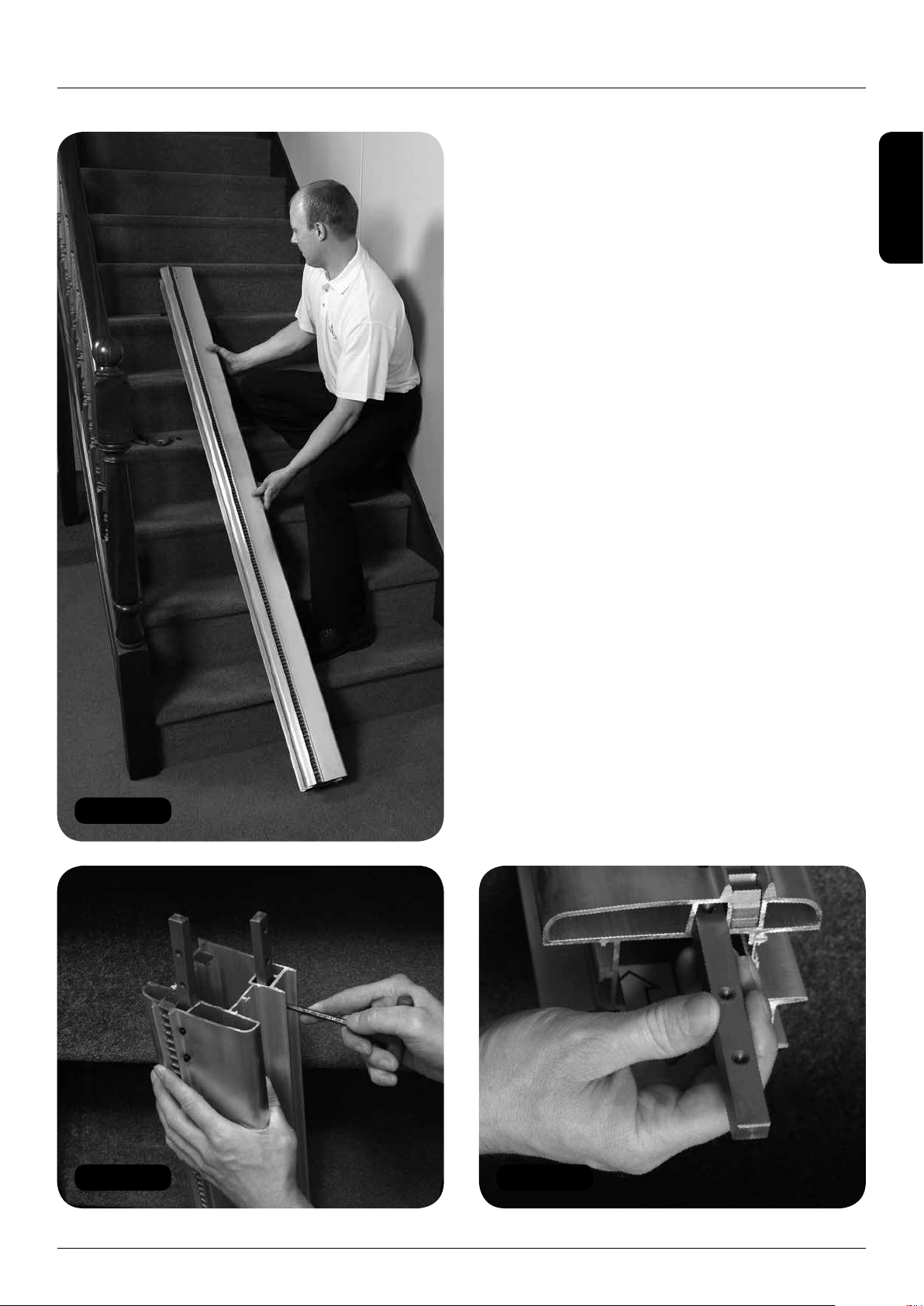
1 Carry the power pack box to the top of the
stairs.
2 Unpack the power pack from its box carefully.
3 Move the track away from the stringer slightly,
around 150mm, to give you more room to
work.
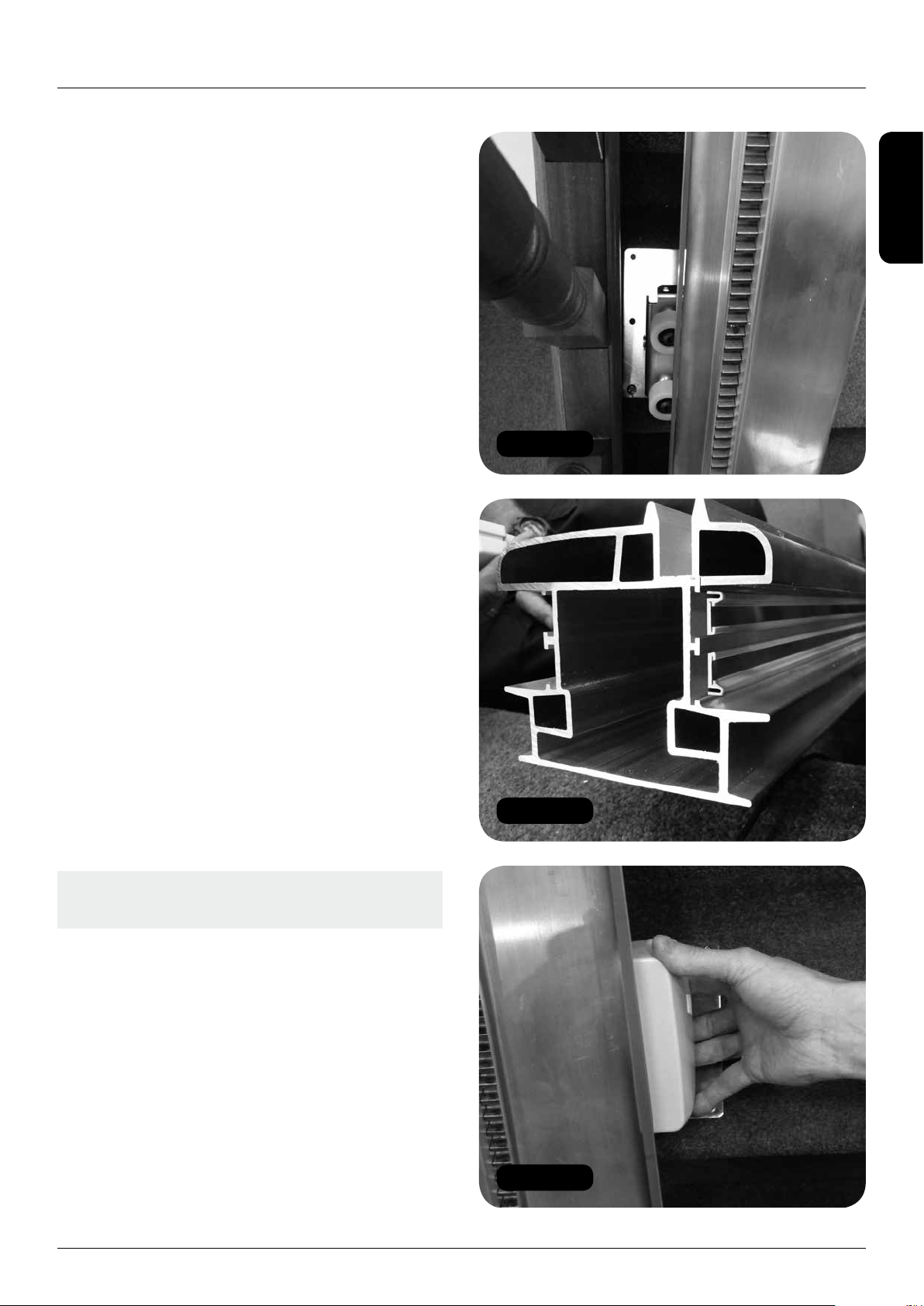
4 Remove the blanking plates from the side of
the power pack that will be facing the stairs
(Figure 22).
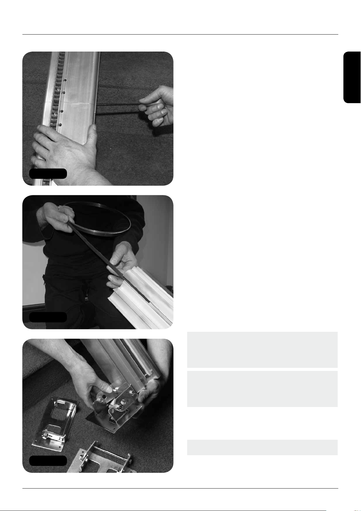
5 Connect the limit switch shorting links
(Figures 21 and 22).
6 Connect the driving links (or loading toggle)
(Figures 21 and 22).
7 Ensure that the busbar pickup loading tool
is correctly positioned (Figure 23).
8 Carefully slide the power pack onto the track
until the drive pinion meets the beginning of
the rack (Figure 24).
9 Turn the power pack on from the main switch
on the lower safety edge (Figure 25).
10 Using the loading driving links or toggle
switch (Figure 26), drive the power pack
onto the track. The power pack should be
driven to a position approximately half way
between the top and middle foot.
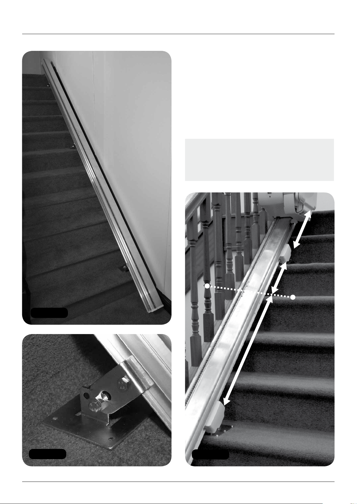
11 Fit the top end stop and final limit stop to the
top of the track (Figure 27).
Note: The shorter (square ended stop) must
be fitted in the top channel – failure to do
this correctly could damage the lift.
12 Fit the top end cap to the track and tighten
the grub screws to secure it.
Note: The grub screws on the end cap should
not be over tightened. If the power supply
is being connected at the top of the stairs,
ensure that the power supply cable is fed
through the channel provided so that it exits
the track on the WALL side.
13 Now slide the top end stop and final limit
stop so that they sit against the positioning
extensions of the end cap and then tighten
the grub screws.

HANDICARE SIMPLICITY INSTALLATION MANUAL 11
ENGLISH
Figure 24
Figure 25
Figure 27
Figure 28
Figure 26Figure 23
Loading the power pack

12 HANDICARE SIMPLICITY INSTALLATION MANUAL
Figure 30
Figure 31
Figure 29
Note: The final limit stop jacking screw
should only be used if the final limit is not
being recognised when the pack is run on the
track. Tighten one full turn max after contact
(Figure 28).
Slide Track installations
14 When loading the pack take care to correctly
position the two busbar pickup loading tools
(Figure 29).
15 In order to load the pack dipswitch 2 on the
main PCB must be set to the OFF position.
Once loaded this dipswitch should be
returned to the ON position to enable the
Slide Track (see wiring diagrams).
Note: Do not drive the power pack in the UP
direction until the top end cap has been fitted.
The busbar may move and lose contact with
the spring at the bottom of the track.
16 Connect the power supply to the ring main or
fused spur. A 400mm long “lazy loop” must
be left by the stringer near the point under
the centre of the track where the power cable
enters the track. This is to allow slack for the
Slide Track’s travel (Figure 30).
17 Connect the top track safety edge assembly
(active end cap) remembering to attach the
additional wires (Figure 31).
Loading the power pack

HANDICARE SIMPLICITY INSTALLATION MANUAL 13
ENGLISH
Figure 33
Figure 34
Figure 32
Items required:
• Footplate
Tools required:
• 6mm Allen key
• Spirit level
Fitting the footplate
1Drive the power pack, using the loading
toggle, to around the second or third step
so that it is at a comfortable working height
for fitting the footplate.
2 Position the ‘top hat’ on to the power pack
(Figure 32).
3 Insert the one bolt through the stair side
slotted hole in the footplate chassis and
then position the spacer supplied (Figure 33),
ensuring that the top hat locates into the
hole on the footplate chassis below the
slotted holes.
4 Loosely tighten the bolt to the power pack
chassis.
5 Repeat steps 3 and 4 in the other slotted hole.
Note: Only fit one bolt at a time. Trying to do
two together is very difficult.
6 Loosely fit the safety bolt (Figure 34).
Fitting the footplate

14 HANDICARE SIMPLICITY INSTALLATION MANUAL
Figure 36
Figure 37
Figure 35
7 Place a spirit level on the footplate and tap
the footplate chassis to level it (Figure 35).
8 Fully tighten the two footplate bolts.
9 Tighten the safety bolt until it just ‘bites’
on to the power pack chassis.
Note: Over tightening the safety bolt will twist
the footplate chassis.
10 Disconnect the shorting links and connect
the footplate cables to the power pack cables
(Figures 36 and 37).
Fitting the footplate

HANDICARE SIMPLICITY INSTALLATION MANUAL 15
ENGLISH
Figure 39
Figure 40
Figure 38
Figure 41
Items required:
• Seat
Tools required:
• 17mm Socket
• 8mm Allen key
• 4mm Allen key
• No. 2 Pozi-drive
Fitting the seat
1 Remove the seat and the seat post from
the seat box.
2 Remove the nuts from the seat bolts in the
seat post (Figure 38).
3 Fit the spacers to the seat bolts (Figure 39).
4 Bolt the seat post to the power pack
(Figure 40).
Note: If you fit the seat post to the power
pack in the configuration that it is delivered,
the seat to footplate height will be 390mm.
The seat post can be extended by sliding
the outer sleeve upwards. Each interval is
20mm up to a maximum of 490mm. If you
know the seat to footplate height that the
client requires, adjust the seat post to the
appropriate setting before bolting it to the
power pack chassis.
5 Fit the safety bolt (Figure 41).
Fitting the seat

16 HANDICARE SIMPLICITY INSTALLATION MANUAL
Figure 43
Figure 42
Note: Do not fully tighten any of the seat
bolts at this stage as the seat has not yet
been levelled.
6 Lay the seat on its back on the floor and
remove the seat base bolt and washer
(Figure 42).
7 Lift the seat (Figure 43) and position it on
to the seat stem.
8 Gently rotate the seat backwards and
forwards until the swivel locking peg locates.
9 Fully swivel the seat using the swivel levers.
10 Re-fit the seat base bolt and washer that you
removed in step 6 (Figure 44).
11 Swivel the seat back to the drive position
using the swivel levers.
12 Remove the drive toggle and link cables and
make the seat cable connections (Figure 45).
13 Fit the footplate chassis cover (Figure 46),
ensuring that all cables are positioned within
the cover.
Note: Ensure that no cables are pinched
or trapped when fitting the footplate
chassis cover.
14 Re-position the track as previously described
on page 8 with the feet against the stringer.
Fitting the seat

HANDICARE SIMPLICITY INSTALLATION MANUAL 17
ENGLISH
Figure 44
Figure 45
Figure 46
Fitting the seat

18 HANDICARE SIMPLICITY INSTALLATION MANUAL
Figure 47 Figure 48
Figure 49
Figure 50
Figure 51
Securing the track
1 Drive the power pack up and down the
stairs to ensure that it will not encounter any
unforeseen obstacles (Figures 47 and 48).
Note: Look for any other potential obstacles
such as window ledges or exposed pipework
that could obstruct the movement of the lift at
this stage.
Items required:
• Fit kit
Green bag
Woodscrews
Tools required:
• Spirit level
• Tape measure
• No. 2 Pozi-drive
Securing the track

HANDICARE SIMPLICITY INSTALLATION MANUAL 19
ENGLISH
Figure 52
Securing the track
Note: If there are any other obstacles move
the track away from the wall until the rear edge
of the power pack can travel freely past them.
2 Drive the stairlift to the top of the track.
If the footplate does NOT finish level with
the landing then:
aDrive the stairlift so that the footplate is level
with the top of the stairs (Figure 49).
bMeasure the distance from the top safety
edge to the inside face of the end cap
(Figure 50).
cDrive the stairlift halfway down the stairs.
dCarefully slide the top of the track into the
middle of the staircase so that you have
access to the end stops (you may not need
to do this if you are installing a left hand lift).
eLoosen the grub screws on the bottom stop
(the ramped one) so that you can just slide it.
Note: Be careful not to loosen the grub
screws fully – the bottom stop may slide
all the way down the track.
fSlide the bottom stop down the track
so that the distance from the top edge
of the stop to the inside face of the end cap
is the same as the distance measured from
the safety edge to the end cap (Figure 51).
gTighten the grub screws.
hRe-position the track in its final location as
previously described.
i Drive the stairlift back to the top of the stairs
and check that the footplate now finishes
level with the landing (Figure 49).
jMake minor adjustments as necessary and
repeat process until the footplate finishes
level with the landing.
3 Secure the feet to the staircase using the
woodscrews provided in the Green bag
from the fit kit (Figure 52).
Note: If you are installing the Simplicity track
on onto a carpet that is very thick and is
liable to compress significantly under load
you MUST space the track 10mm from the
nose of the staircase. Failure to do so may
result in the footplate safety edge operating,
stopping the lift.
4 Fit the power supply to the wall in an
appropriate position using the bracket
supplied.

20 HANDICARE SIMPLICITY INSTALLATION MANUAL
Figure 53
Figure 54
Items required:
• Handsets
Tools required:
• No. 2 Pozi-drive
• 5mm Allen key
Remote control handsets
Programming
The infra-red remote control handsets supplied
with the lift should work out of the box. If the lift
does not travel up and down the stairs when the
corresponding handset buttons are pressed, or
if there are multiple lifts in one area, follow the
procedure set out below.
1 Drive the lift to the third or fourth step so that
it is at a comfortable height to work on.
2 Remove the bottom safety edge by undoing
the two visible cross head screws on the top
edge and the one hidden Allen by the track
(Figure 53).
3 Slide the bottom safety edge down the track
to expose the control board and batteries.
4 Bring both handsets to the lift and then
programme the handset to the board in the
following way.
aFor single lift applications:
iPress and hold the red button on the
PCB (Figure 54) – a yellow LED will
illuminate on the PCB.
ii Press any button on the handset
and the yellow light will go out.
iii Programming is complete.
Note: Low energy light bulbs can interfere
with the infrared signal causing the lift to stop
and start. Reprogramming the handsets with
the lights on can resolve this problem.
Remote control handsets
Table of contents
Languages:
Other Handicare Stairlift manuals

Handicare
Handicare 2000 User manual

Handicare
Handicare 2000 User manual

Handicare
Handicare Minivator 1000 series User manual

Handicare
Handicare 1100 User manual

Handicare
Handicare Simplicity+ User manual

Handicare
Handicare Xclusive User manual

Handicare
Handicare Simplicity+ User manual

Handicare
Handicare Freecurve Classic User manual

Handicare
Handicare 1100 User manual

Handicare
Handicare 2000 User manual