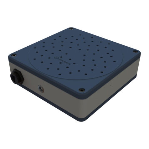
HBK GEN7iB GEN Series User manual

English
User Manual
GEN series GEN7iB
Desktop and Rack Mount
Tethered Data Acquisition System

GEN7iB
2IMPRINT
IMPRINT
Document version 1.1 - June 2023
References made to the Perception software are for version 7.40 or higher
For HBK's Terms and Conditions visit www.hbm.com/terms
Hottinger Brüel & Kjaer GmbH
Im Tiefen See 45
64293 Darmstadt
Germany
Tel: +49 6151 80 30
Fax: +49 6151 8039100
Email: [email protected]
www.hbm.com/highspeed
Copyright © 2023
All rights reserved. No part of the contents of this document may be reproduced or transmitted in
any form or by any means without the written permission of the publisher.

GEN7iB
LICENSE AGREEMENT AND WARRANTY 3
LICENSE AGREEMENT AND WARRANTY
LICENSE AGREEMENT and WARRANTY
For information about LICENSE AGREEMENT AND WARRANTY refer to:
www.hbm.com/terms.
Trademarks and patents
StatStream®is a registered trademark of HBK in the European Union and a trademark
in other countries.
StatStream® is patented in the US, Patent No. 7,868,886; patent pending in other
countries.
Legal statement
This product uses GNU General Public Licensed (GPL) software, the source code is
available at:
www.hbm.com/highspeed
For more information please refer to the following website:
www.gnu.org
LICENSE AGREEMENT AND WARRANTY

GEN7iB
4TABLE OF CONTENTS
TABLE OF CONTENTS
ToC - Overview
About this manual ......................................................13
1.1 Symbols used in this manual ........................................ 13
1.2 Manual conventions................................................ 14
2 Safety Messages ................................................15
2.1 Introduction....................................................... 15
2.2 Grounding ........................................................ 18
2.2.1 Mains power cord .................................................. 19
2.3 Instrument Symbols................................................ 20
2.4 Protection and isolation............................................. 21
2.4.1 Measurement categories............................................ 21
2.4.2 Basic insulation versus reinforced .................................... 23
2.4.3 Protection ........................................................ 25
2.4.4 Overvoltage/current protection....................................... 26
2.4.5 Isolation .......................................................... 26
2.5 Environment ...................................................... 27
2.6 Laser Safety....................................................... 28
2.7 Manual handling of loads ........................................... 29
2.8 International safety warnings ........................................ 30
2.9 Operation of electrical installations ................................... 46
3 Normative Documents and Declarations..............................47
3.1 Electrical ......................................................... 47
3.1.1 Electrostatic Discharge (ESD)........................................ 47
3.1.2 Electromagnetic Compatibility (EMC) ................................. 48
3.2 Environment ...................................................... 50
3.2.1 RoHS and WEEE - Waste Electrical and Electronic Equipment ............. 50
3.2.2 China RoHS ....................................................... 51
3.3 CE and UKCA Declaration of conformity ............................... 52
3.3.1 CE Declaration of conformity ........................................ 52
3.3.2 UKCA Declaration of conformity...................................... 52
3.4 FCC Class A Notice................................................. 53
4 Batteries .......................................................54
4.1 General........................................................... 54
4.2 Removal and replacement........................................... 55
4.3 Recharging ....................................................... 58
4.4 Disposal .......................................................... 59

GEN7iB 5
TABLE OF CONTENTS
TABLE OF CONTENTS
5 Mains Power ....................................................60
5.1 Power and frequency requirements ................................... 60
5.2 Connecting power.................................................. 61
5.3 Fuse requirements and protection .................................... 63
5.4 Fuse replacement .................................................. 64
6 Introduction.....................................................66
6.1 Introducing GEN7iB ................................................ 66
6.2 Mainframe overview................................................ 67
6.2.1 Mainframe feature comparison ...................................... 68
6.3 Hardware ......................................................... 69
6.3.1 PCI-e/CPCI backplane .............................................. 69
6.3.2 Input cards........................................................ 70
6.3.3 Master/Sync support ............................................... 70
6.3.4 Thermal protection ................................................. 70
6.4 Acquisition........................................................ 72
6.4.1 StatStream ....................................................... 73
6.5 Signal conditioning................................................. 74
6.6 Data storage ...................................................... 75
6.7 PC Section ........................................................ 76
6.8 Perception Software................................................ 77
6.8.1 Windows®logon password and remote desktop access.................. 77
6.9 Perception language settings ........................................ 78
7 Setting up the GEN7iB ............................................80
7.1 PC connections.................................................... 80
7.1.1 USB 3.0 and USB 2.0 ports .......................................... 82
7.1.2 Mini DisplayPorts .................................................. 82
7.1.3 Sound ............................................................ 82
7.1.4 Removable drive bay ............................................... 83
7.2 Removing and installing input cards .................................. 87
7.2.1 Removing cards ................................................... 87
7.2.2 Installing cards ..................................................88
7.3 Handle ........................................................... 90
7.3.1 Turning the handle ................................................. 91
7.4 Feet.............................................................. 92
7.4.1 To turn the feet out: ................................................ 92
7.4.2 To turn the feet in:.................................................. 92
7.5 Probe calibration................................................... 93

GEN7iB
6TABLE OF CONTENTS
TABLE OF CONTENTS
7.6 DC power output ................................................... 95
7.7 Digital Event/Timer/Counter ......................................... 97
7.7.1 Isolated event adapter ............................................. 101
7.7.2 Torque/RPM adapter .............................................. 102
7.7.3 eAxle setup ...................................................... 104
7.8 Accessing the CPU section ......................................... 105
7.9 Airlterreplacement .............................................. 110
8 Getting Started .................................................112
8.1 Front panel control ................................................ 112
8.2 Getting started ................................................... 114
9 Acquisition and Storage ..........................................115
9.1 Introduction...................................................... 115
9.1.1 The basic ideas behind Acquisition Modes in Perception V7 and V8 ...... 115
9.1.2 Terminology...................................................... 119
9.2 Acquistion Modes - User Interface ................................... 120
9.3 Setup for the Acquisition Modes .................................... 123
9.3.1 On start of acquisition ............................................. 123
9.3.2 Wait for trigger ................................................... 125
9.3.3 Waitfortriggertotriggermemoryrst ............................... 127
9.3.4 Onstartofacquisitionreducedrateandwaitfortriggertotriggermemoryrst
130
10 Digital Trigger Modes ............................................132
10.1 Introduction...................................................... 132
10.2 Understanding digital triggering ..................................... 133
10.2.1 Digital trigger detector ............................................. 133
10.2.2 Valid trigger conditions ............................................ 134
10.3 Trigger modes .................................................... 136
10.3.1 Basic trigger mode ................................................ 136
10.3.2 Dual trigger mode ................................................. 137
10.3.3 Triggerqualier ................................................... 138
10.4 Recorder and system trigger........................................ 139
10.5 Channel alarm .................................................... 140
11 Interface/Controller .............................................141
11.1 Introduction...................................................... 141
11.2 Communication and control ........................................ 142
11.2.1 Network protocols and ports........................................ 143
11.2.2 Using the 1 Gbit option connections ................................. 144

GEN7iB 7
TABLE OF CONTENTS
TABLE OF CONTENTS
11.3 Master/Sync connector ............................................ 145
11.3.1 Connecting the Master/Sync connector .............................. 149
11.3.2 Connecting multiple mainframes using the Master/Sync card ........... 150
11.3.3 Setting the Master/Sync operating modes ............................ 152
11.3.4 Synchronizing a Master/Sync setup to external time sources............ 154
11.4 I/O connector .................................................... 155
11.4.1 I/O connector input overvoltage protection ........................... 156
11.4.2 I/O connector functions and connector pinning........................ 157
11.4.3 External Start In/External Stop In.................................... 159
11.4.4 External Event In use with RT-FDB ................................... 161
11.5 Option - Removable Solid State Drive (SSD) ........................... 162
11.6 Option - Optical 1 Gbit Ethernet interface ............................. 164
11.7 Option - 10 Gbit Ethernet interface (SFP+ Module) ..................... 166
11.7.1 Installing a 1 Gbit SFP/10 Gbit SFP+ Module .......................... 173
11.7.2 Removing a 1 Gbit SFP/10 Gbit SFP+ Module ......................... 178
12 Input Cards ....................................................179
12.1 Available input cards .............................................. 179
12.2 GN310B (2 MS/s), GN311B (200kS/s) Power Analyzer input cards........ 182
12.2.1 Measuring voltages ............................................... 183
12.2.2 Connecting3-phaseArticialStarAdapter ............................ 187
12.2.3 Measuring currents ............................................... 189
12.2.4 Connecting HBM current transducers ................................ 193
12.2.5 Connecting LEM current transducers ................................ 194
12.2.6 Understanding the GN310B/GN311B category rating ................... 195
12.2.7 Understanding the GN310B/GN311B high voltage input ................ 197
12.2.8 GN310B/GN311B Isolation Voltage channel........................... 198
12.2.9 GN310B/GN311B Isolation Current channel ........................... 203
12.2.10 GN310B/GN311B type testing of the HV channels ..................... 204
12.3 Isolated 1kV input cards ........................................... 209
12.3.1 GN610B, Isolated 1kV 2MS/s input card with real-time formula database.. 209
12.3.2 GN611B, Isolated 1kV 200kS/s input card with real-time formula database 210
12.3.3 Using the GN610B/GN611B ........................................ 211
12.3.4 Understanding the GN610B/GN611B category rating ................... 215
12.3.5 Understanding the GN610B/GN611B input............................ 216
12.3.6 Using the High Precision Differential Probe ........................... 218
12.3.7 Measuring currents ............................................... 220
12.3.8 GN610B/GN611B Isolation and type testing........................... 221
12.3.9 GN610B/GN611B protection mechanisms ............................ 230

GEN7iB
8TABLE OF CONTENTS
TABLE OF CONTENTS
12.4 Isolated Basic/IEPE cards .......................................... 235
12.4.1 GN815, Isolated Basic/IEPE 2MS/s input card ......................... 235
12.4.2 GN816, Isolated Basic/IEPE 200kS/s input card ....................... 236
12.4.3 Using the GN815 and GN816 ....................................... 237
12.4.4 Understanding the GN815 and GN816 isolation........................ 239
12.4.5 Understanding the GN815 and GN816 input........................... 240
12.4.6 GN815 and GN816 Input overload protection .......................... 242
12.5 Basic high speed input card ........................................ 245
12.5.1 GN8101B/GN8102B/GN8103B, Basic 250, 100, 25 M/s input cards ....... 245
12.6 High resolution universal input card ................................. 246
12.6.1 GN840/GN1640 Universal 500 kS/s 8/16 channel input cards ........... 246
12.6.2 Basic mode and cabling............................................ 248
12.6.3 Bridge mode and cabling ........................................... 249
12.6.4 Basic sensor and cabling........................................... 253
12.6.5 Integrated Electronic Piezoelectric (IEPE) mode and cabling............. 254
12.6.6 Piezoelectric (Charge) mode and cabling ............................. 255
12.6.7 Resistive Temperature Detectors (RTD) mode and cabling. . . . . . . . . . . . . . . 256
12.6.8 Resistance mode ................................................. 257
12.6.9 Current loop mode and cabling...................................... 260
12.6.10 Thermocouple mode and cabling .................................... 261
12.6.11 DIN rail breakout .................................................. 262
12.6.12 Flexible wiring .................................................... 265
12.7 Opticalberisolatedinputcard ..................................... 266
12.7.1 GN1202B,Opticalberisolated100MS/sinputcard ................... 266
12.8 High resolution IEPE and Charge input cards .......................... 268
12.8.1 GN3210 IEPE and charge 250 kS/s input card ......................... 268
12.8.2 GN3211 basic 20 kS/s input card.................................... 270
13 Option Cards ...................................................272
13.1 Option Carrier Card (OCC) .......................................... 272
13.1.1 Option cards supported ............................................ 273
14 GEN series Synchronization Methods ...............................274
14.1 GEN series synchronization methods compared ....................... 274
14.1.1 Signal phase shift synchronization .................................. 274
14.1.2 Trigger synchronization ............................................ 276
14.1.3 Absolute time of day synchronization ................................ 277
14.1.4 Start/Stop synchronization ......................................... 279
14.1.5 Synchronizationspecicationoverview .............................. 280

GEN7iB 9
TABLE OF CONTENTS
TABLE OF CONTENTS
14.2 PTP ............................................................. 282
14.2.1 PTP(1) technology background ...................................... 282
14.2.2 PTP Protocol details............................................... 283
14.2.3 Best master clock algorithm (BMC) .................................. 284
14.2.4 PTP switch types ................................................. 286
14.2.5 Transparent clock switch synchronization ............................ 290
14.2.6 Common terms used in IEEE 1588 ................................... 294
14.2.7 PTP and Master/Sync ............................................. 295
14.3 GPS............................................................. 297
14.3.1 Installation....................................................... 297
14.3.2 Using the GPS antenna ............................................ 299
14.3.3 Setup comparison ................................................ 315
14.3.4 GPS antenna placement ........................................... 316
14.3.5 GPS antenna lightning protection. . . . . . . . . . . . . . . . . . . . . . . . . . . . . . . . . . . . 318
14.3.6 Trouble-shooting guide for G002B ................................... 318
14.4 IRIG............................................................. 319
14.4.1 System overview.................................................. 319
14.4.2 Installation....................................................... 322
14.4.3 Using the GMR1000 module ........................................ 323
14.4.4 Trouble-shooting guide for G001B ................................... 330
15 Understanding Inputs and Usage of Probes ..........................331
15.1 GEN series inputs ................................................. 331
15.1.1 Single-ended input ................................................ 332
15.1.2 Balanced differential input ......................................... 334
15.1.3 Isolated single-ended or Isolated unbalanced differential input........... 335
15.1.4 Isolated balanced differential input .................................. 337
15.2 GEN series voltage probe types ..................................... 339
15.2.1 Passive, single-ended voltage probes ................................ 340
15.2.2 Passive, single-ended isolated voltage probes ......................... 342
15.2.3 Passive, differential matched isolated voltage probes .................. 343
15.2.4 Active differential voltage probes.................................... 344
15.3 Probe bandwidth calibration ........................................ 345
15.3.1 1X Probes ....................................................... 345
15.3.2 10X Probes ...................................................... 347
15.3.3 Probes and differential measurements ............................... 348
15.4 Current shunt measurements ....................................... 349
A Real-time Formula Database Calculators ............................350

GEN7iB
10 TABLE OF CONTENTS
TABLE OF CONTENTS
A.1 Overview ........................................................ 350
B Maintenance ...................................................354
B.1 Preventive maintenance ........................................... 354
B.2 Preventive drive replacement ....................................... 355
B.2.1 Hard disk drive ................................................... 355
B.2.2 Solid State Drive (SSD)............................................. 355
B.3 Preventiveairlterreplacement ..................................... 356
B.4 Cleaning ......................................................... 357
B.5 Cleaning and disinfecting the touch screen ........................... 358
B.5.1 Cleaning the touch screen.......................................... 358
B.5.2 Disinfecting the touch screen ....................................... 358
B.5.3 US CDC-recommended disinfectant solutions safe for touch screen ...... 359
C Service Information .............................................361
C.1 General - Service Information ....................................... 361
C.2 Calibration/verication ............................................ 362
D Trouble-shooting ...............................................363
D.1 Boot setup ....................................................... 363
D.2 GHS Integrated system image restore................................ 367
D.2.1 Boot menu preparation ............................................ 367
D.2.2 Starting image restore ............................................. 369
D.2.3 Image restore phase 1 - Installing devices ............................ 372
D.2.4 Image restore phase 2 - Measuring video performance ................. 372
D.2.5 Image restore phase 3 - Windows 10 welcome......................... 373
D.2.6 Potential problems after restore..................................... 380
D.3 Touch screen calibration ........................................... 383
D.3.1 ELO touch screen ................................................. 384
D.4 Backing up the recovery partition.................................... 388
D.5 Recovery partition creation ........................................ 391
D.5.1 Using the Integrated System Recovery USB Disk....................... 391
D.5.2 Starting recovery partition creation .................................. 392
D.5.3 Starting recovery partition restore ................................... 393
D.6 GHS Integrated system BIOS update ................................. 396
D.7 Language settings in Windows...................................... 398
D.7.1 How to change the Windows®10 display language..................... 398
D.7.2 Installing a Language Pack in Windows 10............................ 401
D.8 Embedded Software upgrades ...................................... 410
D.8.1 Boot recovery switch .............................................. 410

GEN7iB 11
TABLE OF CONTENTS
TABLE OF CONTENTS
D.9 Unexpected mainframe shutdown ................................... 413
D.10 The Master/Sync connection does not synchronize .................... 414
D.11 Optical Network (SFP) ............................................. 415
D.12 Master/Syncconnectionvericationprocedure........................ 416
D.13 IRIG GMR1000 Trouble-shooting .................................... 418
D.14 GPS OTMC 100 Trouble-shooting .................................... 443
D.15 Diagnostics web page interface ..................................... 464
E Frequently Asked Questions ......................................465
E.1 Overview ........................................................ 465
F Rack Mount Instructions .........................................466
F.1 Mount GEN7iB in a 19-inch rack ..................................... 466
G PTP Synchronization ............................................468
G.1 Mainframe PTP connections........................................ 468
G.1.1 GEN7i ........................................................... 468
G.1.2 GEN7iA/GEN7iB .................................................. 469
G.1.3 GEN7tA/GEN7tB .................................................. 470
G.1.4 GEN2tB.......................................................... 471
G.1.5 GEN4tB.......................................................... 472
G.1.6 GEN3i ........................................................... 473
G.1.7 GEN3iA.......................................................... 474
G.1.8 GEN17tA/GEN17B ................................................ 475
G.2 Perception settings ............................................... 476
G.3 Synchronizing GEN series and QuantumX using PTP ................... 477
G.3.1 GEN3i with single QuantumX "B" version module....................... 477
G.3.2 GEN3i with single SomatXR "B" version module........................ 478
G.3.3 GEN3i with up to three QuantumX "B" version modules ................. 479
G.3.4 GEN3i with standard network switch and four or more of QuantumX "B" version
modules......................................................... 481
G.3.5 GEN3i with PTP network switch and four or more of QuantumX "B" version
modules......................................................... 483
G.3.6 GEN7tA/GEN7tB with multiple QuantumX "B" version modules ........... 485
G.3.7 GEN7tA/GEN7tB with single QuantumX "B"; version module ............. 486
G.3.8 Genesis using GPS-to-PTP bridge with Master/Sync Connected Systems.. 487
G.3.9 PTP Grandmasters ................................................ 488
G.3.10 HBK UL-0265 gigabit PTP switch .................................... 489
G.3.11 Siemens Scalance XR234-12M PTP switch ........................... 490
G.3.12 PTPcongurationerrors ........................................... 491

GEN7iB
12 TABLE OF CONTENTS
TABLE OF CONTENTS
H ApplicationSpecicUsage .......................................492
H.1 Calculatingmaximumbercablelength .............................. 492
H.2 Wake-on-LAN support (WOL)........................................ 494
H.2.1 Locating GEN3i, GEN3iA, GEN7i, GEN7iA and GEN7iB MAC/Physical address ..
496
H.2.2 Locating GEN3t, GEN7tA/GEN7tB and GEN17tA/GEN17tB MAC/Physical
address ......................................................... 498
H.3 eAxleconguration................................................ 500
H.4 Conguringanencoderwithdirectionandreset ....................... 502
H.4.1 From encoder to level converter ..................................... 502
H.4.2 From level converter to Digital I/O connector on the mainframe .......... 505
H.4.3 Activate Digital I/O channels with Perception.......................... 505

GEN7iB 13
ABOUT THIS MANUAL
ABOUT THIS MANUAL
1
1 About this manual
1.1 Symbols used in this manual
The following symbols are used throughout this manual to indicate warnings and
cautions.
DANGER
DANGER
Indicates a potentially hazardous situation which, if not avoided, could result in death or
serious injury.
WARNING
Indicates an electrical shock hazard which, if not avoided, could result in death or serious
injury.
CAUTION
Indicates a potentially hazardous situation which, if not avoided, could result in minor or
moderate injury; or alerts against unsafe practices; or alerts against actions which could
damage the product or result in a loss of data.
CAUTION
The ESD susceptibility symbol indicates that handling or use of an item may result in dam-
age from ESD if proper precautions are not taken.
Notice
The product or the environment may be damaged.
Impor
tant
Read the text to avoid errors with the usage of the GEN DAQ products.
Tip
The info icon indicates sections which provide additional information about the product.
This information is not essential for correct operation of the instrument, but provides
knowledge to make better use of the instrument.

GEN7iB
14 ABOUT THIS MANUAL
ABOUT THIS MANUAL
1
1.2 Manual conventions
When the wording “Click Start ...” is used, this refers to the Windows® Start button.
Compared to Windows®XP, Windows®Vista, Windows®7 and Windows®10, the Start
Menuhasundergonesomesignicantchanges.Thetaskbariconisnolongerlabeled
“Start” and is now simply the pearl icon (of the window-frame in an orb).
For clarity and convenience, these conventions are used throughout this manual:
●Menu names from the display appear in bold, blue lettering.
●Settings within a menu appear in bold, red lettering.
●Front panel controls and control names appear in bold, black lettering.

GEN7iB 15
SAFETY MESSAGES
SAFETY MESSAGES
2
2 Safety Messages
2.1 Introduction
Impor
tant
Read this section before using this product!
This instrument is mains powered and protective ground connections are required
(unlessotherwisespeciedforcertainparts).
This manual contains information and warnings that must be observed to keep the
instrument safe. The instrument should not be used when environmental conditions
exceedtheinstrument’sspecications(e.g.damp,highhumidity)oriftheunitisdam-
aged.
For the correct and safe use of this instrument, it is essential that both operating and
service personnel follow generally accepted safety procedures in addition to the safety
precautionsspeciedinthismanual.
Whenever it is likely that safety protection has been impaired, the instrument must be
madeinoperativeandsecuredagainstanyunintendedoperation.Qualiedmainte-
nance or repair personnel should be informed. Safety protection is likely to be impaired
if, for example, the instrument shows visible damage or fails to operate normally.
Appropriate use
This instrument and the connected transducers may be used only for measurement
and directly related control tasks. Any other use is not appropriate. To ensure safe
operation,theinstrumentmayonlybeusedasspeciedinthisusermanual.
●The covers protect the user from live parts and should only be removed by suitably
qualiedpersonnelformaintenanceandrepairpurposes.
●The instrument must not be operated with the covers removed.
●This instrument must not be used in life support roles.
●There are no user serviceable parts inside the instrument.
Itisalsoessentialtofollowtherespectivelegalandsafetyregulationsforspecic
applications during use. The same applies to the use of accessories. Additional safety
precautions must be taken in setups where malfunctions could cause major damage,
loss of data or even personal injury.
Some examples of precautions are: mechanical interlocking, error signaling, limit value
switches, etc.

GEN7iB
16 SAFETY MESSAGES
SAFETY MESSAGES
2
Maintenance and cleaning
The instrument is a maintenance-free product. However, please note the following
information about cleaning the housing:
●Before cleaning, disconnect the instrument completely.
●Clean the housing with a soft, slightly damp (not wet!) cloth. Never use solvents,
since these could damage the housing or the labeling on the front panel.
●When cleaning, ensure that no liquid gets into the housing or connections.
General dangers, failing to follow the safety instructions
This instrument is a state-of-the-art device and as such is fail-safe. Using this instru-
ment may be hazardous if it has been installed incorrectly and is operated by untrained
personnel. Any person assigned to install, maintain or repair the unit or to put the unit
intooperationmusthaverstreadandunderstoodtheusermanual,particularlythe
technical safety instructions.
Residual risks
This instrument’s scope of supply and performance covers only a small area of mea-
surement technology. In addition, equipment planners, installers and operators should
plan, implement and respond to the safety engineering considerations of measurement
technology in such a way as to minimize any residual risks. Prevailing regulations
must be complied with at all times. The residual risks of the measurement technology
must be referenced.
Conversionsandmodications
Neitherthedesignnorthesafetyfeaturesofthisinstrumentmaybemodiedwithout
ourexpresspriorwrittenagreement.Anymodicationshallexcludeallliabilityon
our part for any resultant damage. In particular, any repair or soldering work on cards
(replacement of components) is prohibited. When exchanging complete units, use only
originalpartsfromHBM.Theunitisdeliveredfromthefactorywithaxedhardware
and/orsoftwareconguration.Changesshouldonlybemadewithinthepossibilities
documented in this manual.

GEN7iB 17
SAFETY MESSAGES
SAFETY MESSAGES
2
Qualiedpersonnel
Peopleentrustedwiththeinstallation,tting,operationoftheinstrumentandputting
theunitintoservicemusthavetheappropriatequalications.Theinstrumentmayonly
beinstalledandusedbyqualiedpersonnel,instrictaccordancewiththespecica-
tions and the safety rules and regulations. This includes people who meet at least one
ofthethreefollowingqualicationlevels:
●Project personnel: Have a working knowledge of the safety concepts of automa-
tion and test and measurement technology.
●Automation plant or test and measurement operating personnel: Have been
instructed on how to handle the equipment and are familiar with the operation of
the cards and technologies described in this documentation.
●Commissioning engineers or service engineers: Have successfully completed the
training on how to repair the automation systems. They are also authorized to acti-
vate, to ground and to label circuits and equipment in accordance with engineering
safety standards. It is essential that the legal and safety requirements for the
product and any accessories are complied with during use.

GEN7iB
18 SAFETY MESSAGES
SAFETY MESSAGES
2
2.2 Grounding
The instrument must be used with a protective ground connection via the protective
ground conductor of the supply cable. The protective ground conductor is connected
to the instrument before the line and neutral connections are made when the supply
connectionismade.Ifthenalconnectiontothesupplyismadeelsewhere,ensure
that the ground connection is made before line and neutral connections are made.
WARNING
Any interruption of the ground connection, inside or outside the instrument, is likely to make
the instrument dangerous. Intentional interruption is prohibited.
For protection against electric shock, all external circuits or equipment need a safe
insulation. Therefore, peripheral equipment must not be connected to the system with
a power supply without the SELV (Separated Extra Low Voltage) rating unless explicitly
mentioned.
Signal connections to the instrument should be connected after the ground connection
is made and disconnected before the ground connection is removed, i.e. the supply
lead must be connected whenever signal leads are connected.
WARNING
For safety, it is essential that the protective ground connector of the instrument is used
whenever voltages greater than 33V RMS, 46.7V PEAK or 70V DC (IEC 61010-1:2010) are
connected. This is to prevent the instrument’s case becoming live in the event of a protec-
tive ground interruption, which could occur if the supply connector is accidentally discon-
nected from the instrument.
The primary purpose of protective grounding is to provide adequate protection against
electric shock that could cause death or injury to personnel while working on de-en-
ergized equipment. This is accomplished by grounding and bonding to limit the body
contact or exposure to voltages at the work-site to a safe value if the equipment were
to be accidentally energized from any source of hazardous energy. The greatest source
of hazardous energy in most cases is direct energizing of the equipment from a pow-
er-system or source.
WARNING
If connection to a protective ground is not possible for any reason, then please refer to the
international safety standard EN 50191:2000

GEN7iB 19
SAFETY MESSAGES
SAFETY MESSAGES
2
2.2.1 Mains power cord
DANGER
DANGER
Do not use the equipment with damaged cords and/or cables. Replace a damaged cord
and/or cable immediately.

GEN7iB
20 SAFETY MESSAGES
SAFETY MESSAGES
2
2.3 Instrument Symbols
A variety of symbols can be found in the system. Below is a list of symbols and their
meaning.
This symbol is used to denote the measurement ground connection.
This point is not a protective ground connection.
This symbol is used to denote a protective ground connection.
This symbol is used to denote a frame or chassis ground connection.
This point is not a protective ground connection.
Where caution is required, this symbol refers to the user manual for
further information.
This symbol warns that high voltages are present close to this symbol.
This symbol shows that the switch is a power switch. When pressed,
the instrument state toggles between the operating and power-off
mode. When the system is in power-off mode, all electronics are dis-
connected from the power, except for a small circuit used to detect the
switch state.
Table of contents
Other HBK Measuring Instrument manuals
Popular Measuring Instrument manuals by other brands

Ambient Weather
Ambient Weather Fischer 1434B-22-B user manual

LogikaControl
LogikaControl HTR Installation and use manual
ADVANTEST
ADVANTEST R3267 series Operation manual
DPS Telecom
DPS Telecom NetGuardian 480 Techno Knowledge Paper
Keysight
Keysight N1911A Programming guide

PURE
PURE Avalon 300R Connect manual
