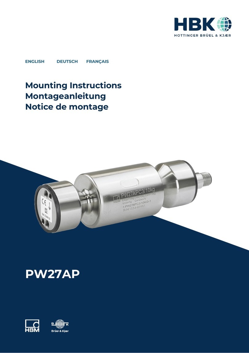
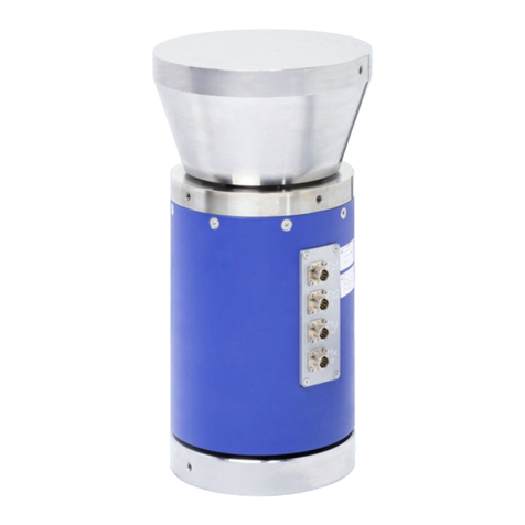
HBK Z30A User manual

TOP Transfer Z30A / Z4A
ENGLISH DEUTSCH
Mounting Instructions
Montageanleitung

Hottinger Brüel & Kjaer GmbH
Im Tiefen See 45
D-64293 Darmstadt
Tel. +49 6151 803-0
Fax +49 6151 803-9100
www.hbkworld.com
Mat.: 7-2001.0504
DVS: A02212 01 X00 01
05.2022
EHottinger Brüel & Kjaer GmbH
Subject to modifications.
All product descriptions are for general information
only. They are not to be understood as a guarantee of
quality or durability.
Änderungen vorbehalten.
Alle Angaben beschreiben unsere Produkte in allge
meiner Form. Sie stellen keine Beschaffenheits- oder
Haltbarkeitsgarantie dar.

TOP Transfer Z30A / Z4A
ENGLISH DEUTSCH
Mounting Instructions

TOP Transfer Z30A / Z4A
TABLE OF CONTENTS
2
TABLE OF CONTENTS
1 Safety instructions 3................................................
2 Markings used 5....................................................
2.1 The marking used in this document 5..................................
2.2 The marking on the product 5.........................................
3 Scope of supply 6...................................................
4 Application notes 8.................................................
5 Structure and mode of operation 9....................................
5.1 TOP-Z30A 9........................................................
5.2 TOP-Z4A 10.........................................................
6 Conditions on site 11.................................................
6.1 Ambient temperature 11..............................................
6.2 Moisture and dampness 11............................................
6.3 Air pressure 11......................................................
6.4 Chemical effects 11..................................................
6.5 Load disturbance variables 11.........................................
6.6 Electromagnetic compatibility 11.......................................
7 Mechanical installation 12............................................
7.1 Important precautions during installation 12..............................
7.2 Installation aids for compressive loading 12..............................
7.2.1 Installation diagram for compressive loading 13..........................
7.3 Installation aids for tensile loading 13...................................
8 Electrical connection 21..............................................
8.1 Notes on cabling 21..................................................
8.2 Pin Assignment 21...................................................
8.3 TEDS transducer identification 23......................................
9 Technical data per VDI 2638 and ISO 376 24.............................
9.1 TOP-Z30A 24........................................................
9.2 TOP-Z4A 26.........................................................
10 Dimensions TOP Transfer 28..........................................
10.1 TOP-Z30A and accessories 28.........................................
10.2 TOP-Z4A and accessories 33..........................................

3
TOP Transfer Z30A / Z4A
SAFETY INSTRUCTIONS
1 SAFETY INSTRUCTIONS
Intended use
The force transducers of TOP Transfer types: TOP-Z30A and TOP-Z4A must be used for
force comparison measurements (force transfer). Use for any additional purpose shall be
deemed to be not as intended.
In the interests of safety, the transducer should only be operated as described in the
Mounting Instructions. It is also essential to observe the appropriate legal and safety
regulations for the application concerned during use. The same applies to the use of ac
cessories.
The transducer is not a safety element within the meaning of its use as intended. For safe
and trouble‐free operation, this transducer must not only be correctly transported, stored,
sited and installed but must also be carefully operated and maintained.
General dangers of failing to follow the safety instructions
The force transducers TOP-Z30A and TOP-Z4A are state‐of‐the‐art and failsafe. Trans
ducers can give rise to remaining dangers if they are inappropriately installed and oper
ated by untrained personnel.
Everyone involved with the installation, commissioning, maintenance or repair of a force
transducer must have read and understood the Mounting Instructions and in particular
the technical safety instructions.
Remaining dangers
The scope of supply and performance of the transducer covers only a small area of force
measurement technology. In addition, equipment planners, installers and operators
should plan, implement and respond to the safety engineering considerations of force
measurement technology in such a way as to minimize remaining dangers. Prevailing
regulations must be complied with at all times. There must be reference to the remaining
dangers associated with force measurement technology.
Unauthorized conversions and modifications are prohibited
The transducer must not be modified from the design or safety engineering point of view
except with our express agreement. Any modification shall exclude all liability on our part
for any damage resulting therefrom.
Qualified personnel
These transducers must only be installed by qualified personnel, strictly in accordance
with the specifications in conjunction with the safety requirements and regulations listed
below. It is also essential to observe the appropriate legal and safety regulations for the
application concerned. The same applies to the use of accessories.

TOP Transfer Z30A / Z4A
SAFETY INSTRUCTIONS
4
Qualified personnel means persons entrusted with the installation, assembly, commis
sioning and operation of the product, who possess the appropriate qualifications for their
function.
Conditions at the place of installation
Protect the transducer from moisture and dampness or weather such as rain, snow, etc.
Maintenance
The force transducers TOP-Z30A and TOP-Z4A are maintenance‐free.
Accident prevention
The prevailing accident prevention regulations must be taken into account, even though
the nominal force values in the destructive range are well in excess of the full scale value.

5
TOP Transfer Z30A / Z4A
MARKINGS USED
2 MARKINGS USED
2.1 The marking used in this document
Important instructions for your safety are specifically identified. It is essential to follow
these instructions in order to prevent accidents and damage to property.
Symbol Significance
WARNING This marking warns of a potentially dangerous situ
ation in which failure to comply with safety require
ments can result in death or serious physical injury.
CAUTION This marking warns of a potentially dangerous
situation in which failure to comply with safety
requirements can result in slight or moderate physical
injury.
Notice This marking draws your attention to a situation in
which failure to comply with safety requirements can
lead to damage to property.
Important
This marking draws your attention to important in
formation about the product or about handling the
product.
Tip
This marking indicates application tips or other
information that is useful to you.
Information
This marking draws your attention to information
about the product or about handling the product.
Emphasis
See …
Italics are used to emphasize and highlight text and
identify references to sections, diagrams, or external
documents and files.
uThis marking indicates an action in a procedure
2.2 The marking on the product
The CE mark enables the manufacturer to guarantee that the
product complies with the requirements of the relevant EU direc
tives (the Declaration of Conformity can be found at
https://www.hbm.com/HBMdoc
).

TOP Transfer Z30A / Z4A
SCOPE OF SUPPLY
6
3 SCOPE OF SUPPLY
SForce transducer TOP-Z30A, TOP-Z4A
SOperating instructions TOP Transfer
The TOP Transfer force transducers are only available in conjunction with a DKD
calibration (not included in scope of supply)
SDKD calibration certificate to ISO 376 Order No. K-CAL-FD...
Accessories for TOP-Z30A
SKnuckle eyes ZGW/ZGOW
for 100 N to 1000 N: Order No. 1-U1R/200kg/ZGW
for 2 kN to 10 kN: Order No. 1-U2A/1t/ZGUW
SThrust piece to ISO 376
for 100 N to 1000 N: Order No. 1-EDO3/1kN
for 2 kN to 10 kN: Order No. 1-EDO4/50kN
SLoad button
for 100 N to 1000 N: Order No. 1-U1R/200kg/ZL
for 2 kN to 10 kN: Order No. 3-9202.0140
SZKM tensile force introduction part to ISO 376
for 2 kN to 10 kN: Order No. 1-Z30/10kN/ZKM
STransportation box
for 4 TOP-Z30A force transducer and accessories
Order No. 1-Z30/Box
Accessories for TOP-Z4A
SZKM tensile force introduction part to ISO 376
for 20 kN: Order No. 1-Z4/20kN/ZKM
50 kN: Order No. 1-Z4/50kN/ZKM
100 kN: Order No. 1-Z4/100kN/ZKM
200 kN: Order No. 1-Z4/200kN/ZKM
500 kN: Order No. 1-Z4/500kN/ZKM

7
TOP Transfer Z30A / Z4A
SCOPE OF SUPPLY
SKnuckle eyes ZGUW/ZGOW
for 20 kN: Order No. 1-Z4/20kN/ZGOW
1-Z4/20kN/ZGUW
50 kN: Order No. 1-U2A/2t/ZGOW
1-U2A/2t/ZGUW
100 kN: Order No. 1-Z4/100kN/ZGOW
1-Z4/100kN/ZGUW
200 kN: Order No. 1-U2A/10t/ZGOW
1-U2A/10t/ZGUW
500 kN: Order No. 1-Z4/500kN/ZGOW
1-Z4/500kN/ZGUW
SThrust piece EDO4 to ISO 376
20kN Order No. 1-EDO4/20kN
50kN Order No. 1-EDO4/50kN
100kN Order No. 1-EDO4/100kN
200kN Order No. 1-EDO4/200kN
500kN Order No. 1-EDO4/500kN
Cables/plugs
Description Order no.
Connection cable Kab 139A-6, 6m,with female cable
connector and free ends
1-KAB139A-6
Connector MS3106PEMV mounted on cable D-MS/MONT
15-pole D plug mounted on cable D-15D/MONT
TEDS ready mounted in 15-pole D plug for Z4A D-TEDS/MONT_DB

TOP Transfer Z30A / Z4A
APPLICATION NOTES
8
4 APPLICATION NOTES
Force transducer TOP Transfer
High precision force transducers in the type series TOP-Z30A and TOP-Z4A measure
compressive and tensile forces.
Because they measure static and quasi-static forces with extremely high accuracy and
reproducibility, they must be handled very carefully. Particular care must be taken when
transporting and installing the devices. Dropping or knocking the transducers may cause
permanent damage. It is recommended, as the TOP Transfer force transducers are peak
precision transducers for transfer measurements, that the ambient temperature is main
tained constant in the range of the nominal temperature.
Force transducers TOP-Z30A and TOP-Z4A with DKD certificate
The transducers are by default calibrated in the pressure direction. They can also be DKD
calibrated in the tensile direction on request. However, the transducer should be loaded
and used in one force direction only for high precision measurements.
The technical data lists the permissible limits for mechanical, thermal and electrical
stress. It is essential that these are taken into account when planning the measuring
set‐up, during installation and ultimately during operation.
To achieve optimum measurement results, the transducer must be connected to a highly
accurate amplifier (e.g. DMP40 from HBK).

9
TOP Transfer Z30A / Z4A
STRUCTURE AND MODE OF OPERATION
5 STRUCTURE AND MODE OF OPERATION
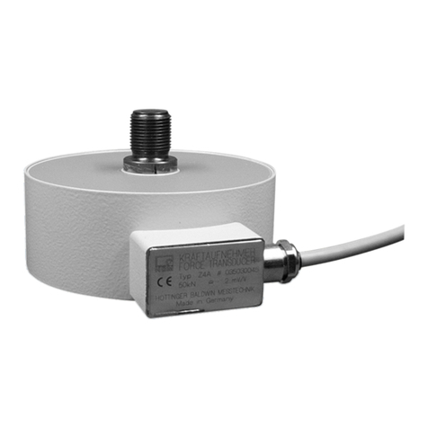
5.1 TOP-Z30A
Fig. 5.1 TOP-Z30A (100 N...10 kN)
The measuring body consists of a measurement spring system with strain gages. The
internal threads located on both sides are used to apply tensile forces. Load buttons to
screw into the upper thread are available as accessories to apply the compressive
forces.
All nominal forces of the TOP-Z30A have the same size.
The electric connection is implemented with Binder connectors.
To reduce the bending moment during tensile measurements, caused by the cable in lat
eral cable outputs, an additional connector is located on the floor of the housing.
Every TOP-Z30A force transducer comes with TEDS (Transducer electronic Data sheet);
see chapter 8.3.

TOP Transfer Z30A / Z4A
STRUCTURE AND MODE OF OPERATION
10
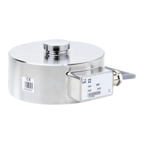
5.2 TOP-Z4A
Fig. 5.2 TOP-Z4A (20 kN...500 kN)
The measuring body consists of a measurement spring system with strain gages.
The TOP-Z4A transducer has a convex threaded pin on top (also suitable for application
of compressive forces) and a threaded bore underneath for the application of tensile
forces.
The housing is protected on top and bottom by thin metal membranes.

11
TOP Transfer Z30A / Z4A
CONDITIONS ON SITE
6 CONDITIONS ON SITE
6.1 Ambient temperature
The temperature effects on the zero signal and on the sensitivity are compensated. To
obtain optimum measurement results, the nominal (rated) temperature range must be
observed. Temperature-related measurement errors can be caused by heating on one
side (e.g. radiant heat) or by cooling. A radiation shield and all-round thermal insulation
produces noticeable improvements, but must not be allowed to set up a force shunt.
6.2 Moisture and dampness
Avoid extreme moisture or a tropical climate if the values are outside the classified limits
(TOP-Z4A degree of protection IP67 as per DIN EN 60529, TOP-Z30A: IP50).
6.3 Air pressure
Air pressure changes do not affect the TOP-Z30A force transducer.
Air pressure changes act on the TOP-Z4A force transducer as a change in force. With
normal ambient pressure changes ±20mbar, this influence on the measurement signal is
negligibly small (air pressure changes of ±10 mbar only have an effect on the zero signal
of 6 N with 20 kN‐ and 50 kN‐transducers).
6.4 Chemical effects
The transducer housings are protected by a powder coating. They must not be exposed
to adverse ambient conditions (direct weather conditions, contact with corrosive media).
The un-coated force application areas on the TOP-Z4A are greased to protect them
against corrosion.
6.5 Load disturbance variables
Torsion, bending and lateral loads are disturbance variables and therefore to be avoided.
Remedies can, if necessary, be implemented with HBK installation aids (Chapter 7.2 and
7.3).
6.6 Electromagnetic compatibility
The transducers are tested for use in controlled electromagnetic environments to EN
61326:2002;Tab B.1.

TOP Transfer Z30A / Z4A
MECHANICAL INSTALLATION
12
7 MECHANICAL INSTALLATION
7.1 Important precautions during installation
SHandle the transducers carefully, mechanical loads on the housing membranes must
be avoided
SAlways use thermally insulated gloves when handling the transducers
SEnsure there is enough time available before measurement to allow the force trans
ducer to reach a stable temperature with regards to its components and environment.
Approx. 24 hours are recommended for precision measurements.
SConnect the force transducer to the excitation voltage approx. 1 hour before measure
ment
SWhen measuring compressive forces, make sure the support structure is rigid and
level
SThe force application surfaces and threads must be perfectly clean and fully bearing
SObserve the depths of engagement for the threaded rods or knuckle eyes, different
depths will affect the reproducibility
SDo not overload the transducer, only load up to the operating force
SThe forces must act on the transducer as accurately as possible in the direction of
measurement.
WARNING
Additional safeguards must be provided if there is a risk that overloading the transducer
may cause it to break, which could put people at risk.
Notice
Torsional and bending moments, eccentric loading and lateral forces may produce mea
surement errors and destroy the transducer if limit values are exceeded.
7.2 Installation aids for compressive loading
Thrust pieces to ISO 376 are available for the application of compressive forces.
Thrust pieces EDO3/1kN or EDO4/50kN (see page 32) and two load buttons (see page 31)
are available for the TOP-Z30A. The thrust piece (see page 38) can be positioned directly
on the convex threaded pin in the TOP-Z4A.

13
TOP Transfer Z30A / Z4A
MECHANICAL INSTALLATION
7.2.1 Installation diagram for compressive loading
F
Transducer
TOP-Z30A TOP-Z4A
F
Thrust piece
Load button
Type Load button
Order number
Thrust piece
Order number
TOP-Z30A / 100 N - 1000 N 1-U1R/200kg/ZL 1-EDO3/1kN
TOP-Z30A / 2 kN - 10 kN 3-9202.0140 1-EDO4/50kN
TOP-Z4A / 20 kN - 1-EDO4/20kN
TOP-Z4A / 50 kN - 1-EDO4/50kN
TOP-Z4A / 100 kN - 1-EDO4/100kN
TOP-Z4A / 200 kN - 1-EDO4/200kN
TOP-Z4A / 500 kN - 1-EDO4/500kN
7.3 Installation aids for tensile loading
Knuckle eyes and tensile force introduction parts (ZKM) to ISO 376 are available to install
the TOP-Z30A and TOP-Z4A. These installation aids prevent the application of torsional
moments and, where 2 knuckle eyes are used, bending moments, together with lateral
and oblique loads in the transducer. They are intended only for static tensile loading of
the transducer.

TOP Transfer Z30A / Z4A
MECHANICAL INSTALLATION
14
Installation of knuckle eyes
uScrew the knuckle eye thread into the transducer thread until the stop is reach and
then screw it one and a half turns back out.
Knuckle eyes ZGOW/ZGUW for TOP-Z4A
W
a
f
Knuckle eyes ZGW/ZGUW for TOP-Z30A
∅B
a
f
Type Knuckle eye top/bottom
Order number a f W B
TOP-Z30A/100N - 1000N 1-U1R/200kg/ZGW 147.5 170 12 8H7
TOP-Z30A/2kN - 10kN 1-U2A/1t/ZGUW 169 201 16 12H7

15
TOP Transfer Z30A / Z4A
MECHANICAL INSTALLATION
Type
Knuckle eye top/
bottom
Order number
Weigh
t (kg)
a f
W∅B
min max. min max.
TOP‐Z4A/
20kN
1-Z4/20kN/ZGOW
1-Z4/20kN/ZGUW 0.2 appr.
158
appr.
170
appr.
198
appr.
210 21 16H7
TOP‐Z4A/
50kN
1-U2A/2t/ZGOW
1-U2A/2t/ZGUW
0.8
0.4
appr.
190
appr.
199
appr.
245
appr.
254 25 20H7
TOP‐Z4A/
100kN
1-Z4/100kN/ZGOW
1-Z4/100kN/ZGUW 1.1 appr.
261
appr.
269
appr.
331
appr.
339 37 30H7
TOP‐Z4A/
200kN
1-U2A/10t/ ZGOW
1-U2A/10t/ZGUW
3.2
1.1
appr.
352
appr.
357
appr.
475
appr.
480 35 50 +0.001
-0.014
TOP‐Z4A/
500kN
1-Z4/500kN/ZGOW
1-Z4/500kN/ZGUW
1.,3
12.0
appr.
570
appr.
590
appr.
764
appr.
784 44 60 +0.003
-0.018
Information
With the TOP-Z30A, the nut on the base must be tightened before the upper nut; to do this,
hold the TOP-Z30A firmly with the spanner flats.
Notes on mounting with knuckle eyes
1. Shaft diameter
When using a sensor with knuckle eyes mounted on one or both sides, make sure that the
shaft is the right size.
You will find the diameters of the knuckle eyes and shafts and their recommended
tolerances in the table below.
Knuckle eyes TOP-Z30A
Knuckle eyes Nominal
diameter
Hole fitting
size
Recommended shaft
fitting size
1-U1R/200kg/ZGW 8 H7 g6
1-U2a/1t/ZGUW 12
Tab. 7.1 Recommended fitting sizes/tolerances for shaft and hole - Z30A

TOP Transfer Z30A / Z4A
MECHANICAL INSTALLATION
16
Knuckle eyes TOP-Z4A / Knuckle eyes with internal thread
Knuckle eyes Nominal
diameter
Hole fitting
size
Recommended shaft
fitting size
1-Z4/20kN/ZGOW 16
H7 g6
1-U2A/2T/ZGOW 20
1-U2A/100kN/ZGOW 30
1-U2A/10T/ZGOW 50 +0.002
-0.014 f6
1-Z4/500kN/ZGOW 60 +0.003
-0.018
Tab. 7.2 Recommended fitting sizes/tolerances for shaft and hole - Knuckle eyes with
internal thread
Knuckle eyes TOP-Z4A / Knuckle eyes with external thread
Knuckle eyes Nominal
diameter
Hole fitting
size
Recommended shaft
fitting size
1-Z4/20kN/ZGUW 16
H7 g6
1-U2A/2T/ZGUW 20
1-U2A/100kN/ZGUW 30
1-U2A/10T/ZGUW 50 +0,002
-0,014 f6
1-Z4/500kN/ZGUW 60 +0,003
-0,018
Tab. 7.3 Recommended fitting sizes/tolerances for shaft and hole - Knuckle eyes with
external thread

17
TOP Transfer Z30A / Z4A
MECHANICAL INSTALLATION
Customer's construction
Customer's shaft holder
Shaft
Play based on recommended fitting
size, see Tab. 7.1, Tab. 7.2 and
Tab. 7.3, page 15
Threaded connector for mounting
on force transducers
Fig. 7.1 Example diagram of installation with knuckle eye
CAUTION
If a shaft with an overly small diameter is used, the bearing of the knuckle eye will be
subjected to linear load. This subjects the inner bearing shell to excessive load, which can
lead to damage and, if forces are high, can cause the knuckle eye bearing to break.
Select the shaft as recommended in the mounting instructions.
2. Distance between knuckle eye and shaft bearing
The shaft support must allow for suitable play between the knuckle eye and the shaft
bearing.

TOP Transfer Z30A / Z4A
MECHANICAL INSTALLATION
18
CAUTION
If there is too much distance between the knuckle eye and the shaft bearing, this generates
bending moments in the shaft, causing it to deform.
This deformation puts strain on points of the edges of the inner bearing shell, which can
cause the knuckle eye or shaft to suffer damage or break.
Select the play as recommended in the mounting instructions.
To determine the play between the knuckle eye and the shaft bearing, you can apply the
following rule of thumb:
Shaft diameter Play between knuckle eye and bearing
≤30mm 1/10 of the nominal diameter
>30mm 1/20 of the nominal diameter
Tab. 7.4 Rule of thumb for determining play between knuckle eye and shaft bearing
Based on this, recommendations for the play between the knuckle eye and shaft bearing
are as follows:
TOP-Z30A
Knuckle eye Play between knuckle eye and shaft bearing
1-U1R/200kg/ZGW 0.8 mm
1-U2a/1t/ZGUW 1.2 mm
Tab. 7.5 Recommendations for play between knuckle eye and shaft bearing - Z30A
TOP-Z4A
Knuckle eye Play between knuckle eye and shaft bearing
1-Z4/20kN/ZOGW 1.6 mm
1-Z4/20kN/ZUGW
1-U2A/2T/ZGOW 2 mm
1-U2A/2T/ZGUW
1-Z4/100kN/ZOGW 3 mm
1-Z4/100kN/ZUGW
1-U2A/10T/ZGOW 2.5 mm
1-U2A/10T/ZGUW
Other manuals for Z30A
1
This manual suits for next models
3
Table of contents
Languages:
Other HBK Measuring Instrument manuals

