HBK PWSE User manual

PWSE
ENGLISH DEUTSCH FRANÇAIS
Mounting Instructions
Montageanleitung
Notice de montage

Hottinger Brüel & Kjaer GmbH
Im Tiefen See 45
D-64293 Darmstadt
Tel. +49 6151 803-0
Fax +49 6151 803-9100
www.hbkworld.com
Mat.: 7-2002.3361
DVS: A03361 01 Y00 01
06.2023
EHottinger Brüel & Kjaer GmbH
Subject to modifications.
All product descriptions are for general information
only. They are not to be understood as a guarantee of
quality or durability.
Änderungen vorbehalten.
Alle Angaben beschreiben unsere Produkte in allge
meiner Form. Sie stellen keine Beschaffenheits- oder
Haltbarkeitsgarantie dar.
Sous réserve de modifications.
Les caractéristiques indiquées ne décrivent nos
produits que sous une forme générale. Elles
n'impliquent aucune garantie de qualité ou de
durabilité.

PWSE
ENGLISH DEUTSCH FRANÇAIS
Mounting Instructions

PWSE
TABLE OF CONTENTS
2
TABLE OF CONTENTS
1 Safety instructions 3................................................
2 Markings used 6....................................................
2.1 The markings used in this document 6.................................
2.2 The marking used on the product 6....................................
3 Conditions on site 7.................................................
3.1 Protection against corrosion 7........................................
3.2 Deposits 7.........................................................
4 Mechanical installation 8............................................
4.1 Important precautions during installation 8..............................
4.2 Mounting 8........................................................
5 Electrical connection 10..............................................
5.1 Connection with six‐wire configuration 10................................
5.2 Connection with four‐wire configuration 10...............................
5.3 Shortening the cable 11...............................................
5.4 Cable extension 11...................................................
5.5 EMC protection 11...................................................
6 Specifications 12....................................................
7 Dimensions 14......................................................

3
PWSE
1 SAFETY INSTRUCTIONS
Proper use
Load cells of the PWSE type series are designed for technical weighing applications
within the load limits detailed in the specifications. Any other use is not the designated
use.
The load cells may only be installed by qualified personnel in compliance with the spe
cifications and with the safety requirements and regulations of these mounting instruc
tions. It is also essential to observe the applicable legal and safety regulations for the
application concerned. The same applies to the use of accessories.
Load cells are not intended for use as safety components. Please also refer to the sec
tion: “Additional safety precautions". Proper and safe operation of the load cells requires
proper transportation, correct storage, siting and mounting, and careful operation.
Loading capacity limits
The data in the technical data sheet must be complied with when using the load cells. In
particular, the respective maximum loads specified must never be exceeded. The follow
ing limits set out in the specifications must not be exceeded, e.g.:
SLimit load
SLimit load at max. eccentricity
SLimit lateral loading
SBreaking loads
STemperature limits
SLimits of electrical loading capacity
Note that, when several load cells are installed in a scale, there is not always an even dis
tribution of load on the individual load cells.
Use as a machine element
The load cells can be used as machine elements. When used in this manner, it must be
noted that, to favor greater sensitivity, the load cell is not designed with the safety factors
usual in mechanical engineering. Please refer here to the section “Loading capacity lim
its" and to the specifications.
Accident prevention
The prevailing accident prevention regulations must be taken into account, even though
the maximum capacity values in the destructive range are well in excess of the full scale
value.

PWSE
4
Additional safety precautions
Load cells cannot (as passive transducers) implement any (safety‐relevant) cutoffs. This
requires additional components and constructive measures for which the installer and
operator of the plant is responsible.
In cases where a breakage or malfunction of the load cells would cause injury to persons
or damage to equipment, the user must take appropriate additional safety measures that
meet at least the requirements of applicable safety and accident prevention regulations
(e.g. automatic emergency shutdown, overload protection, catch straps or chains, or
other fall protection).
The layout of the electronics conditioning the measurement signal should be such that
measurement signal failure does not cause damage.
General dangers of failing to follow the safety instructions
Load cells are state‐of‐the‐art and reliable. Transducers can give rise to residual dangers
if they are incorrectly operated or inappropriately mounted, installed and operated by
untrained personnel. Everyone involved with siting, starting up, operating or repairing a
load cell must have read and understood the Mounting Instructions and in particular the
technical safety instructions. The load cells can be damaged or destroyed by non‐desig
nated use of the load cells or by non‐compliance with the mounting and operating instruc
tions, these safety instructions or any other applicable safety regulations (BG safety and
accident prevention regulations) when using the load cells. Load cells can break, particu
larly in the case of overloading. The breakage of a load cell can also cause damage to
property or injury to persons in the vicinity of the load cell.
If load cells are not used according to their designated use, or if the safety instructions or
specifications in the mounting and operating instructions are ignored, it is also possible
that the load cells may fail or malfunction, with the result that persons or property may be
affected (due to the loads acting on or being monitored by the load cells).
The scope of supply and performance of the transducer covers only a small area of
weighing technology, as measurements with (resistive) strain gauge sensors presuppose
the use of electronic signal processing. In addition, equipment planners, installers and
operators should plan, implement and respond to the safety engineering considerations
of the weighing technology in such a way as to minimize residual dangers. Pertinent
national and local regulations must be complied with.
Conversions and modifications
The transducer must not be modified from the design or safety engineering point of view
except with our express agreement. Any modification shall exclude all liability on our part
for any damage resulting therefrom.
Maintenance
The PWSE load cells are maintenance free.

5
PWSE
Selling on
If the load cell is sold on, these mounting instructions must be included with the load cell.
Environmental protection, disposal
In accordance with national and local environmental protection and material recovery and
recycling regulations, old transducers that can no longer be used must be disposed of
separately and not with normal household waste.
If you need more information about waste disposal, please contact your local authorities
or the dealer from whom you purchased the product.
Qualified personnel
Qualified personnel means persons entrusted with siting, mounting, starting up and oper
ating the product, who possess the appropriate qualifications for their function.
This includes people who meet at least one of the three following requirements:
SKnowledge of the safety concepts of automation technology is a requirement and as
project personnel, you must be familiar with these concepts.
SAs automation plant operating personnel, you have been instructed how to handle the
machinery. You are familiar with the operation of the equipment and technologies
described in this documentation.
SAs commissioning engineers or service engineers, you have successfully completed
the training to qualify you to repair the automation systems. You are also authorized
to activate, ground and label circuits and equipment in accordance with safety engin
eering standards.
PWSE
MARKINGS USED
6
2 MARKINGS USED
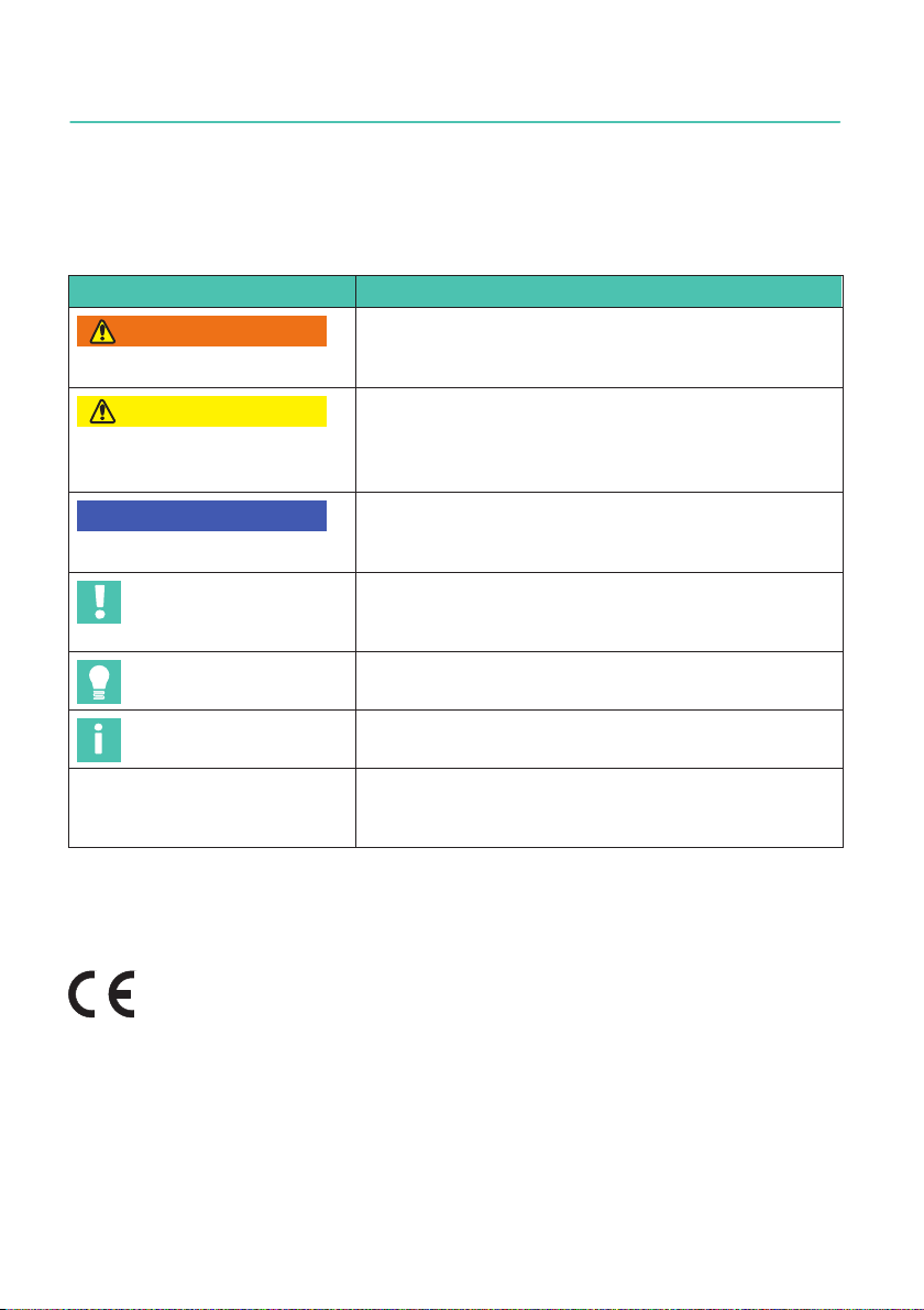
2.1 The markings used in this document
Important instructions for your safety are specifically identified. It is essential to follow
these instructions in order to prevent accidents and damage to property.
Symbol Significance
WARNING This marking warns of a potentially dangerous situ
ation in which failure to comply with safety require
ments can result in death or serious physical injury.
CAUTION This marking warns of a potentially dangerous
situation in which failure to comply with safety
requirements can result in slight or moderate physical
injury.
Notice This marking draws your attention to a situation in
which failure to comply with safety requirements can
lead to damage to property.
Important
This marking draws your attention to important in
formation about the product or about handling the
product.
Tip
This marking indicates application tips or other
information that is useful to you.
Information
This marking draws your attention to information
about the product or about handling the product.
Emphasis
See …
Italics are used to emphasize and highlight text and
identify references to sections, diagrams, or external
documents and files.
2.2 The marking used on the product
CE mark
The CE mark enables the manufacturer to guarantee that the product com
plies with the requirements of the relevant EC directives (the declaration of
conformity is available at http://www.hbm.com/HBMdoc).

7
PWSE
CONDITIONS ON SITE
3 CONDITIONS ON SITE
The PWSE series load cells reach the protection class IP67.
3.1 Protection against corrosion
The load cells must be protected against chemicals that could attack the transducer body
(stainless) steel or the cable.
Notice
Acids and all substances that release ions also attack stainless steels and their welded
seams.
Should there be any corrosion, this could cause the transducer to fail. In this case, appro
priate protective measures should be implemented.
3.2 Deposits
Dust, dirt and other foreign matter must not be allowed to accumulate sufficiently to
divert some of the measuring force onto the housing, thus invalidating the measured
value (force shunt).
PWSE
MECHANICAL INSTALLATION
8
4 MECHANICAL INSTALLATION
4.1 Important precautions during installation
SHandle the transducer with care.
SWelding currents must not be allowed to flow over the transducer. If there is a risk
that this might happen, you must use a suitable low‐ohm connection to electrically
bypass the transducer. HBM, for example, provides the highly flexible EEK ground
cable, which can be screwed on above and below the transducer.
SMake sure that the transducer cannot be overloaded.
WARNING
There is a danger of the transducer breaking if it is overloaded. This can cause danger for
the operating personnel of the system in which the transducer is installed.
Implement appropriate safety measures to avoid overloads or to protect against resulting
dangers.
Notice
Load cells are precision measuring elements and need to be handled carefully. Dropping or
knocking the transducer may cause permanent damage. Make sure that the transducer
cannot be overloaded, even while it is being mounted.
4.2 Mounting
Attach the load cells at the mounting holes and apply the load to the other end. The
screws and tightening torques to be used are given in the following table:
Maximum capacity Thread Min. property class Tightening torque1)
100 …300kg M10 10.9 66N⋅m
500 …750kg M12 10.9 115N⋅m
1) Recommendedvalue for the specified property class. Please comply with the screw manufacturer's
instructions with regard to screw dimensions.

9
PWSE
MECHANICAL INSTALLATION
= =
= =
Platformcenter
Load
application
Connection cable
Mounting
Spacing disc
Fig. 4.1 Load application and installation
Important
Load must not be applied to the side where the cable connection is located, as this would
cause a force shunt.

PWSE
ELECTRICAL CONNECTION
10
5 ELECTRICAL CONNECTION
The following can be connected for measurement signal conditioning:
SCarrier‐frequency amplifier
SDC amplifier
designed for strain gauge measurement systems.
The transducers are supplied in the standard version with a 3m cable and 6‐pin Pancon
connector in a six‐wire configuration.
5.1 Connection with six‐wire configuration
Schematic diagram of a Pancon connector (CE100F26‐6), 6‐pin
blue marking
412356
Plug‐in contact 1 (white) = measurement signal (+)
Plug‐in contact 3 (black) = excitation voltage (-)
Plug‐in contact 6 (gray) = sense lead (-)
Plug‐in contact 4 (blue) = excitation voltage (+)
Plug‐in contact 5 (green) = sense lead (+)
Plug‐in contact 2 (red) = measurement signal (-)
Shield (yellow) = cable shield connected to
load cell body
Fig. 5.1 Connection with a 6‐wire cable (choice of lengths: 3m, 6m or 12m)
With this cable assignment, the output voltage at the measuring amplifier is positive
when the transducer is loaded (see Fig. 4.1).
5.2 Connection with four‐wire configuration
When transducers with a six‐wire configuration are connected to amplifiers with a
four‐wire configuration, the sense leads of the transducer must be connected to the cor
responding supply leads: Identification (+) with (+) and identification (-) with (-), see
Fig. 5.1. This measure also reduces the cable resistance of the excitation voltage leads.
Important
However, there will be a voltage loss on the supply leads due to the cable resistance that is
still present and not compensated for by the six‐wire configuration, even after connecting
the sense leads to the excitation voltage circuit. A large part of this loss can be eliminated
by a calibration, however, the temperature‐dependent part remains.
The TKcvalue given in the specifications for the transducer therefore does not apply for
the cable and transducer combination when connection is with four‐wire configuration, the
cable percentage must be added.

11
PWSE
ELECTRICAL CONNECTION
5.3 Shortening the cable
If the transducer is connected to an amplifier with a six‐wire configuration, the transducer
cable can be shortened as required, without adversely affecting the measurement accur
acy.
5.4 Cable extension
Only use shielded, low‐capacitance measurement cables for extension. Ensure that con
nection is perfect, with a low contact resistance.
The cable of a six‐wire transducer can be extended with a cable of the same type.
5.5 EMC protection
Electrical and magnetic fields often induce interference voltages in the measuring circuit.
To ensure reliable measurement, however, the transducer must be able to transmit signal
differences of a few μV to the analysis unit without interference.
Planning the shielding design
Due to the numerous application options and differing local constraints, we can only
provide you with general information on correct connection. The shielding design suitable
for your application must be planned locally by an appropriate specialist.
HBM load cells with shielded, round cables are EMC-tested in accordance with the
EU Directive and bear the CE mark. Voltage surges as per EN 61000-4-5 can give rise to
deviations from the load cell’s specified accuracy. These surges in plants are caused by
lightning strikes or switching operations in power circuits, for example, and disappear
again when interference is no longer active. This is particularly evident with cables over
30 m long or if the equipment is used outdoors. Customers should take additional pre
cautions in these cases.
Please note:
SConnect the connecting cable shield all over the surface of the shielding electronics
housing. When using several load cells, connect the shields all over the surface of the
junction box (combination of transducer signals, e.g. type VKK2 from HBM). From
there, connect the measurement cable for the electronics over the surface of the
junction box and the shielding electronics housing.
SThe shield of the connecting cable must not be used for discharging potential
differences within the system. You must therefore lay sufficiently dimensioned
potential equalization lines to compensate for possible potential differences.
SUse shielded low-capacitance measurement cables only (HBM cables fulfill these
conditions).
SDo not route measurement cables parallel to electric cables, especially power lines
and control circuits. If this is not possible, protect the measurement cable, for
example with steel conduits.
SAvoid stray fields from transformers, motors and contact switches.

PWSE
SPECIFICATIONS
12
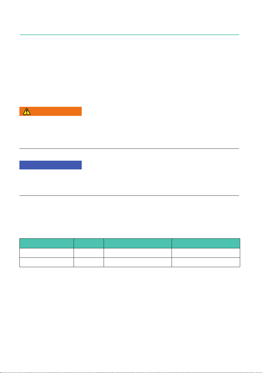
6 SPECIFICATIONS
Type PWSE
Accuracy class 1) C3MR
Number of scale intervals nLC 3000
Maximum capacity 1) (Emax)Emax kg 100 200 300 500 750
Minimum scale division (vmin)vmin g 10 20 50 50 100
Temperature coefficient of zero
signal per 10K 3) TK0
% of
Cn
±0.0140
±0.0140
±0.0093
±0.0140
±0.0093
Nominal platform dimensions mm 600 x 800
Maximum platform size mm 800 x 800
Nominal (rated) sensitivity (Cn)CnmV/V 2.0 ±0.2
Zero signal error ±0.1
Temperature coefficient of the
sensitivity per 10K 2) 3) in the
temperature range
+20 ... +40 °C
-10 ... +20 °C
TKC
% of
Cn
±0.0170
±0.0117
Relative reversibility error 2) 3) dhy ±0.0166
Linearity deviation 2) 3) dlin ±0.0166
Relative creep over 30min dcr ±0.0166
Off‐center load error 3) ±0.0166
Input resistance RLC Ω390 ±15
Output resistance R0359 ±10
Reference excitation voltage Uref
V
5
Nominal (rated) range of the
excitation voltage BU0 ... 12
Maximum excitation voltage 15
Insulation resistance at 100 VDC Ris GΩ > 2
Nominal (rated) temperature
range BT
°C
-10 ... +40
Operating temperature range Btu -10 ... +50
Storage temperature range Btl -25 ... +70
13
PWSE
SPECIFICATIONS
PWSEType
C3MRAccuracy class 1)
750500300200100kgEmax
Maximum capacity 1) (Emax)
Limit load at maximum 100mm
eccentricity EL% of
Emax
150
Limit lateral loading, static Elq 300
Breaking load Ed300
Nominal displacement 4) snom mm < 0.5
Weight, approx. Gkg 0.9 0.9 1.1 1.2 1.2
Degree of protection per DIN EN 60529
(IEC 529)
IP67
Cable length (standard) m 3
Material
Measuring body
Cable sheath
Stainless steel 1.4545
PVC
1) As per OIML R60, with PLC = 0.7.
2) The values for non‐linearity (dlin), relative reversibility error (dhy) and temperature coefficient of
sensitivity (TKC) are recommended values. The sum of these values is within the cumulative error limits
laid down by OIML R60.
3) As per OIML R76.
4) Loading with Emax and center of gravity in center of load cell.

PWSE
DIMENSIONS
14
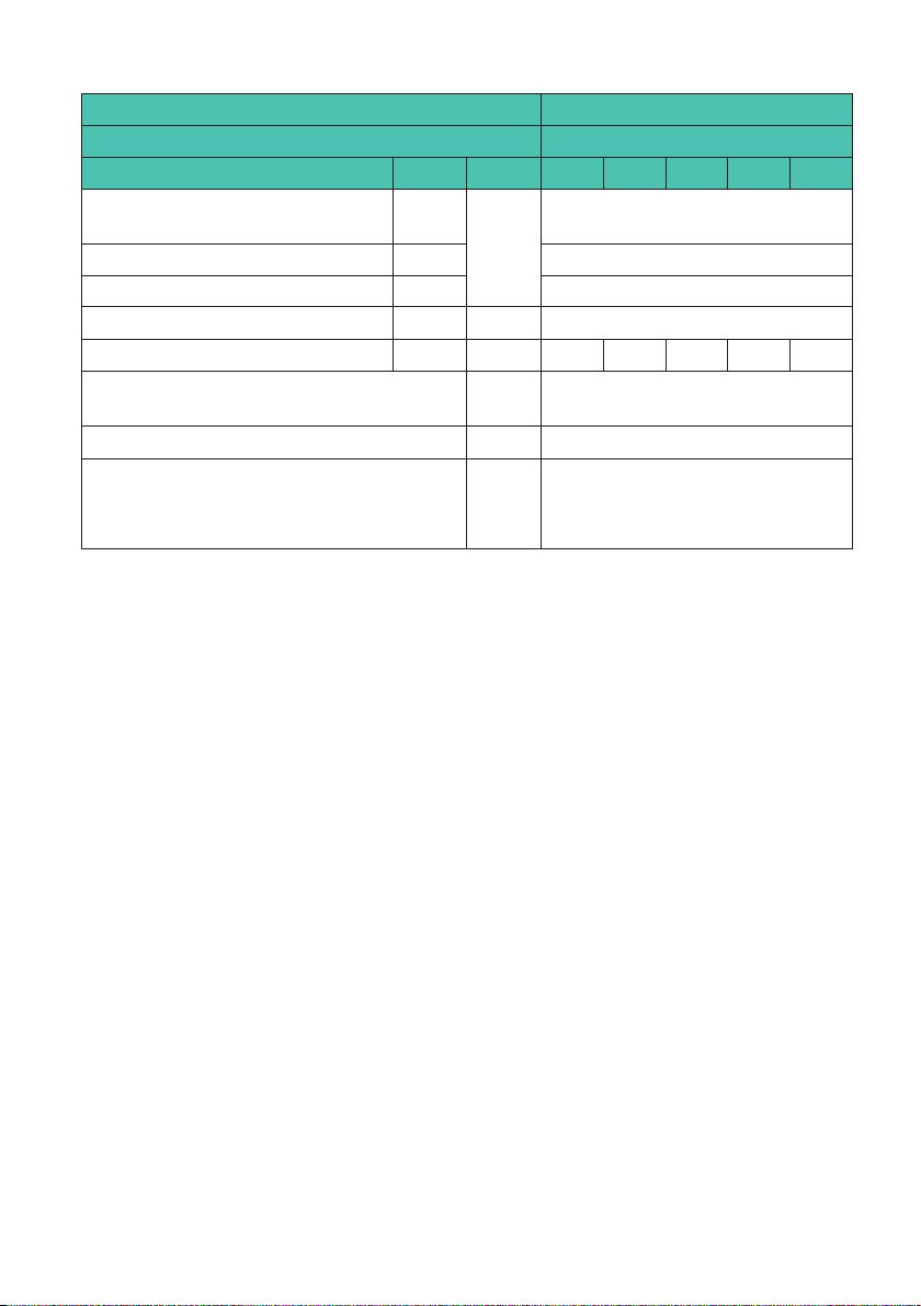
7 DIMENSIONS
Dimensions in mm (1 mm = 0.03937 inch)
H
38.1
G
T
W
7.8 22.4±0.1 79.3±0.1 22.4±0.1
139.7
Load direction / platform center
Maximum capacity H W G T
100 …200kg 30.2 30.5 M10 15
300kg 36.5 36.5 M10 19
500 …750kg 36.5 36.5 M12 19

PWSE
ENGLISH DEUTSCH FRANÇAIS
Montageanleitung

PWSE
INHALTSVERZEICHNIS
2
INHALTSVERZEICHNIS
1 Sicherheitshinweise 3...............................................
2 Verwendete Kennzeichnungen 6......................................
2.1 In dieser Anleitung verwendete Kennzeichnungen 6......................
2.2 Auf dem Gerät angebrachte Symbole 6.................................
3 Bedingungen am Einbauort 7.........................................
3.1 Korrosionsschutz 7.................................................
3.2 Ablagerungen 7.....................................................
4 Mechanischer Einbau 8..............................................
4.1 Wichtige Vorkehrungen beim Einbau 8.................................
4.2 Montage 8.........................................................
5 Elektrischer Anschluss 10............................................
5.1 Anschluss in Sechsleiter‐Technik 10....................................
5.2 Anschluss in Vierleiter‐Technik 10......................................
5.3 Kabelkürzung 11.....................................................
5.4 Kabelverlängerung 11................................................
5.5 EMV-Schutz 11......................................................
6 Technische Daten 13.................................................
7 Abmessungen 15....................................................

3
PWSE
SICHERHEITSHINWEISE
1 SICHERHEITSHINWEISE
Bestimmungsgemäße Verwendung
Die Wägezellen der Typenreihe PWSE sind für wägetechnische Anwendungen im
Rahmen der durch die technischen Daten spezifizierten Belastungsgrenzen konzipiert.
Jeder andere Gebrauch ist nicht bestimmungsgemäß.
Die Wägezellen dürfen nur von qualifiziertem Personal ausschließlich entsprechend der
technischen Daten unter Beachtung der Sicherheitsbestimmungen und Vorschriften
dieser Montageanleitung eingesetzt werden. Zusätzlich sind die für den jeweiligen
Anwendungsfall geltenden Rechts‐ und Sicherheitsvorschriften zu beachten. Sinngemäß
gilt dies auch bei Verwendung von Zubehör.
Die Wägezellen sind nicht zum Einsatz als Sicherheitsbauteile bestimmt. Bitte beachten
Sie hierzu den Abschnitt „Zusätzliche Sicherheitsvorkehrungen“. Der einwandfreie und
sichere Betrieb der Wägezellen setzt sachgemäßen Transport, fachgerechte Lagerung,
Aufstellung und Montage sowie sorgfältige Bedienung voraus.
Belastbarkeitsgrenzen
Beim Einsatz der Wägezellen sind die Angaben in den technischen Datenblättern unbe
dingt zu beachten. Insbesondere dürfen die jeweils angegebenen Maximalbelastungen
keinesfalls überschritten werden. Nicht überschritten werden dürfen z.B. die in den
technischen Datenblättern angegebenen Werte für
SGrenzlast
SGrenzlast bei max. Exzentrizität
SGrenzquerbelastung
SBruchlasten
STemperaturgrenzen
SGrenzen der elektrischen Belastbarkeit
Beachten Sie, dass beim Einbau mehrerer Wägezellen in eine Waage die Lastverteilung
auf die einzelnen Wägezellen nicht immer gleichmäßig ist.
Einsatz als Maschinenelemente
Die Wägezellen können als Maschinenelemente eingesetzt werden. Bei dieser
Verwendung ist zu beachten, dass die Wägezellen zu Gunsten einer hohen Messempfind
lichkeit nicht mit den im Maschinenbau üblichen Sicherheitsfaktoren konstruiert wurden.
Beachten Sie hierzu den Abschnitt „Belastbarkeitsgrenzen“ und die technischen Daten.

PWSE
SICHERHEITSHINWEISE
4
Unfallverhütung
Obwohl die angegebene Nennlast im Zerstörungsbereich ein Mehrfaches vom Messbe
reichsendwert beträgt, müssen die einschlägigen Unfallverhütungsvorschriften der
Berufsgenossenschaften berücksichtigt werden.
Zusätzliche Sicherheitsvorkehrungen
Die Wägezellen können (als passive Aufnehmer) keine (sicherheitsrelevanten)
Abschaltungen vornehmen. Dafür bedarf es weiterer Komponenten und konstruktiver
Vorkehrungen, für die der Errichter und Betreiber der Anlage Sorge zu tragen hat.
Wo bei Bruch oder Fehlfunktion der Wägezellen Menschen oder Sachen zu Schaden
kommen können, müssen vom Anwender geeignete zusätzliche Sicherheitsvorkehrungen
getroffen werden, die zumindest den Anforderungen der einschlägigen Unfallverhütungs
vorschriften genügen (z.B. automatische Notabschaltungen, Überlastsicherungen,
Fanglaschen oder ‐ketten oder andere Absturzsicherungen).
Die das Messsignal verarbeitende Elektronik ist so zu gestalten, dass bei Ausfall des
Messsignals keine Folgeschäden auftreten können.
Allgemeine Gefahren bei Nichtbeachten der Sicherheitshinweise
Die Wägezellen entsprechen dem Stand der Technik und sind betriebssicher. Von den
Aufnehmern können Gefahren ausgehen, wenn sie von ungeschultem Personal oder
unsachgemäß montiert, aufgestellt, eingesetzt und bedient werden. Jede Person, die mit
Aufstellung, Inbetriebnahme, Betrieb oder Reparatur einer Wägezelle beauftragt ist, muss
die Montageanleitung und insbesondere die sicherheitstechnischen Hinweise gelesen
und verstanden haben. Bei nicht bestimmungsgemäßem Gebrauch der Wägezellen, bei
Nichtbeachtung der Montage‐ und Bedienungsanleitung, dieser Sicherheitshinweise oder
sonstiger einschlägiger Sicherheitsvorschriften (Unfallverhütungsvorschriften der BG)
beim Umgang mit den Wägezellen, können die Wägezellen beschädigt oder zerstört
werden. Insbesondere bei Überlastungen kann es zum Bruch von Wägezellen kommen.
Durch den Bruch einer Wägezelle können darüber hinaus Sachen oder Personen in der
Umgebung der Wägezelle zu Schaden kommen.
Werden Wägezellen nicht ihrer Bestimmung gemäß eingesetzt oder werden die
Sicherheitshinweise oder die Vorgaben der Montage‐ oder Bedienungsanleitung außer
Acht gelassen, kann es ferner zum Ausfall oder zu Fehlfunktionen der Wägezellen kom
men, mit der Folge, dass (durch auf die Wägezellen einwirkende oder durch diese
überwachte Lasten) Menschen oder Sachen zu Schaden kommen können.
Der Leistungs‐ und Lieferumfang des Aufnehmers deckt nur einen Teilbereich der Wäge
technik ab, da Messungen mit (resistiven) DMS‐Sensoren eine elektronische Signalver
arbeitung voraussetzen. Sicherheitstechnische Belange der Wägetechnik sind zusätzlich
vom Anlagenplaner/Ausrüster/Betreiber so zu planen, zu realisieren und zu verantworten,
dass Restgefahren minimiert werden. Die jeweils existierenden nationalen und örtlichen
Vorschriften sind zu beachten.
Table of contents
Languages:
Other HBK Measuring Instrument manuals


